| “This site contains affiliate links for which OEMDTC may be compensated” |
NHTSA Campaign Number: 16V202
Component(s): ELECTRICAL SYSTEM , POWER TRAIN
Potential Number of Units Affected: 26,867
Manufacturer: Chrysler (FCA US LLC)
SUMMARY:
Chrysler (FCA US LLC) is recalling certain model year 2015-2016 Ram
 ProMaster City vans manufactured September 26, 2014, to March 5, 2016.
A low-voltage electrical harness connector by the front driver seat may be susceptible to water intrusion and corrosion.
Corrosion may result in a loss of communication to the Transmission Control Module (TCM) and may cause the transmission to unexpectedly shift into and stay in neutral without warning the next time that the vehicle stops.
CONSEQUENCE:
An unintended shift into neutral will prevent the vehicle from being moved.
Additionally, if the driver turns off the engine, the driver will be unable to restart the engine.
Both scenarios can increase the risk of a crash.
REMEDY:
Chrysler will notify owners, and dealers will relocate the harness connector to under the instrument panel, free of charge.
The recall began on June 3, 2016.
Owners may contact Chrysler customer service at 1-800-853-1403.
Chrysler ’s number for this recall is S24.
NOTES:
Owners may also contact the National Highway Traffic Safety Administration Vehicle Safety Hotline at 1-888-327-4236 (TTY 1-800-424-9153), or go to www.safercar.gov.
Check if your Vehicle has a Recall
Revised August 2016
Dealer Service Instructions for:
Safety Recall S24 / NHTSA 16V-202 CAN-C Bus Connector
NOTE: Revised Step 4 and Figure 2 in Section A. Inspect CAN – C Bus Connector.
Models
| 2015-2016 | (VM) | RAM ProMaster City ProMaster City |
NOTE: This recall applies only to the above vehicles built through March 05, 2016 (MDH 030500).
| IMPORTANT: Some of the involved vehicles may be in dealer new vehicle inventory. Federal law requires you to complete this recall service on these vehicles before retail delivery. Dealers should also consider this requirement to apply to used vehicle inventory and should perform this recall on vehicles in for service. Involved vehicles can be determined by using the VIP inquiry process. |
Subject
The CAN-C bus communication connector on about 23,900 of the above vehicles may develop internal connector pin corrosion due to moisture.
Corroded CAN-C bus communication connector pin(s) could lead to a loss of electrical contact and/or a loss of communication to the Transmission Control Module (TCM). A loss of communication to the TCM could cause the transmission to perform an unrequested shift into neutral. The vehicle operator would be unable to reengage the transmission. This could cause a crash without warning.
Repair
The CAN-C bus communication connector must be inspected for pin corrosion. Vehicles found with corroded CAN-C bus connector pin(s) must have the connector replaced.
All involved vehicles must also have the CAN-C bus communication connector relocated to a new location under the instrument panel.
Parts Information
| Part Number | Description |
|---|---|
| 68084588AA | Connector, CAN C-Bus |
| 68137880AA | Connector Kit, Three Way (1 kit per vehicle, if required) |
| 68137879AA | Connector Kit, Two Way (6 kits per vehicle, if required) |
| CBCAS241AA | Package, Wire Routing |
| Each package contains the following components: | |
| Quantity | Description |
| 4 | Tie Strap |
| 1 | Foam Tape |
Parts Return
No parts return required for this campaign.
Special Tools
The following special tools are required to perform this repair:
| wiTECH micro pod II |
| Laptop Computer |
| wiTECH Software |
| Crimp Tool |
Service Procedure
A. Inspect CAN – C Bus Connector
- Move the driver’s front seat to the full rearward position.
- Disconnect the negative battery cable.
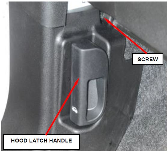
Figure 1 – Hood Latch Screw
- Remove and save the screw located behind the hood latch handle (Figure 1).
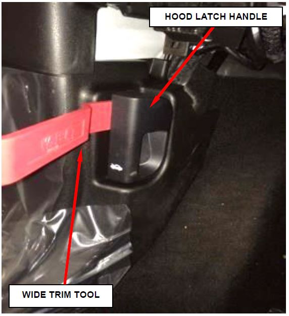
- Using a wide trim tool or equivalent, remove the hood latch handle (Figure 2).
NOTE: Apply even pressure across the top and bottom of the hood latch handle to prevent damage to the hood release cable.
- Remove the driver’s side floor mat.
Figure 2 – Hood Latch Handle
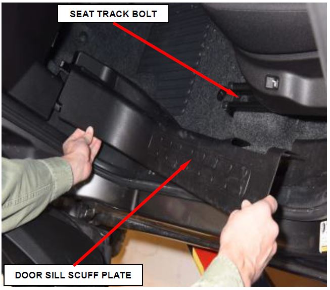
- Remove and save the door sill scuff plate (Figure 3).
- Remove and save the outboard front seat track bolt (Figure 3).
- Remove and save the carpet retaining clip located on top of the seat riser.
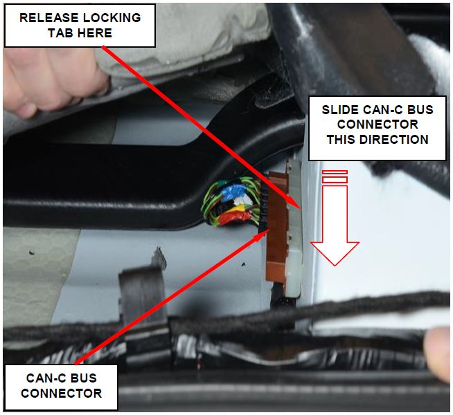
- Lift up carpet or rubber flooring and floor insulation in front of seat riser and position to the side (Figure 4).
- Is the CAN-C Bus connector located on the front side of the driver’s side seat riser as shown in (Figure 4)?
- Yes: Continue with Step 11.
- No: CAN-C Bus connector is not located on the seat riser. No further action is required. Reassemble the vehicle by reversing Steps 1 through 9 of Section A. Inspect CANC Bus Connector. The recall has been completed. Return the vehicle to the customer.
- Slide CAN-C Bus connector toward the driver’s side of vehicle while releasing the locking tab to unhook from seat riser (Figure 4).
Figure 3 – Door Sill Scuff Plate
Figure 4 – CAN–C Bus Connector
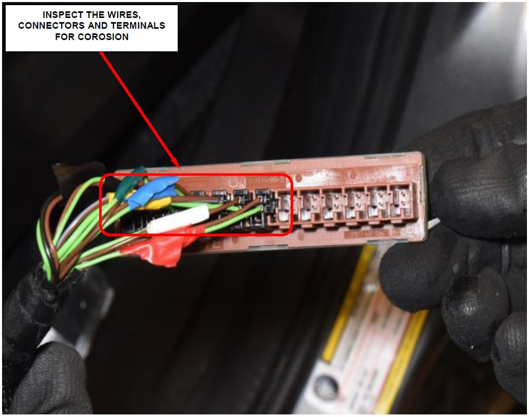
- Inspect the CAN-C Bus Connector to assure there is no corrosion (Figure 5).
- If corrosion is present, continue with Section C. Replace CAN–C Bus Connector.
- If corrosion is not present, continue with Section B. Relocate CAN–C Bus Connector.
Figure 5 – Inspect for Corrosion
B. Relocate CAN–C Bus Connector
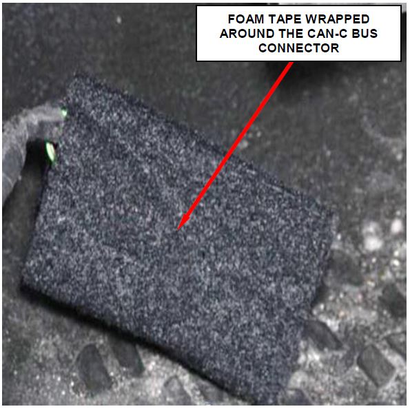
- Apply supplied foam tape on the CAN-C Bus Connector (Figure 6).
CAUTION: While wrapping the CAN-C Bus Connector in foam tape do not disrupt the wire dress orientation.
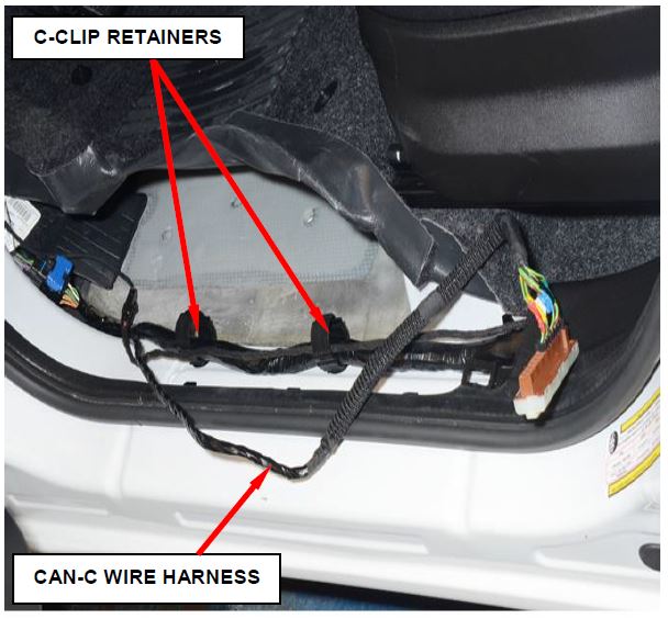
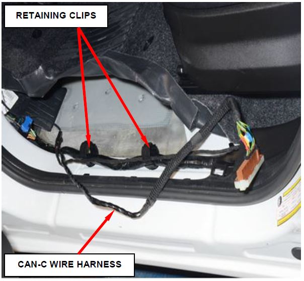
- Release the CAN-C wire harness from the two C-Clip retainers (Figure 7).
- After the CAN-C wire harness is taken out of retaining clips, fasten retaining clips.
Figure 6 – Foam Tape Figure
7 – CAN-C Wire Harness Retainers
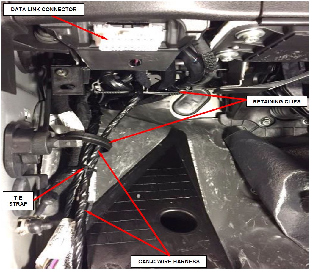
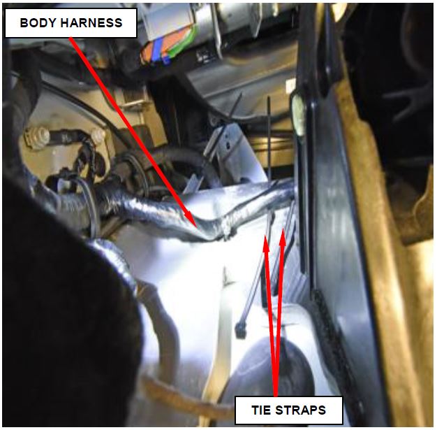
- Route the CAN-C wire harness under the instrument panel and tie strap the wire harness to the body harness (Figure 8).
- Release the retaining clips located near the data link connector (Figure 8).
- Route the CAN-C wire harness through the retaining clips going toward the front of vehicle and close retaining clips (Figure 8).
Figure 8 – CAN-C Wire Harness Routing
- Position two tie straps around body harness on front dash panel as shown (Figure 9).
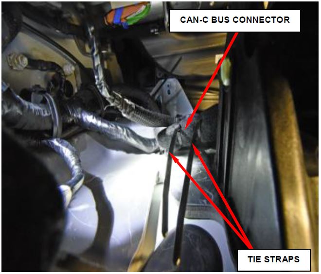
- Fold the CAN-C Bus Connector back on itself and tie strap it to the harness as shown (Figure 10).
Figure 9 – Position Tie Straps
- Cut and discard the excess tie strap.
Figure 10 – CAN-C Harness to Body Harness
- Position the carpet or rubber flooring back into the original position.
- Install the seat track bolt and tighten to 29 ft. lbs. (39 N·m) (Figure 3).
- Install the door sill scuff plate (Figure 3).
- Install the hood latch handle (Figure 2).
- Install the screw located behind the hood latch and tighten securely (Figure 1).
- Install the drive’s side floor mat.
- Connect the negative battery cable.
- Using wiTech scan tool, erase all stored DTC data.
- Return the vehicle to the customer.
C. Replace CAN – C Bus Connector
- Release the CAN-C wire harness from the two C-Clip retainers (Figure 11).
- After the CAN-C wire harness is taken out of retaining clips, fasten retaining clips.
Figure 11 – CAN-C Wire Harness Retainers
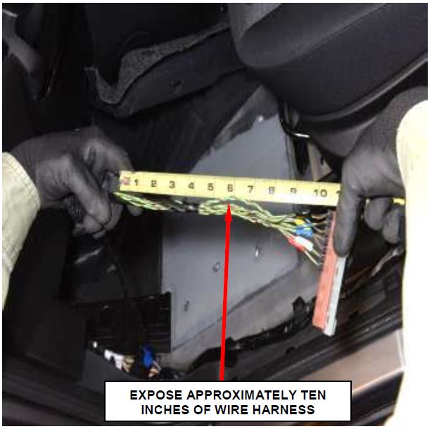
- Remove the tape and slide the protective sleeve approximately ten inches from the CAN-C wire harness to expose the wire harness bundle (Figure 12).
Figure 12 – CAN-C Wire Harness
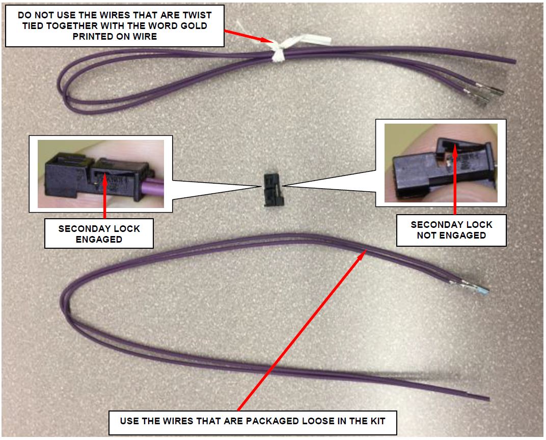
NOTE: Each connector kit contains two sets of wires. Use the wires that are packaged loose in the kit. The gold version terminals are packaged using a twist tie with the word GOLD printed on the wires. DO NOT use the gold version terminals packaged with a twist tie (Figure 13).
SPECIAL NOTE: The word GOLD printed on the wire is extremely small and difficult to read.
- Using the three way connector kit components, build one three-way connector assembly.
- Using the two way connector kit components, build six two-way connector assemblies.
NOTE: When assembling the kit components, ensure the secondary locks are engaged after inserting the terminals into the connectors (Figure 13).
Figure 13 – Two Way Connector Kit Shown
- Use the following procedure to splice the wires together:
NOTE: Splice the wire from Pin 1 of the connector assemblies to the Green wire of the body harness, CAN C (+).
Splice the wire from Pin 2 of the connector assemblies to the Brown wire of the body harness, CAN-C (-).
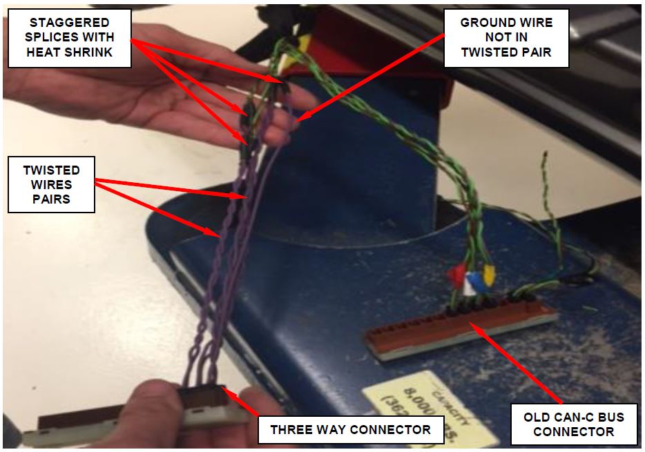
NOTE: Stagger the wire splices to prevent having a large “ball” of wire splices in one location on the wire harness.
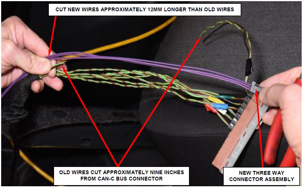
a. Starting with the three way connector assembly cut the wires of the OLD assembly approximately nine inches from the CAN-C Bus connector (Figure 14).
b. Holding the NEW connector assembly to the OLD, cut the NEW wires approximately 12mm longer than the old wires (Figure 14).
c. Strip approximately 10 – 15mm of insulation from the ends of the wires.
Figure 14 – Three Way Assembly
d. Place the black shrink tube provided in the repair kit over the cut wires.
NOTE: All wires of the new CAN-C Bus Connector will be the same color. Be sure to note the correspondence between the locations of the wires in the CAN-C connection with the new CAN-C connection wires.
e. Using the supplied splice band clamps and crimp tool 10042, crimp the two CAN-C wires that had the insulation stripped on the wire harness side to the NEW CAN-C wires (Figure 15).
f. Solder the crimps with rosin core solder.
g. Slide the shrink tube evenly over the splices and apply heat to the shrink tube until glue comes out of both ends of the shrink tube (Figure 15).
h. Twist the two CAN-C wires at a rate of 1 twist per inch. Twist as many times as necessary to achieve and hold the one twist per inch requirement (Figure 15).
i. Insert the three way connector assembly into the NEW CAN-C Bus connector.
Figure 15 – Splice Wires One at a Time
j. Using the supplied splice band clamp and crimp tool 10042, crimp the black ground wire to the remaining three way wire.
k. Solder the crimps with rosin core solder.
l. Slide the shrink tube evenly over the splice and apply heat to the shrink tube until glue comes out of both ends of the shrink tube (Figure 15).
m. Repeat Steps 6a through 6i on the remaining six NEW two way connector assemblies.
NOTE: Begin with the two way connector assembly closest to the three way connector assembly and work your way out.
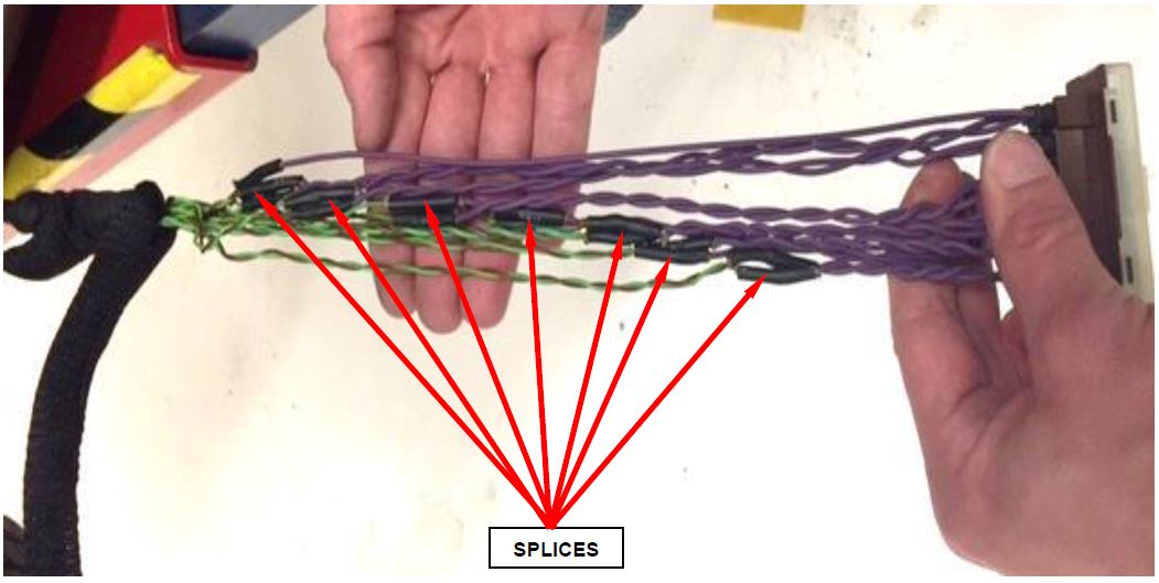
CAUTION: Be sure to stagger the splice joints to prevent a large “ball” of wire splices in one location on the wire harness (Figure 16).
- Using electrical tape, wrap exposed wires and positon the protective sleeve over the CAN-C wire harness.
- Continue with Section B. Relocate CAN–C Bus Connector.
Figure 16 – Stagger Splices
Completion Reporting and Reimbursement
Claims for vehicles that have been serviced must be submitted on the DealerCONNECT Claim Entry Screen located on the Service tab. Claims submitted will be used by FCA to record recall service completions and provide dealer payments.
Use one of the following labor operation numbers and time allowances:
| Labor Operation Number | Time Allowance | |
|---|---|---|
| Inspect CAN-C Bus Connector location | 08-S2-41-81 | 0.2 hours |
| Inspect and Relocate CAN-C Bus Connector (Connector not Corroded) | 08-S2-41-82 | 0.5 hours |
| Inspect, Replace and Relocate CAN-C Bus Connector (Connector Corroded) | 08-S2-41-83 | 1.5 hours |
Add the cost of the recall parts package plus applicable dealer allowance to your claim.
NOTE: See the Warranty Administration Manual, Recall Claim Processing Section, for complete recall claim processing instructions.
Dealer Notification
To view this notification on DealerCONNECT, select “Global Recall System” on the Service tab, then click on the description of this notification.
Owner Notification and Service Scheduling
All involved vehicle owners known to FCA are being notified of the service requirement by first class mail. They are requested to schedule appointments for this service with their dealers. A generic copy of the owner letter is attached.
Enclosed with each owner letter is an Owner Notification postcard to allow owners to update our records if applicable.
Vehicle Lists, Global Recall System, VIP and Dealer Follow Up
All involved vehicles have been entered into the DealerCONNECT Global Recall System (GRS) and Vehicle Information Plus (VIP) for dealer inquiry as needed.
GRS provides involved dealers with an updated VIN list of their incomplete vehicles. The owner’s name, address and phone number are listed if known. Completed vehicles are removed from GRS within several days of repair claim submission.
To use this system, click on the “Service” tab and then click on “Global Recall System.” Your dealer’s VIN list for each recall displayed can be sorted by: those vehicles that were unsold at recall launch, those with a phone number, city, zip code, or VIN sequence.
Dealers must perform this repair on all unsold vehicles before retail delivery. Dealers should also use the VIN list to follow up with all owners to schedule appointments for this repair.
Recall VIN lists may contain confidential, restricted owner name and address information that was obtained from the Department of Motor Vehicles of various states. Use of this information is permitted for this recall only and is strictly prohibited from all other use.
Additional Information
If you have any questions or need assistance in completing this action, please contact your Service and Parts District Manager.
Customer Services / Field Operations
FCA US LLC
CAN-C BUS CONNECTOR
IMPORTANT SAFETY RECALL
S24 / NHTSA 16V-202
This notice applies to your vehicle (VIN: xxxxxxxxxxxxxxxxx).
This notice is sent to you in accordance with the National Traffic and Motor Vehicle Safety Act.
Dear: (Name)
FCA has decided that a defect, which relates to motor vehicle safety, exists in certain 2015 through 2016 model year RAM ProMaster City vehicles.
| The problem is… | The CAN-C bus communication connector on your vehicle may develop internal connector pin corrosion due to moisture intrusion. Corroded CAN-C bus communication connector pin(s) could lead to a loss of electrical contact and/or a loss of communication to the Transmission Control Module (TCM). A loss of communication to the TCM could cause the transmission to perform an unrequested shift into neutral. The vehicle operator would be unable to reengage the transmission. This could cause a crash without warning. |
| What your dealer will do… | FCA will repair your vehicle free of charge. To do this, your dealer will inspect the
CAN-C bus communication connector for pin corrosion. Vehicles found with corroded CAN-C bus connector pin(s) must have the connector replaced. All involved vehicles must also have the CAN-C bus communication connector relocated to a new location under the instrument panel. The work will take about 2 hours to complete. However, additional time may be necessary depending on service schedules. |
| What you must do to ensure your safety… | Simply contact your Authorized BusinessLINK dealer right away to schedule a service appointment. Ask the dealer to hold the parts for your vehicle or to order them before your appointment. Please bring this letter with you to your dealer. |
| If you need help…
| If you have questions or concerns which your dealer is unable to resolve, please contact the FCA Group Recall Assistance Center at either fcarecalls.com or 1-800-853-1403. |
Please help us update our records by filling out the attached prepaid postcard if any of the conditions listed on the card apply to you or your vehicle. If you have further questions go to fcarecalls.com.
If you have already experienced this specific condition and have paid to have it repaired, you may visit www.fcarecallreimbursement.com to submit your reimbursement request online or you can mail your original receipts and proof of payment to the following address for reimbursement consideration: FCA Customer Assistance, P.O. Box 21-8004, Auburn Hills, MI 48321-8007, Attention: Recall Reimbursement. Once we receive and verify the required documents, reimbursement will be sent to you within 60 days. If you’ve had previous repairs and/or reimbursement you may still need to have the recall repair performed on your vehicle.
If your dealer fails or is unable to remedy this defect without charge and within a reasonable time, you may submit a written complaint to the Administrator, National Highway Traffic Safety Administration, 1200 New Jersey Ave., S.E., Washington, DC 20590, or you can call the toll-free Vehicle Safety Hotline at 1-888-327-4236 (TTY 1-800-424-9153), or go to safercar.gov.
We’re sorry for any inconvenience, but we are sincerely concerned about your safety. Thank you for your attention to this important matter.
Customer Services / Field Operations
FCA US LLC
Note to lessors receiving this recall: Federal regulation requires that you forward this recall notice to the lessee within 10 days.
 Loading...
 Loading...
