| “This site contains affiliate links for which OEMDTC may be compensated” |
NHTSA Campaign Number: 16V284
Component(s): POWER TRAIN
Potential Number of Units Affected: 1,029
Manufacturer: Chrysler (FCA US LLC)
SUMMARY:
Chrysler Group LLC (Chrysler
 ) is recalling certain model year 2016 Jeep
 Cherokee vehicles manufactured October 3, 2015, to March 22, 2016.
The right halfshaft may have been incorrectly manufactured causing it to fracture without warning.
CONSEQUENCE:
A fractured halfshaft may disconnect from the drive axle, increasing the risk of a crash.
REMEDY:
Chrysler will notify owners, and dealers will replace the right halfshaft, free of charge.
The recall began on June 30, 2016.
Owners may contact Chrysler ’s customer service at 1-800-853-1403.
Chrysler ’s recall number is S39.
NOTES:
Owners may also contact the National Highway Traffic Safety Administration Vehicle Safety Hotline at 1-888-327-4236 (TTY 1-800-424-9153), or go to www.safercar.gov.
Check if your Vehicle has a Recall
June 2016
Dealer Service Instructions for:
Safety Recall S39 / NHTSA 16V-284 Right Front Halfshaft
Models
| 2016 | (KL) | Jeep Cherokee Cherokee |
NOTE: This recall applies only to the above vehicles equipped with a 3.2L gas engine (sales code EHK) built from October 03, 2015 through March 19, 2016 (MDH 100310 through 031905).
| IMPORTANT: Some of the involved vehicles may be in dealer new vehicle inventory. Federal law requires you to complete this recall service on these vehicles before retail delivery. Dealers should also consider this requirement to apply to used vehicle inventory and should perform this recall on vehicles in for service. Involved vehicles can be determined by using the VIP inquiry process. |
Subject
The right front halfshaft on about 1,000 of the above vehicles may not have been heat treated properly during the manufacturing process. An improperly heat treated right halfshaft could fracture without warning. A fractured right halfshaft could damage underbody components and cause a crash without warning.
Repair
The right front halfshaft must be replaced.
Parts Information
| Part Number | Description |
|---|---|
| 52123815AC | Halfshaft, Right (3.2L/FWD) |
| 06507676AA | Nut, Lower Ball Joint |
| 06509898AA | Nut, Hub Nut |
Due to the small number of involved vehicles, no parts will be distributed initially. Dealers should order the halfshaft for each vehicle at the time appointments are scheduled to assure that the part is available when the customer arrives.
Parts Return
No parts return required for this campaign.
Special Tools
The following special tool is required to perform this repair:
| Press, Ball Joint |
| Front Hub Staking |
Service Procedure
A. Replace Right Front Halfshaft
NOTE: Never handle the halfshaft assembly by the inner or outer boots. This can cause damage to the boot, which will allow contaminants to enter the Constant Velocity (CV) joint.
NOTE: The inner tripod joint is designed with a retention feature that prevents the tripod rollers from coming out of the inner joint housing up to a specific load. If this feature is overcome and the rollers are pulled past the retention feature the joint will lock up and no longer function properly. The entire halfshaft assembly must be replaced if this occurs.
- Raise and support the vehicle.
- Remove the right front tire and wheel assembly.
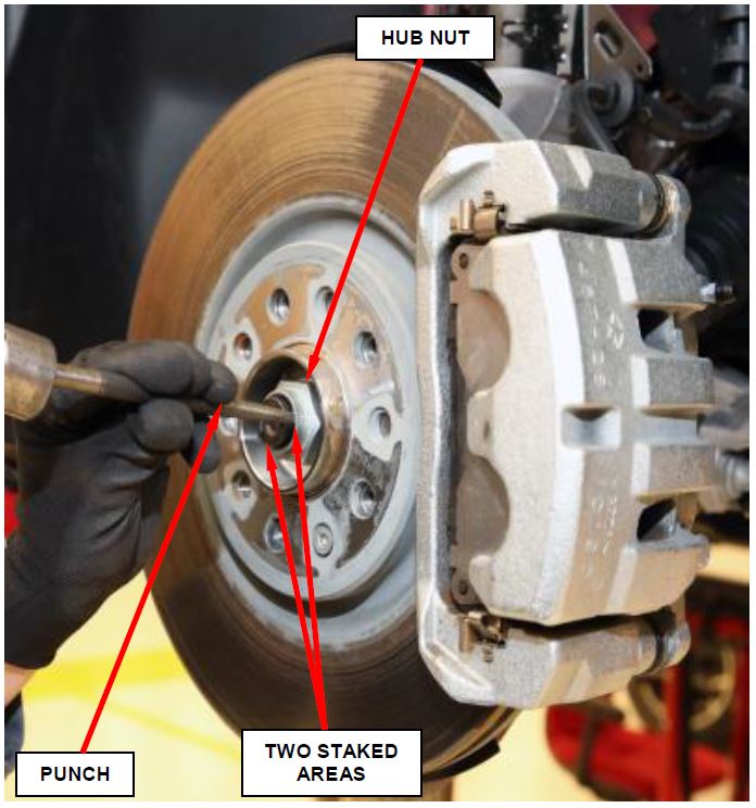
- Using a suitable punch, lift the two staked areas in the hub nut to avoid damaging the halfshaft (Figure 1).
- While a helper applies the brakes to keep the hub from rotating, remove and discard the hub nut from the halfshaft. The original hub nut is not reusable (Figure 1).
Figure 1 – Hub Nut
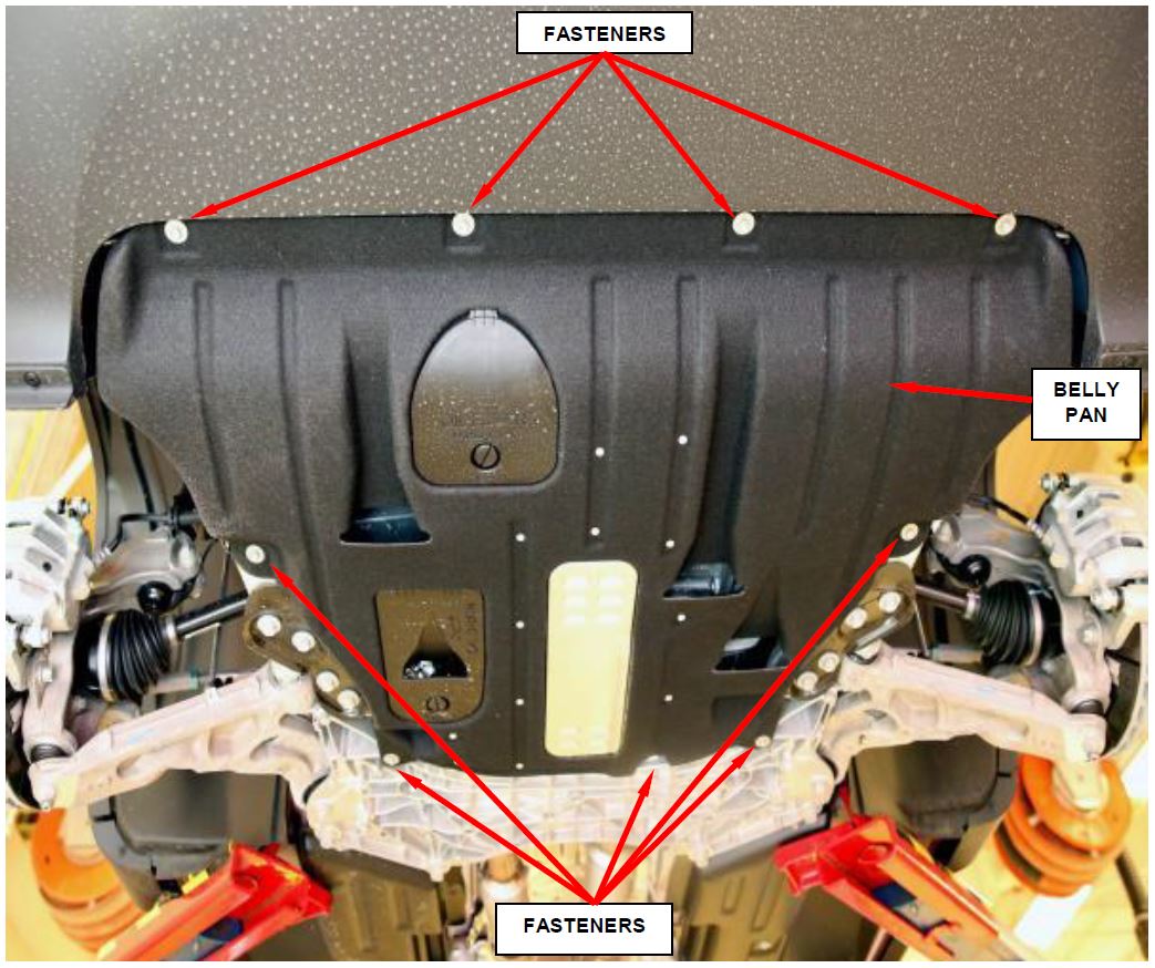
- Remove and save the nine engine belly pan fasteners and remove the belly pan, if equipped (Figure 2).
NOTE: Use care when separating the ball joint stud from the knuckle so the ball joint boot does not get cut.
Figure 2 – Belly Pan
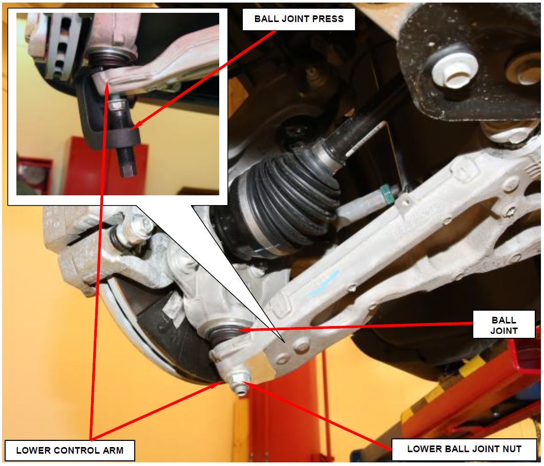
- Remove and discard the lower ball joint nut (Figure 3).
NOTE: Hand start the lower ball joint nut to help protect the lower ball joint thread while using the Ball Joint Press.
- Using the Ball Joint Press C-4150A separate the ball joint stud from the lower control arm (Figure 3).
Figure 3 – Lower Ball Joint
NOTE: After separating the control arm from the knuckle, do not let it swing rapidly back up. This can tear the ball joint dust boot.
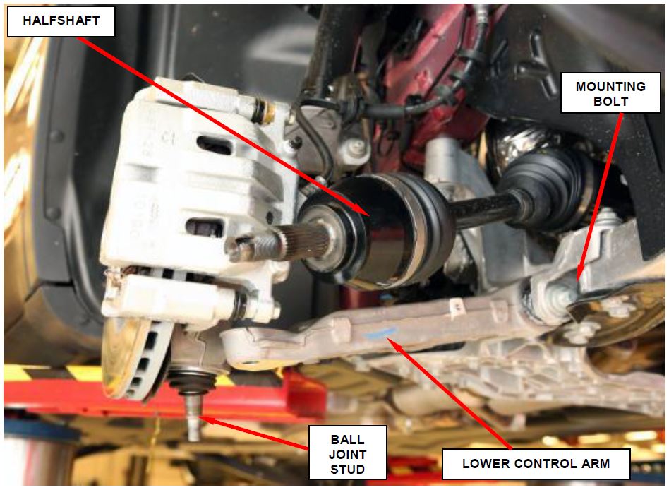
- Insert a pry bar in the opening between the control arm front mounting bolt and the front fascia support beam (Figure 4).
NOTE: The halfshaft may stick in the hub bearing during removal. A dead-blow or plastic hammer can be used to tap the halfshaft inward and out of the hub bearing.
- Pry down on the control arm until the ball joint stud is clear of the control arm. Position the knuckle assembly to the side until it is clear of the ball joint stud. Slowly release the control arm.
- Swing the steering knuckle outward and off the halfshaft end (Figure 4).
Figure 4 – Lower Control Arm
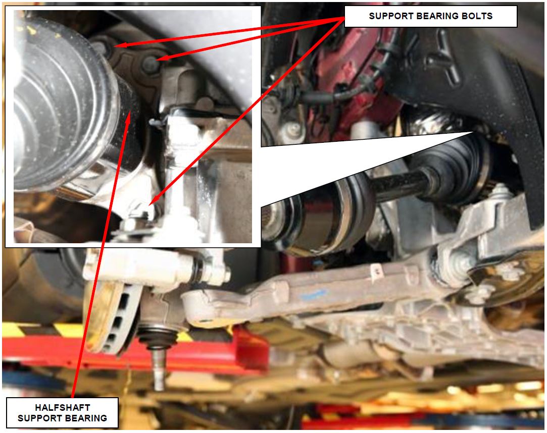
- Remove three bolts holding the support bearing to the engine bracket (Figure 5).
- Separate the support bearing bracket from the engine support bracket and support the halfshaft on a suitable stand.
- Using a pry bar or equivalent tool release the halfshaft from the transaxle and remove the halfshaft from the vehicle.
Figure 5 – Support Bearing Bolts
- Position the NEW halfshaft under the vehicle and over the lower control arm. NOTE: Lightly apply grease to the splines prior to installation.
NOTE: When installing the right halfshaft on All Wheel Drive (AWD) vehicles with a single speed Power Transfer Unit (PTU) and manual transaxle, use care when installing the halfshaft as the shaft must pass through multiple oil seals.
- Install the halfshaft into the transaxle and lightly twist until halfshaft spline slides all the way into the transaxle.
NOTE: If circlip is fully engaged, tripod joint will not be removable from transaxle by hand.
- Swing the steering knuckle outward and engage the halfshaft end into the hub bearing spline.
- Position the intermediate bearing bracket onto the engine support bracket and align the bolt holes.
- Install the three bolts to hold intermediate support bearing to the engine bracket and tighten the bolts to 17 ft. lbs. (24 N•m).
- Push the lower control arm downward until ball joint stud can enter the bottom of the knuckle.
- Insert the ball joint stud into the lower control arm.
- Install a NEW lower ball joint to control arm nut and tighten to 18 ft. lbs. Plus 175° (25 N•m Plus 175°) (Figure 3).
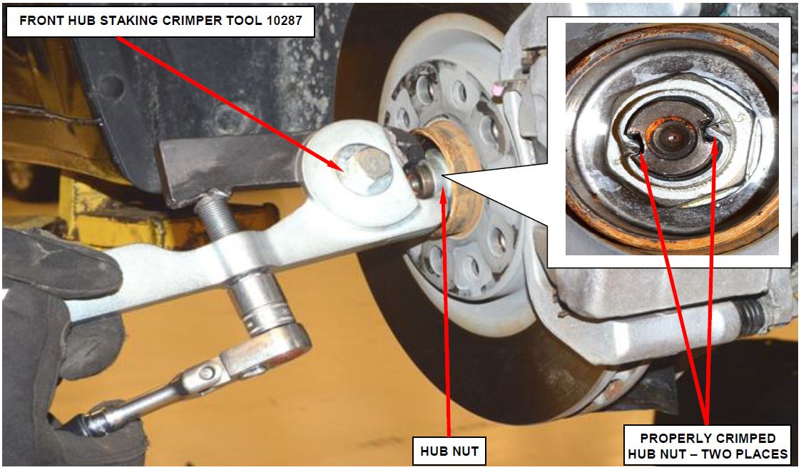
Figure 6 – Crimp Halfshaft Hub Nut with Special Tool 10287
NOTE: Always install a NEW hub nut. The original hub nut is one time use only and must be discarded when removed.
- Install a NEW hub nut and while a helper applies the brakes, tighten the nut to 148 ft. lbs. (200 N•m).
NOTE: Do not use air tools on staking tool while staking hub nut.
- Using the Tool, Front Hub Staking 10287, align the leading cutting edge of Tool, Front Hub Staking 10287 with the top left side channel on axle as shown. Tighten fastener on Tool, Front Hub Staking 10287 with hand tools until the threads bottom out completely (Figure 6).
NOTE: The hub nut must be staked so that it looks similar to Figure 6. Both edges must be split and bent into the shape shown (Figure 6). The staking must be opposite of the direction to tighten the nut.
- If equipped, install the engine belly pan and tighten the fasteners securely (Figure 2).
- Install the tire and wheel assembly and tighten the lugs to 96 ft. lbs. (130 N•m).
- Return the vehicle to the customer.
Completion Reporting and Reimbursement
Claims for vehicles that have been serviced must be submitted on the DealerCONNECT Claim Entry Screen located on the Service tab. Claims submitted will be used by FCA to record recall service completions and provide dealer payments.
Use the following labor operation number and time allowance:
| Labor Operation Number | Time Allowance | |
|---|---|---|
| Replace right front halfshaft | 02-S3-91-82 | 0.5 hours |
NOTE: See the Warranty Administration Manual, Recall Claim Processing Section, for complete recall claim processing instructions.
Dealer Notification
To view this notification on DealerCONNECT, select “Global Recall System” on the Service tab, then click on the description of this notification.
Owner Notification and Service Scheduling
All involved vehicle owners known to FCA are being notified of the service requirement by first class mail. They are requested to schedule appointments for this service with their dealers. A generic copy of the owner letter is attached.
Enclosed with each owner letter is an Owner Notification postcard to allow owners to update our records if applicable.
Vehicle Lists, Global Recall System, VIP and Dealer Follow Up
All involved vehicles have been entered into the DealerCONNECT Global Recall System (GRS) and Vehicle Information Plus (VIP) for dealer inquiry as needed.
GRS provides involved dealers with an updated VIN list of their incomplete vehicles. The owner’s name, address and phone number are listed if known. Completed vehicles are removed from GRS within several days of repair claim submission.
To use this system, click on the “Service” tab and then click on “Global Recall System.” Your dealer’s VIN list for each recall displayed can be sorted by: those vehicles that were unsold at recall launch, those with a phone number, city, zip code, or VIN sequence.
Dealers must perform this repair on all unsold vehicles before retail delivery. Dealers should also use the VIN list to follow up with all owners to schedule appointments for this repair.
Recall VIN lists may contain confidential, restricted owner name and address information that was obtained from the Department of Motor Vehicles of various states. Use of this information is permitted for this recall only and is strictly prohibited from all other use.
Additional Information
If you have any questions or need assistance in completing this action, please contact your Service and Parts District Manager.
Customer Services / Field Operations
FCA US LLC
RIGHT FRONT HALFSHAFT
IMPORTANT SAFETY RECALL
S39 / NHTSA 16V-284
This notice applies to your vehicle (VIN: xxxxxxxxxxxxxxxxx).
This notice is sent to you in accordance with the National Traffic and Motor Vehicle Safety Act.
Dear: (Name)
FCA has decided that a defect, which relates to motor vehicle safety, exists in certain 2016 model year Jeep Cherokee vehicles.
| The problem is… | The right front halfshaft on your vehicle may not have been heat treated properly during the manufacturing process. An improperly heat treated right halfshaft could fracture without warning. A fractured right halfshaft could damage underbody components and cause a crash without warning. |
| What your dealer will do… | FCA will repair your vehicle free of charge. To do this, your dealer will replace the right front halfshaft. The work will take about one hour to complete. However, additional time may be necessary depending on service schedules. |
| What you must do to ensure your safety… | Simply contact your Chrysler , Jeep , Jeep , Dodge , Dodge or RAM or RAM dealer right away to schedule a service appointment. Ask the dealer to hold the parts for your vehicle or to order them before your appointment. Please bring this letter with you to your dealer. dealer right away to schedule a service appointment. Ask the dealer to hold the parts for your vehicle or to order them before your appointment. Please bring this letter with you to your dealer. |
| If you need help… | If you have questions or concerns which your dealer is unable to resolve, please contact the FCA Group Recall Assistance Center at either fcarecalls.com or 1-800-853-1403. |
Please help us update our records by filling out the attached prepaid postcard if any of the conditions listed on the card apply to you or your vehicle. If you have further questions go to fcarecalls.com.
If you have already experienced this specific condition and have paid to have it repaired, you may visit www.fcarecallreimbursement.com to submit your reimbursement request online or you can mail your original receipts and proof of payment to the following address for reimbursement consideration: FCA Customer Assistance, P.O. Box 21-8004, Auburn Hills, MI 48321-8007, Attention: Recall Reimbursement. Once we receive and verify the required documents, reimbursement will be sent to you within 60 days. If you’ve had previous repairs and/or reimbursement you may still need to have the recall repair performed on your vehicle.
If your dealer fails or is unable to remedy this defect without charge and within a reasonable time, you may submit a written complaint to the Administrator, National Highway Traffic Safety Administration, 1200 New Jersey Ave., S.E., Washington, DC 20590, or you can call the toll-free Vehicle Safety Hotline at 1-888-327-4236 (TTY 1-800-424-9153), or go to safercar.gov.
We’re sorry for any inconvenience, but we are sincerely concerned about your safety. Thank you for your attention to this important matter.
Customer Services / Field Operations
FCA US LLC
Note to lessors receiving this recall: Federal regulation requires that you forward this recall notice to the lessee within 10 days.
 Loading...
 Loading...
