| “This site contains affiliate links for which OEMDTC may be compensated” |
NUMBER: 23-015-15
GROUP: Body
DATE: April 30, 2015
THIS SERVICE BULLETIN IS ALSO BEING RELEASED AS RAPID RESPONSE TRANSMITTAL (RRT) 15-043. ALL APPLICABLE SOLD AND UN-SOLD RRT VIN’s HAVE BEEN LOADED. TO VERIFY THAT THIS RRT SERVICE ACTION IS
APPLICABLE TO THE VEHICLE, USE VIP OR PERFORM A VIN SEARCH IN TECHCONNECT. ALL REPAIRS ARE REIMBURSABLE WITHIN THE PROVISIONS OF WARRANTY.
SUBJECT:
Water Leak – Split Header Seal At End Mold
OVERVIEW:
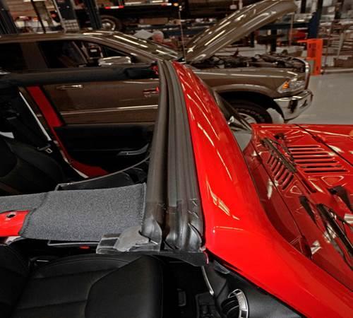
This bulletin involves inspecting/replacing the header seal at the top of windshield frame.
MODELS:
| 2015 | (JK) | Jeep Wrangler Wrangler |
NOTE: This bulletin applies to vehicles built on or after February 04, 2015 (MDH 0204XX) and on or before February 07, 2015 (MDH 0207XX).
SYMPTOM/CONDITION:
Water leak at windshield. The customer may describe water dripping from the top, running down the inside of the windshield, or running down the inside of the A-pillar.
DIAGNOSIS:
If a customer’s VIN is listed in VIP or your RRT VIN list, perform the inspection.
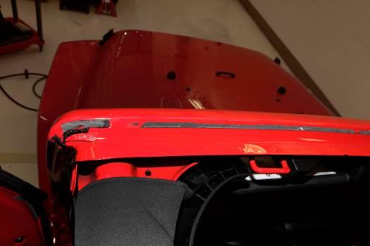
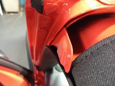
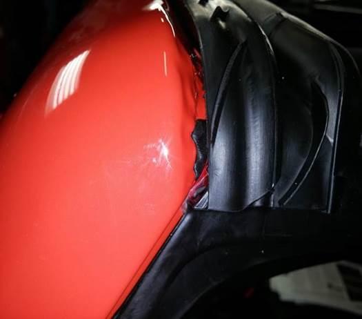
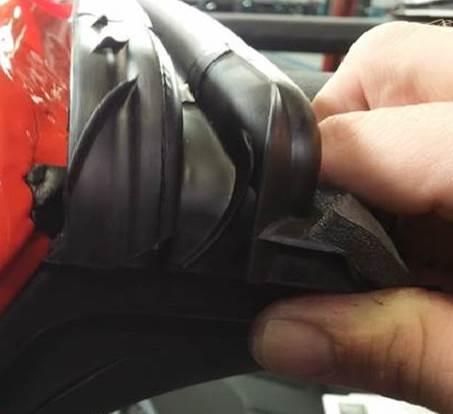
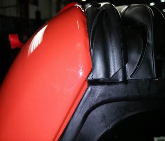
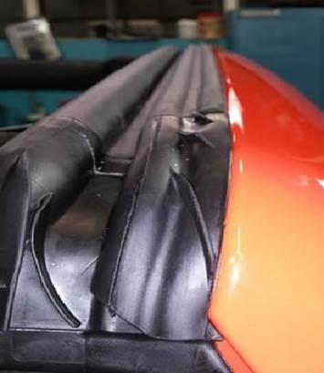
Check for water intrusion at the header seal location. If water is detected open the soft top or remove the hard top to look for a visual split at the header seal at the end molds, If the header seal is split perform the repair.
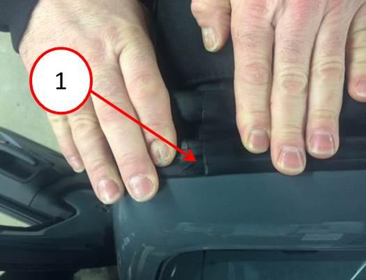
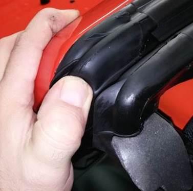
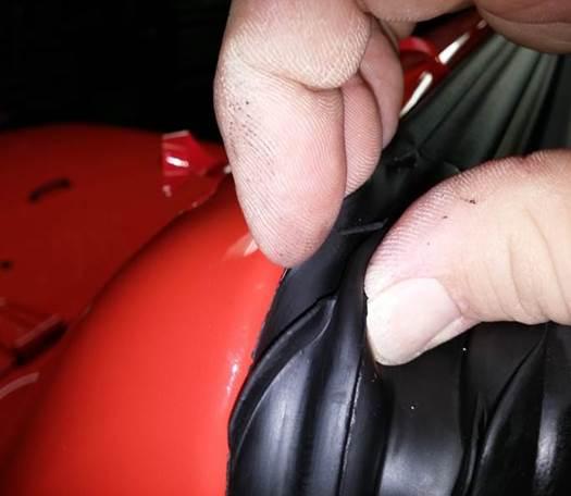
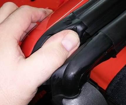
Using two hands, simultaneously apply downward pressure 10 times on each side of the joint line on the seal to check for any splits (Fig. 1). Ensure both sides of the vehicle are checked.
Fig. 1 Header Seal Inspection
1 – Spilt At Header Seal
PARTS REQUIRED:
| Qty. | Part No. | Description |
|---|---|---|
| 1 | 55397454AJ | Seal, Windshield Header |
| 2 | 6036678AA | Rivet, Pop |
SPECIAL TOOLS/EQUIPMENT REQUIRED:
| Equipment | Description |
|---|---|
| NPN | Alcohol Wipes |
| NPN | Rivet Installation Tool |
| NPN | 3M™ 4298 Adhesion Promoter or Equivalent |
| NPN | Small Hand Roller |
REPAIR PROCEDURE:
SEAL REMOVAL
- Remove the freedom panels from the hardtop (if equipped).
- Open the soft top (if equipped).
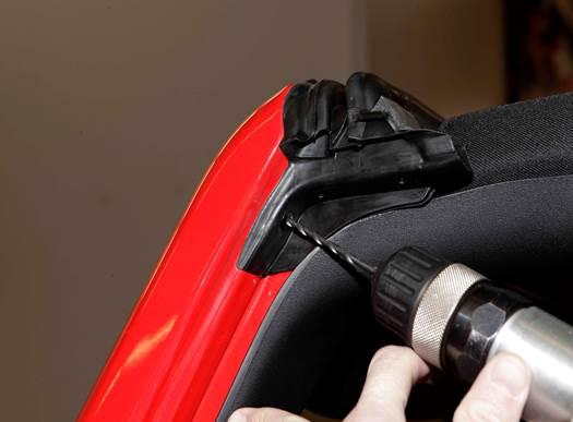
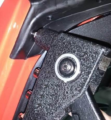
- Using an 1/8 drill bit drill out the head of the side seal rivets on both sides ( 2).
Fig. 2 Drilling out Rivet
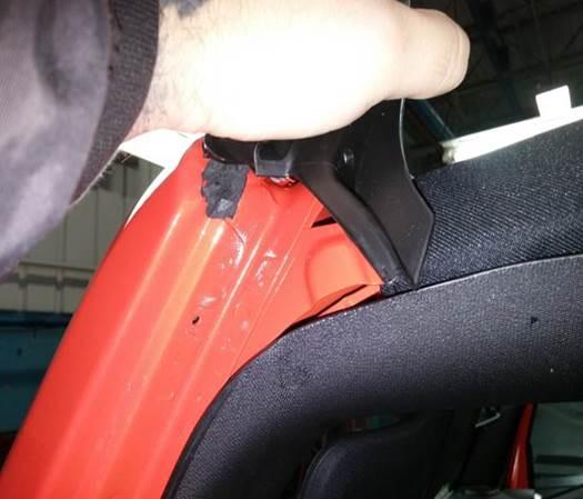
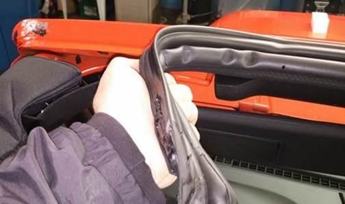
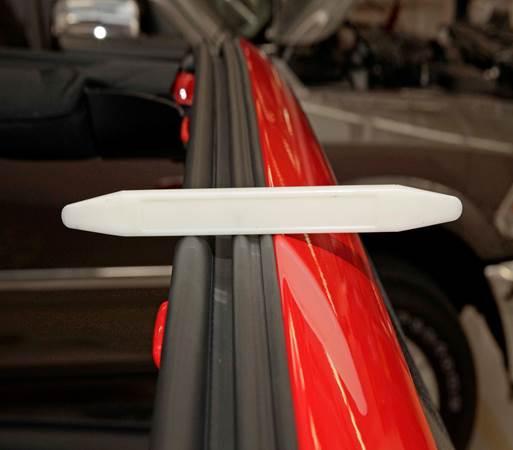
- Lift the side end molds off of the metal support flange (Fig. 3). Carefully pull the seals end mold away from the windshield frame do not pull the seal by the end mold.(Fig. 4).
Fig. 3 End Removal
Fig. 4 Header Seal Removal
PREPARE WINDSHIELD FRAME FOR NEW SEAL
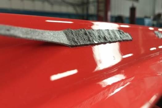
- Remove the extra adhesive tape and the butyl from the windshield header frame (Fig. 5).
Fig. 5 Removing Residue Butyl
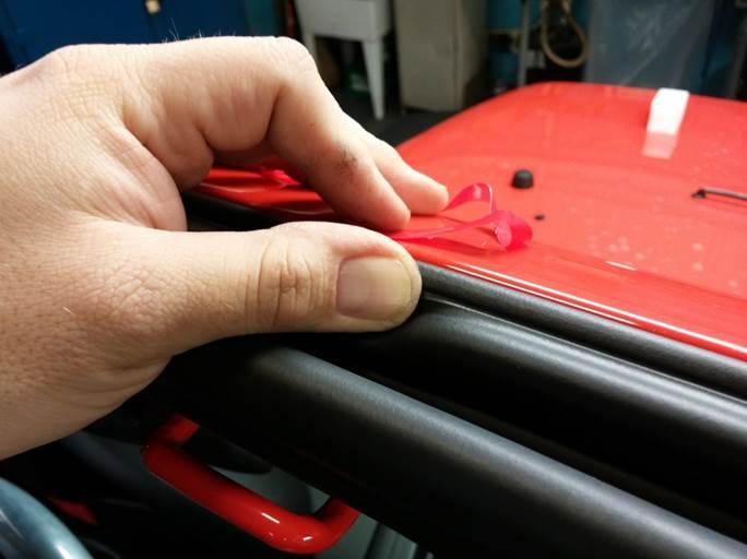
- Pull at a low angle on the remaining adhesive tape (Fig. 6).
Fig. 6 Angle Pull
NOTE: A clean and contaminant free surface is a CRITICAL component of the installation process. The seals adhesive is very sensitive to foreign materials. Failure to properly prepare the surface will result in premature failures.
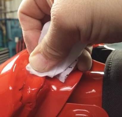
- Using the alcohol wipes, remove the residual butyl from the windshield frame. Be sure to clean thoroughly to ensure proper seal adhesion ( 7).
- Work your way across the windshield frame making sure that there are no remaining contaminants on the sealing surfaces.
Fig. 7 Alcohol Wipe
SEAL INSTALLATION
NOTE: Follow and repeat all these procedures below for the opposite side installation.
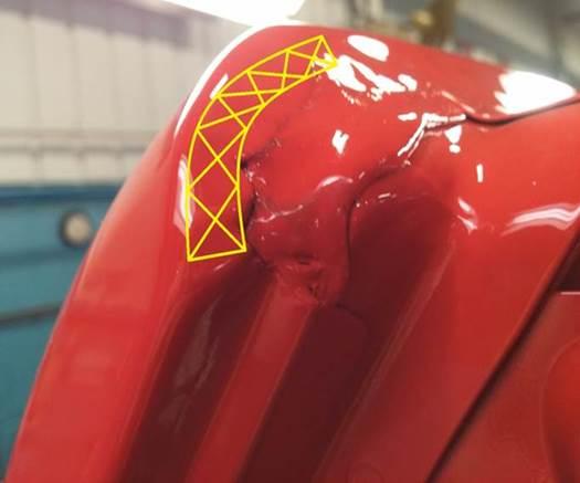
- The butyl square must first be reinstalled on the windshield frame. The yellow lines indicate the path of the seals adhesive tape. The butyl must not obstruct the tape or it will prevent adhesion (Fig. 8).
Fig. 8 Butyl Form Location
- Form a 15mm x 15mm x 1mm piece of butyl and align it as shown on both sides of the windshield frame. Alignment of this patch is critical to avoid interference with the seals adhesive tape (Fig. 9).
Fig. 9 Butyl square
- Wipe the entire windshield header frame where new seal will be applied with 3M™ 4298 Adhesion Promoter or Equivalent (Fig. 10) to ensure proper adhesion of the seal to the metal.
Fig. 10 Adhesion Promoter
- Lay the new windshield to header seal across the side bars of the car loosely (Fig. 11).
Fig. 11 Seal Alignment
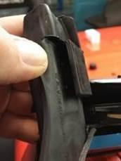
- Make sure that the slot in the back of the seal (Fig. 12) is seated on the reinforcement flange of the windshield frame (Fig. 13).
Fig. 12 End Seal Slot
Fig. 13 Reinforcement Flange
- Align the end mold of the seal so that it matches the profile of the windshield frame. Cross car alignment is critical in preventing leaks (Fig. 14).
- Once the cross car alignment has been established, seat the seal in the middle to ensure the proper position is retained. Do not seat the entire seal at this point.
Fig. 14 Profile Placement
NOTE: If either liner is disturbed, damaged, or missing prior to installation discard the seal. These conditions will result in failure of the seal and water leaks.
- Rock the seal gently backwards allowing room to access the red and blue adhesive liners (Fig. 15).
Fig. 15 Rocking The Seal In Place
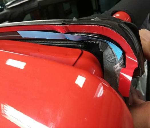
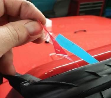
- Carefully pull both release liners until the blue liner is fully removed. Do not continue to pull the red liner past this point. The liners must be carefully pulled directly away from the seal to prevent the butyl from interfering with the adhesive tape (Fig. 16).
Fig. 16 Removing Adhesive Pulls
- Grasp the rear cup of the seals end mold and gently push the seal forward to the frame. Do not allow the adhesive liner contact the windshield frame at this point (Fig. 17).
Fig. 17 Seal Forward
- Be sure that the end mold corner matches the profile of the windshield frame once again before moving forward. Cross car location is critical (Fig. 18).
Fig. 18 Profile Fitment
NOTE: Take care to not touch the adhesive liner as it is sensitive to contaminants.
- Firmly seat the corner of the end mold to the windshield and hold into place (Fig. 19) and use your opposite hand to seat the rest of the end mold to the windshield frame.
Fig. 19 Seal Corner Fitment
NOTE: Take care to not touch the adhesive liner as it is sensitive to contaminants. The pressure specification for seating the adhesive on the seal is a minimum of 5 PSI that is the required force to properly wet out the adhesive tape.
- Apply firm pressure to ensure the butyl is compressed properly (Fig. 20).
Fig. 20 Seating End Piece Seal At Frame
- Firmly compress the butyl along the remainder of the end mold. Be careful not to seat the adhesive tape beyond the mold line in this process (Fig. 21).
Fig. 21 Seal Corner Alignment
NOTE: When the cross car location has been properly set, the holes in the seal and in the windshield frame will align perfectly.
- Install the rivet (Fig. 22) on the side you are working on, rivet should effortlessly slide into place
Fig. 22 Riveting
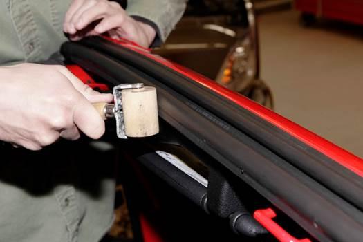
- Seat the seal to the windshield frame flange starting at the outside and working inward using a small hand roller ending at the center. (Fig. 23).
Fig. 23 Smoothing Out Seal
NOTE: The liner should be pulled no more than 2 inches beyond where the seal has been adhered to the frame to prevent an uneven application.
NOTE: Apply an additional firm pass along the entire length of the seal using the small hand roller to help ensure the proper bonding of the adhesive to the windshield frame.
- Begin pulling the red release liner and seating the seal starting at the outside andworking your way to the center (Fig. 24).
- Pull the red liner away as you seat the seals adhesive tape using firm pressure alongthe top of the header seal as shown. Use a small hand roller to ensure the seal remains fully seated on the flange to prevent a low application (Fig. 24).
Fig. 24 Using Roller On Seal
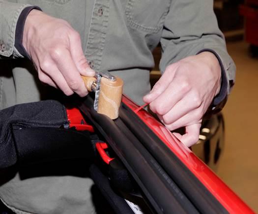
- End at the center of the windshield frame leaving the other half of the tape release liner attached to the seal (Fig. 25). Then repeat steps on the other side of vehicle working from the outside to the center.
Fig. 25 Release Pressure
- The top of the header seal should be close to even with the top of the windshield frame along the entire seal (Fig. 26).
Fig. 26 Level Seal
- A properly installed windshield to header seal will have a uniform height and even appearance along the entire length of the seal, with the seals ends aligning perfectly to the profile of the windshield frame (Fig. 27).
Fig. 27 Properly Aligned Seal
- Allow the seal to set undisturbed for a minimum of 20 minutes before reinstalling thetop(s).
- Close the soft top (if equipped).
- Install the freedom panels back in place to the hard top (if equipped).
- Perform water leak test to verify repair.
POLICY:
Reimbursable within the provisions of the warranty.
TIME ALLOWANCE:
| Labor Operation No: | Description | Skill Category | Amount |
|---|---|---|---|
| 23-51-35-90 | Weatherstrip, Windshield Header Inspect (1 – Semi-Skilled) | 6 – Electrical and Body Systems | 0.3 Hrs. |
| 23-51-35-91 | Weatherstrip, Windshield Header Inspect, Replace and Water Test (1 – Semi-Skilled) | 6 – Electrical and Body Systems | 1.7 Hrs. |
FAILURE CODE:
| ZZ | Service Action |
 Loading...
