| “This site contains affiliate links for which OEMDTC may be compensated” |
NHTSA Campaign Number: 15V826
Component(s): ELECTRICAL SYSTEM , STRUCTURE
Potential Number of Units Affected: 32,784
Manufacturer: Chrysler (FCA US LLC)
SUMMARY:
Chrysler (FCA US LLC) is recalling certain model year 2015-2016 Jeep
 Cherokee vehicles manufactured February 18, 2015, to September 10, 2015 and equipped with the power liftgate option.
In the affected vehicles, water may leak into the Power Liftgate Control Module and result in a high resistance short circuit.
CONSEQUENCE:
A short circuit in the module increases the risk of a fire.
REMEDY:
Chrysler will notify owners, and dealers will inspect the module and connectors for corrosion, replacing the damaged components as necessary.
The mastic shield will be removed and the module will be covered with a water shield.
These repairs will be performed free of charge.
The recall began on February 1, 2016.
Owners may contact Chrysler customer service at 1-800-853-1403.
Chrysler ’s number for this recall is R67.
NOTES:
Owners may also contact the National Highway Traffic Safety Administration Vehicle Safety Hotline at 1-888-327-4236 (TTY 1-800-424-9153), or go to www.safercar.gov.
Check if your Vehicle has a Recall
Dealer Service Instructions for:
January 2016
Safety Recall R67 / NHTSA 15V-826 Power Liftgate Module
Models
| 2015 – 2016 | (KL) | Jeep Cherokee Cherokee |
NOTE: This recall applies only to the above vehicles built from February 18, 2015 through September 09, 2015 (MDH 021800 through 090922).
Subject
The power liftgate control module on about 32,700 of the above vehicles may experience a corrosion induced high resistance short circuit in the power liftgate module electrical connector(s). The power liftgate module electrical connector(s) could allow water intrusion and cause the module to become inoperative and/or cause a fire.
Repair
The power liftgate module must be inspected for evidence of water intrusion and electrical connector corrosion. On vehicles found with corrosion in the power liftgate module electrical connectors, the module and electrical connectors will be replaced.
All involved vehicles will then receive a power liftgate module water shield after repairs are complete.
Alternate Transportation
Dealers should attempt to minimize customer inconvenience by placing the owner in a loaner vehicle if inspection determines that a power liftgate module is required and the vehicle must be held overnight.
Parts Information
| Part Number | Description |
|---|---|
| CBFFR671AA | Shield, Power Liftgate Module Water |
Each dealer to whom vehicles in the recall were assigned will receive enough PLG module water shields to service about 20% of those vehicles.
| Part Number | Description |
|---|---|
| CBNAR273AA | Module, Power Liftgate |
| CBNAR272AA | Power Liftgate Module Connector Package |
| Each package contains the following components: | |
| Quantity | Description |
| 1 | Connector Kit (13 Pin) |
| 1 | Connector Kit (21 Pin) |
| 15 | Bands, Splice |
| 15 | Tube, Shrink |
NOTE: It is expected that less than 600 vehicles globally will require replacement of the Power Liftgate Module (PLG) and electrical connectors. Dealers should NOT order these parts (CBNAR272AA and CBNAR273AA) unless the vehicle is known to have corrosion in the PLG module electrical connector(s). These parts will not be required for most vehicles and will be non-returnable.
| Part Number | Description |
|---|---|
| 04778138 | Tape, Wire Harness |
| 68271635AA | Retainer, Wire Harness |
| 04883971AB | RTV Sealant (MS-GF-44B) |
Parts Return
No parts return required for this campaign.
Special Tools
The following special tools are required to perform this repair:
| wiTECH micro pod II |
| Laptop Computer |
| wiTECH Software |
| 10042 | Crimp Tool |
Service Procedure
A. Power Liftgate (PLG) Module
- Determine the following:
- If the power liftgate is inoperative, continue with Step 2 of this procedure.
- If the power liftgate functions, continue with Section B. Inspect power liftgate module.
- Move the rear seatbacks to the down position to gain access to the rear storage compartment.
- Remove and save the retractable rear shelf curtain.
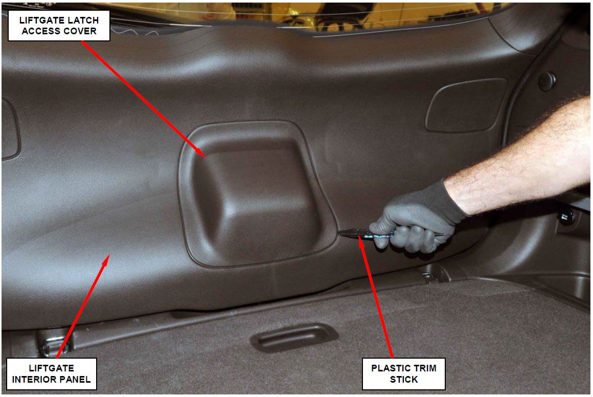
- Using a plastic trim stick, remove and save the liftgate latch access cover (Figure 1).
Figure 1 – Liftgate Access Cover
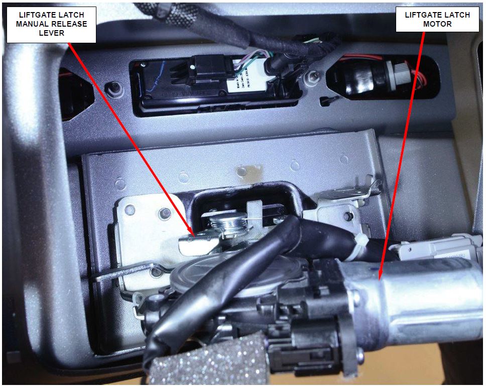
Figure 2 – Latch Release Lever (Looking into Liftgate Opening)
- Pull on the short latch release lever to disengage the liftgate latch and manually open the liftgate (Figure 2).
- Install the original liftgate latch access cover (Figure 1).
- Continue with Section B. Inspect Power Liftgate Module.
B. Inspect Power Liftgate Module
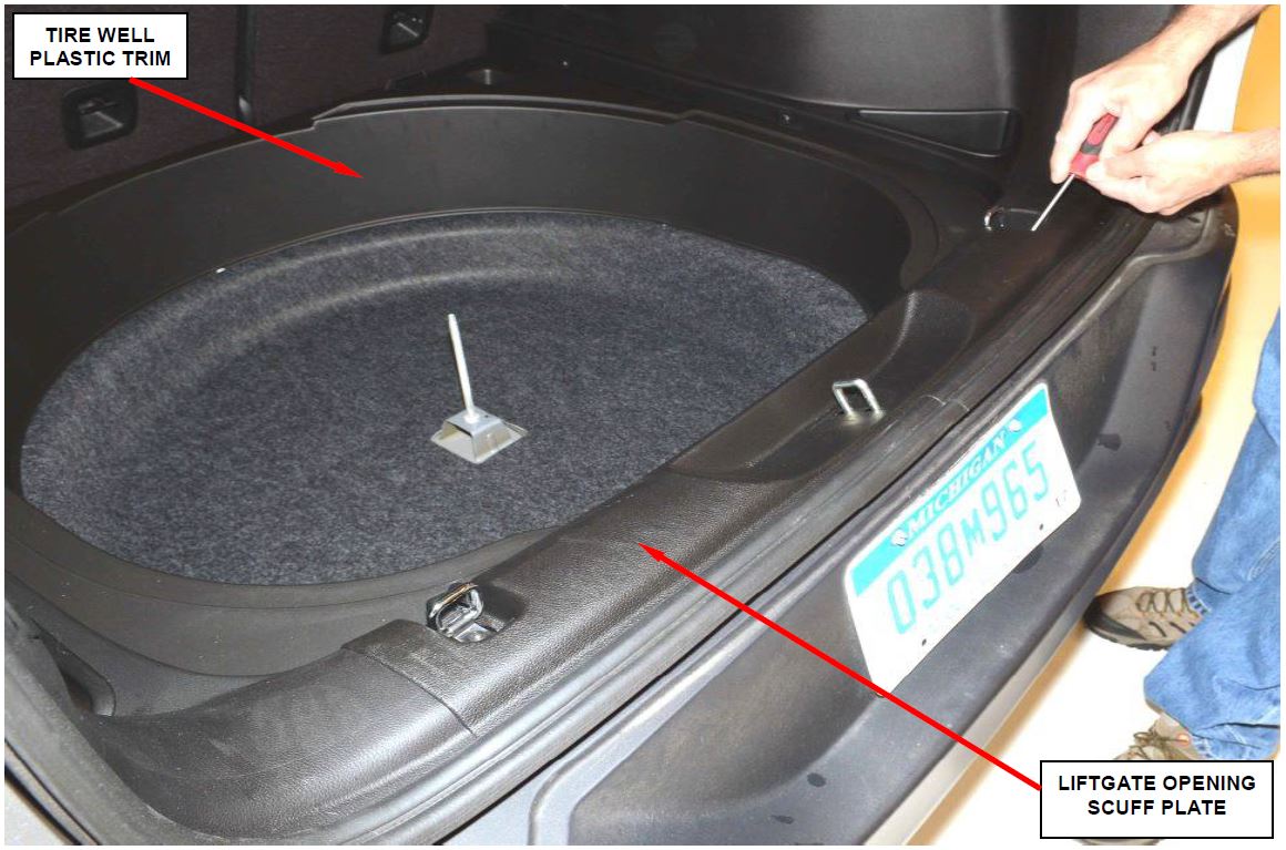
Figure 3 – Scuff Plate and Tire Well Plastic Trim
- Disconnect the negative battery cable.
- If not already performed, remove and save the rear shelf curtain.
- If not already performed, lower the rear seatbacks.
- If equipped, remove and save the load floor mat.
- Remove and the save spare tire/compressor load floor.
- For vehicles with an air compressor, remove and save the air compressor.
- For vehicles with a spare tire, remove and save the spare tire.
- Remove and save the liftgate opening scuff plate (Figure 3).
- Remove and save the tire well plastic trim (Figure 3).
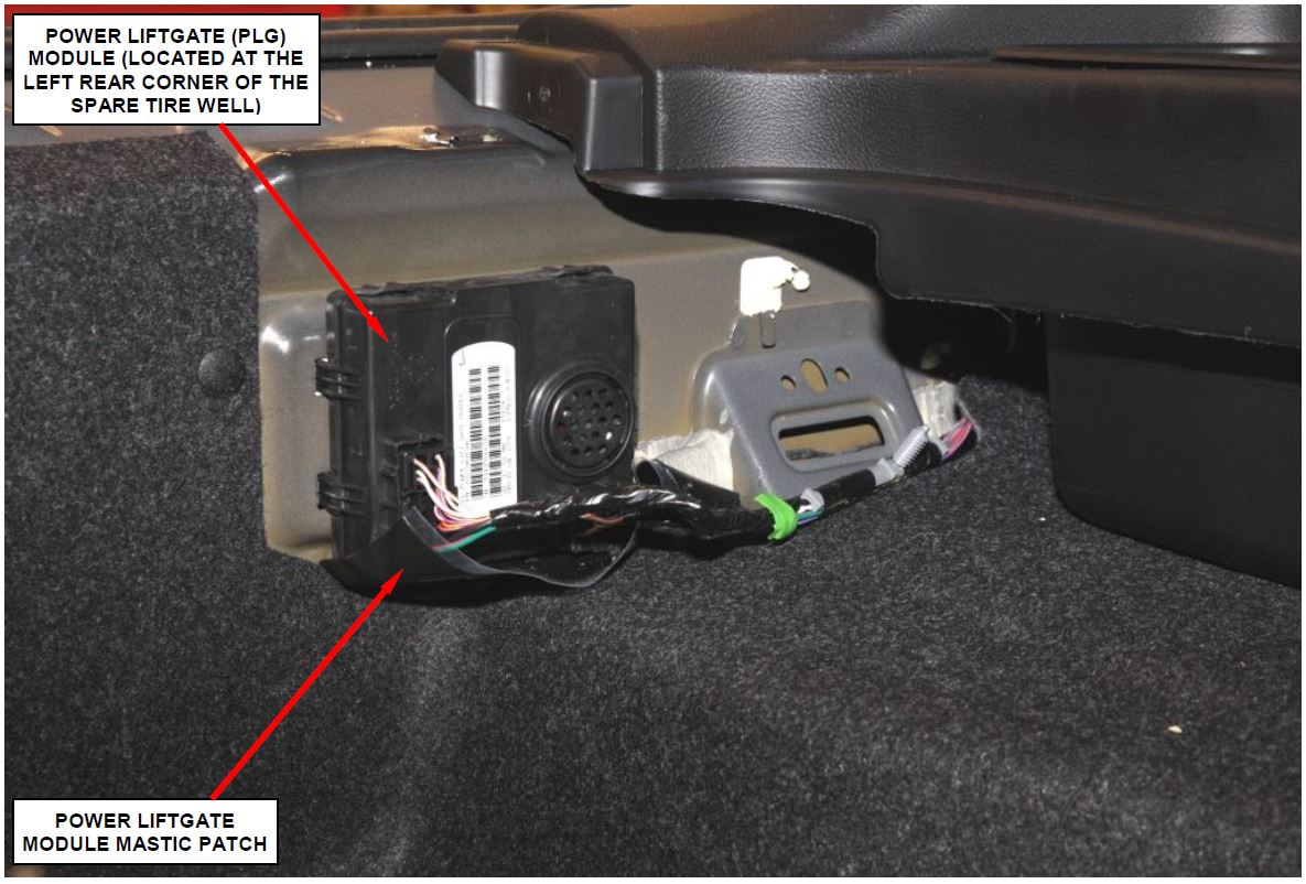
Figure 4 – Remove and Discard Mastic Patch from the PLG Module
- Remove and discard the Power Liftgate Module (PLG) mastic patch(s) (Figure 4).
NOTE: Depending on when the vehicle was built, some vehicles may have two mastic patches. If so, remove and discard both mastic patches.
Figure 5 – Inspect Power Liftgate (PLG) Module Electrical Connectors for Corrosion
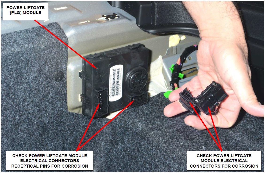
- Disconnect both PLG module electrical connectors (Figure 5).
- Inspect the PLG module electrical connectors for corrosion (Figure 5):
- If there is no corrosion in the PLG module electrical connectors, continue with Section D. – Install Power Liftgate Module Water Shield.
- If there is corrosion in the PLG module electrical connectors, continue with Section C. – Replace Power Liftgate Module and Electrical Connectors.
C. Replace Power Liftgate Module and Electrical Connectors
- Remove and discard the Power Liftgate (PLG) module.
- Remove and save the tire well carpet.
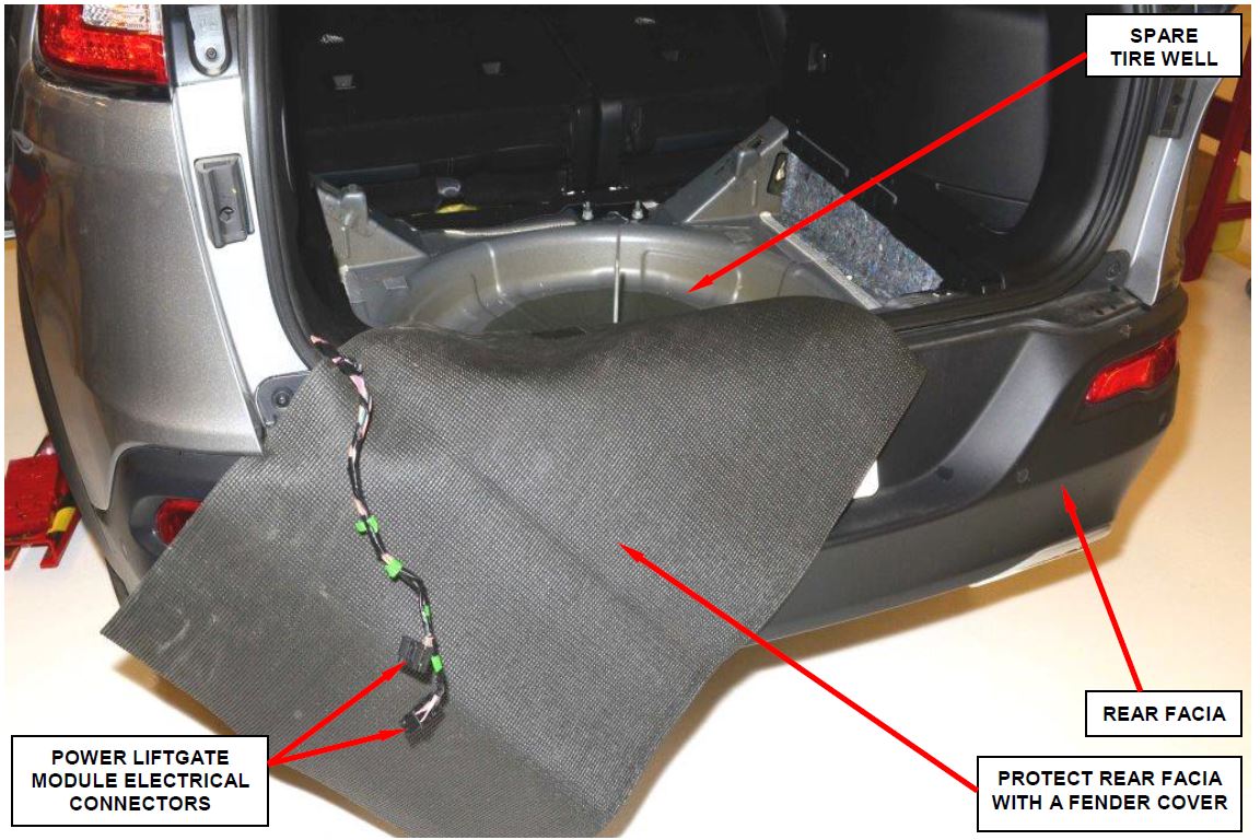
- Disengage the wire harness retaining clips and pull the harness out as shown in Figure 6.
NOTE: Relocating the wire harness as shown will make splicing in the new electrical connectors more accessible.
Figure 6 – Wire Harness Access
Figure 7 – Wire Harness Retainer Locations
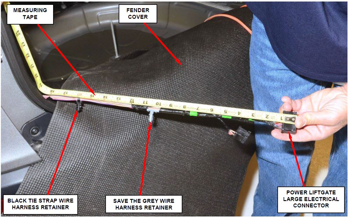
- Measure the wire harness retainer locations on the wire harness (Figure 7). Write down the measurements for future reference.
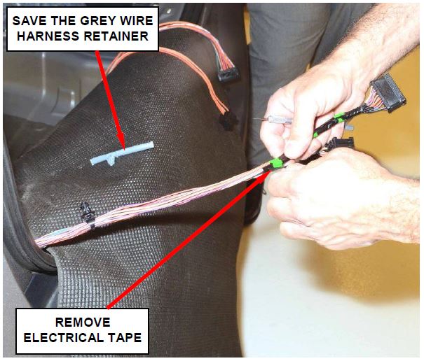
- Remove and discard the wire harness electrical tape (Figure 8).
- Remove and save the grey wire harness retainer (Figures 7 and 8).
Figure 8 – Remove Electrical Tape
- Use the following procedure to splice the new connectors to the body wire harness:
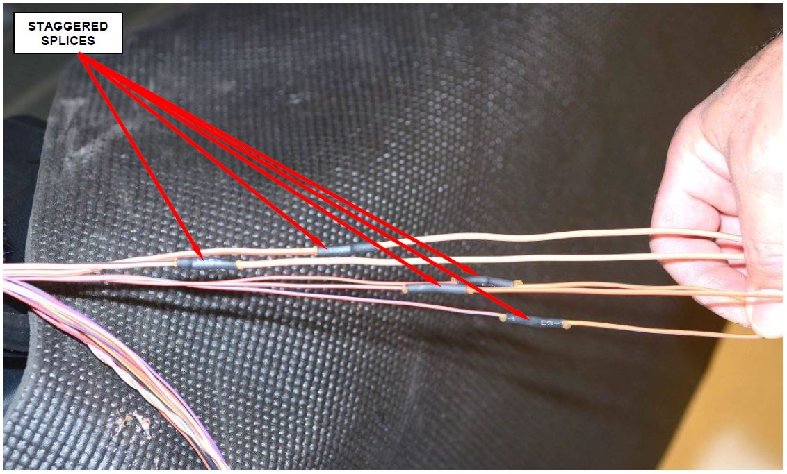
NOTE: Stagger the wire splices to prevent having a large “ball” of wire splices in one location on the wire harness.
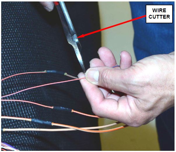
a. Cut the old wire on the electrical connector (Figure 9).
CAUTION: Cut one wire at a time and match the color of the wire cut on the body wire harness to the same color wire on the new connector pigtail.
Figure 9 – Cut Wire (Staggering Cuts)
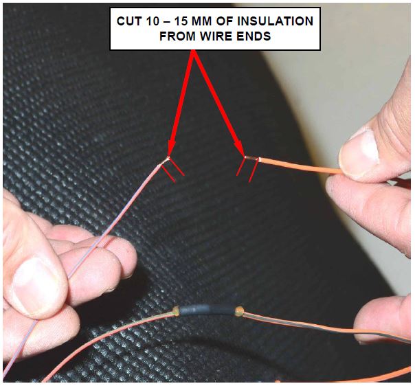
b. Strip approximately 10 – 15mm of insulation from the end of the wires (Figure 10).
Figure 10 – Strip 10 – 15 mm of Insulation from the End of the Wires
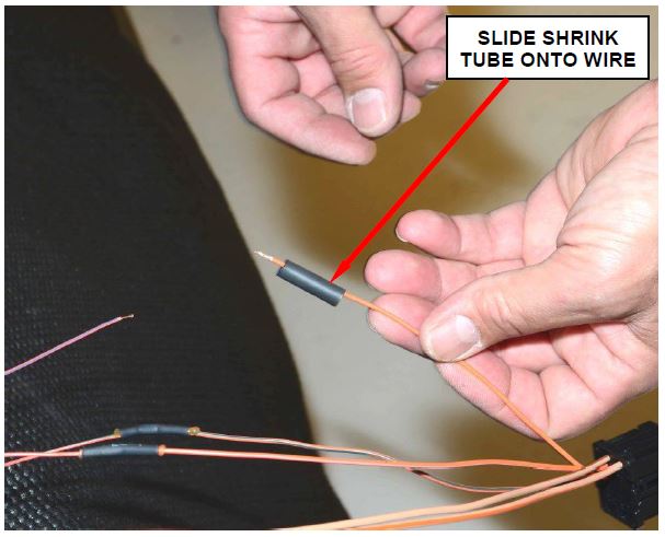
c. Place the black shrink tube provided in the repair kit over the cut wires (Figure 11).
NOTE: The shrink tube for this application is too long. Cut the shrink tube length in half before installing it onto the wire.
Figure 11 – Place Shrink Tube on Wire
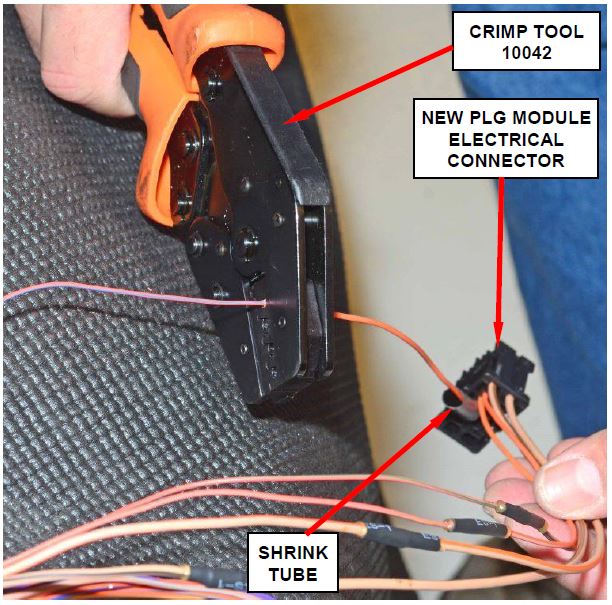
d. Using a brass splice band and crimp tool 10042, crimp the wire harness side wire to the matching color wire on the new connector pigtail (Figure 12).
Figure 12 – Install Brass Crimp
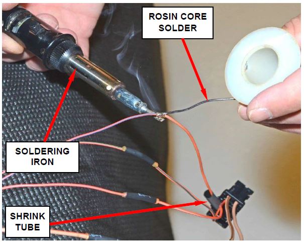
e. Solder the brass crimps with rosin core solder (Figure 13).
Figure 13 – Solder the Brass Crimp
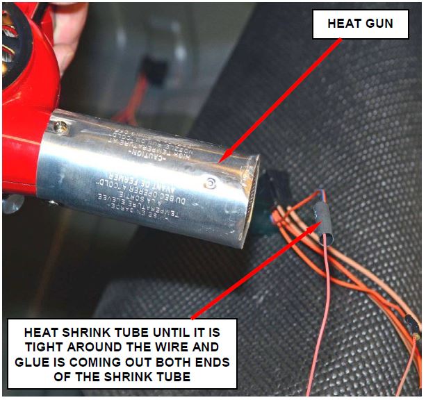
f. Slide the shrink tube over the brass splice band and apply heat until glue comes out of both ends of the shrink tube (Figure 14).
Figure 14 – Apply Heat to Shrink Tube
Figure 15 – Correctly Spliced Wires (Staggered/Crimped/Soldered/Heat Shrink)
g. Repeat Step 7a through 7f on each wire that requires
CAUTION: Be sure to stagger the splice joints to prevent a large “ball” of wire splices in one location on the wire harness (Figure 15).
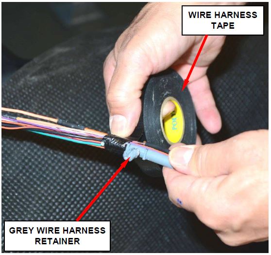
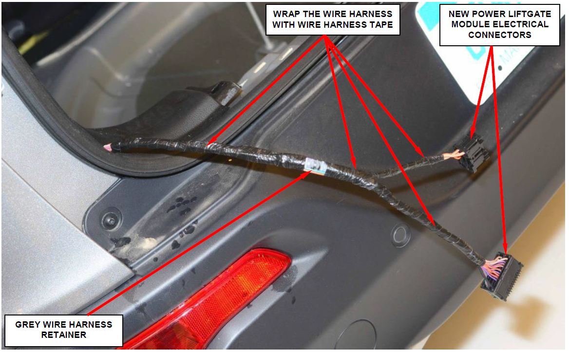
- Tape the grey wire harness retainer to the wire harness in the location measured in Step 4 of this procedure (Figure 16).
Figure 16 – Tape Wire Harness Retainer to Wire Harness
Figure 17 – Wrap Wire Harness with Tape
- Using the supplied wire harness tape, wrap the wire harness (Figure 17).
- Install a black tie strap wire harness retainer to the wire harness in the location measured in Step 4 of this procedure
- Place the wire harness back into position and engage the wire harness retainers in the body panel holes.
- Continue with Section D. – Install Power Liftgate Module Water Shield.
D. Install Power Liftgate Module Water Shield
- If equipped, remove and save the tire well carpet.
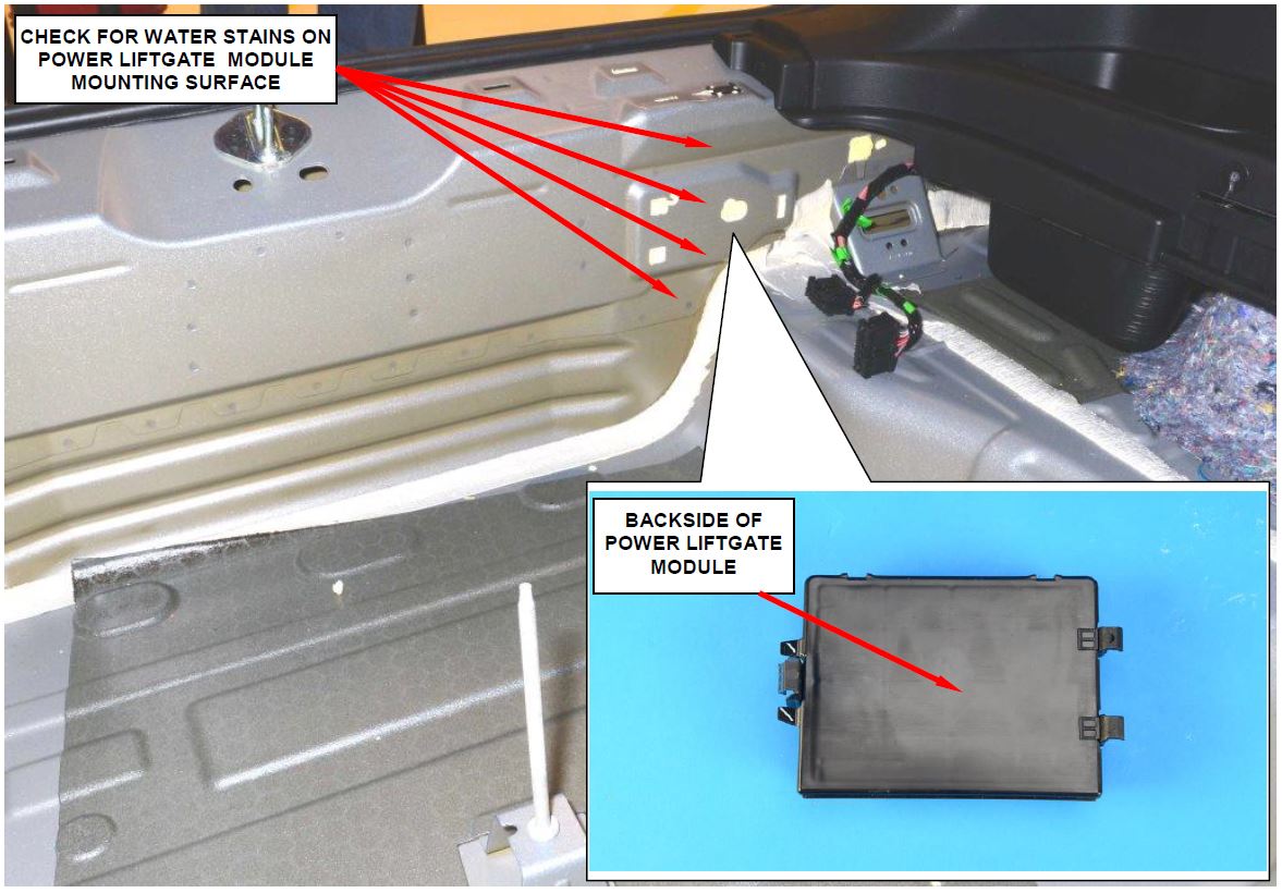
- If the PLG module was not replaced, remove the PLG module and inspect for water intrusion and/or water stains:
- If water stains are not present on the PLG module and/or mounting surface, continue with Step 3 of this procedure (Figure 18).
- If water stains are present on the PLG module and/or mounting surface, discard the original module. The PLG module must be replaced. Then continue with Step 3 of this procedure (Figure 18).
Figure 18 – Check for Water Stains on Backside of PLG Module and/or Mounting Surface
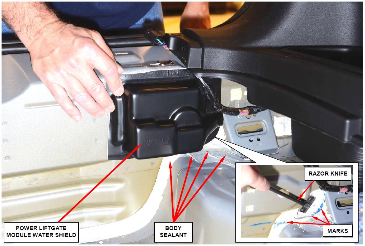
Figure 19 – Test Fit Water Shield and Trim Body Sealer as Required
- Using scissors, trim the glue bead release paper so it is the same size as the water shield (Figure 19).
- Test fit the PLG module water shield. Carefully mark the areas where the body sealer has to be removed (Figure 19).
- Trim the body sealant with a razor knife as required to obtain a flat sealing surface for the water shield glue bead to adhere to on the PLG mounting surface (Figure 19).
- Clean out all body sealant shavings from the tire well.
- Wipe the PLG module mounting panel with an alcohol wipe to ensure that there is no dirt or oil on the panel.
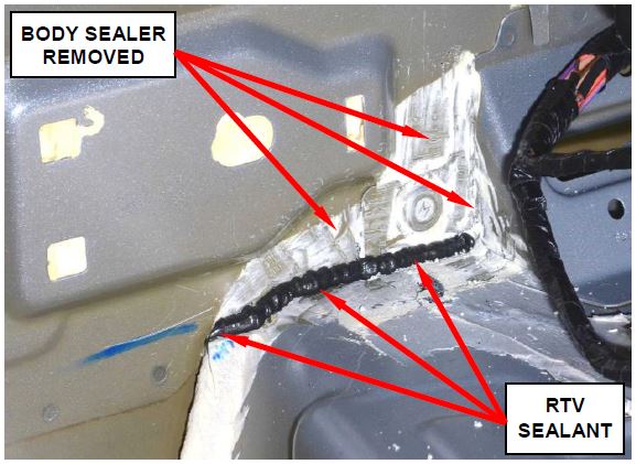
- Using RTV sealant, seal the horizontal panel seam (Figure 20).
Figure 20 – Apply RTV Sealant
- Smooth out the RTV sealant as required.
- Connect the two electrical connectors to the PLG module.
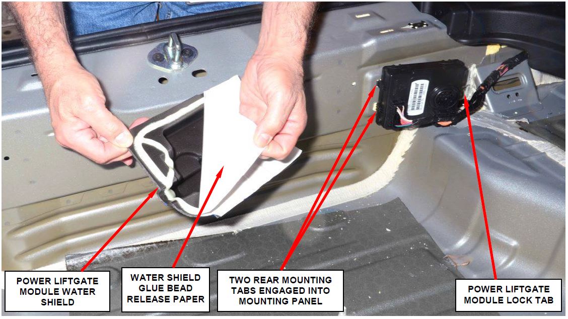
- Partially install the PLG module (rear mounting tabs only) (Figure 21).
- Remove and discard the PLG module water shield glue bead release paper (Figure 21).
Figure 21 – Engage the PLG Module Lock Tab and Install the Water Shield at the Same Time
- Engage the PLG module lock tab and install the water shield at the same time.
- Verify that the water shield glue bead is bonded to the PLG module mounting panel and that the PLG module is snapped into place.
- Install the tire well carpet.
- Install the tire well plastic trim.
- Install the liftgate opening scuff plate.
- For vehicles with a spare tire, install the spare tire.
- For vehicles with an air compressor, install the air compressor.
- Install the spare tire/compressor load floor.
- Install the load floor mat.
- Place the rear seatbacks in the upright position.
- Install the rear shelf curtain.
- Continue with Section E. – Electronic Power Steering Verification Test
E. Electronic Power Steering Verification Test
- Verify all accessories are turned off, the battery is fully charged and the charging system has a status of “charged”.
- Verify that the ignition is “ON”.
- Connect the wiTECH scan tool and start a wiTECH session.
- Using the wiTECH scan tool, record and then erase all Diagnostic Trouble Codes (DTC’s) from all modules.
- Start the engine and allow it to run for two minutes.
- Turn the steering wheel from stop-to-stop twice, holding at each stop position for one second. Then return the steering wheel to the straight ahead position.
- Turn the ignition “OFF” and wait five minutes.
- Turn the ignition “ON” and using the wiTECH scan tool, read DTCs from all modules.
- If there are no DTC’s present after turning ignition “ON”, road test the vehicle for at least five minutes.
- Again, with the wiTECH scan tool, read all If there are no DTC’s present after the road test, the repair is complete.
- Remove the wiTECH scan tool from the vehicle.
- Return the vehicle to the customer. Service Procedure (Continued)
Completion Reporting and Reimbursement
Claims for vehicles that have been serviced must be submitted on the DealerCONNECT Claim Entry Screen located on the Service tab. Claims submitted will be used by FCA to record recall service completions and provide dealer payments.
Use the following labor operation numbers and time allowances:
| Labor Operation Number | Time Allowance | |
|---|---|---|
| Inspect power liftgate module electrical connectors for corrosion and/or water intrusion and install module water shield | 08-R6-71-82 | 1.0 hours |
| Inspect power liftgate module electrical connectors for corrosion and/or water intrusion, replace module, module electrical connectors and install module water shield | 08-R6-71-83 | 2.2 hours |
| Related Operation | ||
| Open inoperative liftgate | 08-R6-71-50 | 0.1 hours |
Add the cost of the recall parts package plus applicable dealer allowance to your claim.
NOTE: See the Warranty Administration Manual, Recall Claim Processing Section, for complete recall claim processing instructions.
Dealer Notification
To view this notification on DealerCONNECT, select “Global Recall System” on the Service tab, then click on the description of this notification.
All involved vehicle owners known to FCA are being notified of the service requirement by first class mail. They are requested to schedule appointments for this service with their dealers. A generic copy of the owner letter is attached.
Enclosed with each owner letter is an Owner Notification postcard to allow owners to update our records if applicable.
Owner Notification and Service Scheduling
All involved vehicles have been entered into the DealerCONNECT Global Recall System (GRS) and Vehicle Information Plus (VIP) for dealer inquiry as needed.
GRS provides involved dealers with an updated VIN list of their incomplete vehicles. The owner’s name, address and phone number are listed if known. Completed vehicles are removed from GRS within several days of repair claim submission.
To use this system, click on the “Service” tab and then click on “Global Recall System.” Your dealer’s VIN list for each recall displayed can be sorted by: those vehicles that were unsold at recall launch, those with a phone number, city, zip code, or VIN sequence.
Dealers must perform this repair on all unsold vehicles before retail delivery. Dealers should also use the VIN list to follow up with all owners to schedule appointments for this repair.
Recall VIN lists may contain confidential, restricted owner name and address information that was obtained from the Department of Motor Vehicles of various states. Use of this information is permitted for this recall only and is strictly prohibited from all other use.
Additional Information
If you have any questions or need assistance in completing this action, please contact your Service and Parts District Manager.
Customer Services / Field Operations
FCA US LLC
POWER LIFTGATE MODULE
IMPORTANT SAFETY RECALL
R67 / NHTSA 15V-826
This notice applies to your vehicle (VIN: xxxxxxxxxxxxxxxxx).
This notice is sent to you in accordance with the National Traffic and Motor Vehicle Safety Act. Dear: (Name)
FCA has decided that a defect, which relates to motor vehicle safety, exists in certain 2015 and 2016 model year Jeep Cherokee vehicles.
| The problem is… | The power liftgate control module on your vehicle may experience a corrosion induced high resistance short circuit in the power liftgate control module electrical connector(s). The power liftgate control module electrical connector(s) could allow water intrusion and cause the module to become inoperative and/or cause a fire. |
| What your dealer will do… | FCA will repair your vehicle free of charge. To do this, your dealer will inspect for evidence of water intrusion and the power liftgate module electrical connectors for corrosion. On vehicles found with corrosion in the power liftgate module electrical connectors, the module and electrical connectors will be replaced.
All involved vehicles will then receive a power liftgate module water shield after repairs are complete. The work will take about 2.5 hours to complete. However, additional time may be necessary depending on service schedules. |
| What you must do to ensure your safety… | Simply contact your Chrysler , Jeep , Jeep , Dodge , Dodge or RAM or RAM dealer right away to schedule a service appointment. Please bring this letter with you to your dealer. dealer right away to schedule a service appointment. Please bring this letter with you to your dealer. |
| If you need help… | If you have questions or concerns which your dealer is unable to resolve, please contact the FCA Group Recall Assistance Center at either recalls.mopar.com or 1-800-853-1403. |
Please help us update our records by filling out the attached prepaid postcard if any of the conditions listed on the card apply to you or your vehicle. If you have further questions go to recalls.mopar.com.
If you have already experienced this specific condition and have paid to have it repaired, you may visit www.fcarecallreimbursement.com to submit your reimbursement request online or you can mail your original receipts and proof of payment to the following address for reimbursement consideration: FCA Customer Assistance, P.O. Box 21-8004, Auburn Hills, MI 48321-8007, Attention: Recall Reimbursement. Once we receive and verify the required documents, reimbursement will be sent to you within 60 days. If you’ve had previous repairs and/or reimbursement you may still need to have the recall repair performed on your vehicle.
If your dealer fails or is unable to remedy this defect without charge and within a reasonable time, you may submit a written complaint to the Administrator, National Highway Traffic Safety Administration, 1200 New Jersey Ave., S.E., Washington, DC 20590, or you can call the toll-free Vehicle Safety Hotline at 1-888-327-4236 (TTY 1-800-424-9153), or go to safercar.gov.
We’re sorry for any inconvenience, but we are sincerely concerned about your safety. Thank you for your attention to this important matter.
Customer Services / Field Operations
FCA US LLC
Note to lessors receiving this recall: Federal regulation requires that you forward this recall notice to the lessee within 10 days.
 Loading...
