| “This site contains affiliate links for which OEMDTC may be compensated” |
NHTSA Campaign Number: 18V556
Manufacturer Chrysler (FCA US LLC)
Components POWER TRAIN
Potential Number of Units Affected 4,171
Rear Axle may Fail Due to Insufficient Oil Level
If the rear axle assembly fails, it can cause a loss of drive or the rear wheels may lock up. Either scenario increases the risk of a crash.
Summary
Chrysler (FCA US LLC) is recalling certain 2018-2019 RAM
 1500 trucks. The rear differential may have been insufficiently filled, possibly resulting in its failure.
Remedy
Chrysler will notify owners, and dealers will inspect the rear axle oil level. Rear axles with an insufficient amount of oil will be replaced, free of charge. The recall is expected to begin October 12, 2018. Owners may contact Chrysler
 customer service at 1-800-853-1403. Chrysler
 ’s number for this recall is U88.
Notes
Owners may also contact the National Highway Traffic Safety Administration Vehicle Safety Hotline at 1-888-327-4236 (TTY 1-800-424-9153), or go to www.safercar.gov.
Check if your Vehicle has a Recall
September 2018
Dealer Service Instructions for:
Safety Recall U88 / NHTSA 18V-556 Rear Axle Fluid Level
Remedy Available
| 2018-2019 | (DS) | RAM 1500 Pickup 1500 Pickup |
NOTE: This recall applies only to the above vehicles built from April 23, 2018 through August 08, 2018 (MDH 042318 through 080809).
| IMPORTANT: Some of the involved vehicles may be in dealer new vehicle inventory. Federal law requires you to complete this recall service on these vehicles before retail delivery. Dealers should also consider this requirement to apply to used vehicle inventory and should perform this recall on vehicles in for service. Involved vehicles can be determined by using the VIP inquiry process. |
Subject
The rear axle assembly on about 4,100 of the above vehicles may have an inadequate oil level which may cause the axle gears and bearings to generate excessive heat and wear, create a whine or growling noise, and the rear axle may fail prematurely. A rear axle assembly that fails prematurely may result in a loss of motive power, and may cause the rear axle to seize. Operating the truck with an inadequate rear axle oil level will result in rear axle gear noise (whine or growling) as a warning prior to rear axle failure. If this warning is not heeded, vehicle crash can occur.
Repair
Inspect all vehicles affected for rear axle oil level. The rear axle will be replaced on those vehicles found with no, or low, oil.
Alternate Transportation
Dealers should attempt to minimize customer inconvenience by placing the owner in a loaner vehicle if inspection determines that a Rear Axle Assembly is required and the vehicle must be held overnight.
Parts Information
Rear Axle Assembly Replacement Parts:
NOTE: The parts below should be ordered only after the axle fluid level inspection determines that a rear axle replacement is required. Very few vehicles are expected to require rear axle assembly replacement.
| Description | Quantity Required | Part Number |
|---|---|---|
| Gasket, Brake Hose to Caliper | 4 | 06502114 |
| Bolt, Propeller Shaft Flange | 4 | 06506497AA |
| Bolt, Upper and Lower Control Arm | 4 | 06509206AA |
| Nut, Upper and Lower Control Arm | 4 | 06104720AA |
| Bolt, Track Bar | 1 | 06104264AA |
| Nut, Track Bar Flag | 1 | 06511267AA |
| Clamp, Axle Vent Hose | 1 | 06503573 |
| Fluid, Brake DOT3 (MS-4574) | 1 | 04318080AD |
Parts Information (Continued)
NOTE: The appropriate rear axle assembly should be ordered only after the axle fluid level inspection determines that a rear axle replacement is required. Very few vehicles are expected to require rear axle assembly replacement.
| Description | Part Number |
|---|---|
| Rear Axle Assembly (3.21 ratio / sales code DMC and DS8) | 68334751AD |
| Rear Axle Assembly (3.21 ratio / sales code DMC and DSA) | 68334755AD |
| Rear Axle Assembly (3.55 ratio / sales code DMD and DS8) | 68334752AD |
| Rear Axle Assembly (3.55 ratio / sales code DMD and DSA) | 68334756AD |
| Rear Axle Assembly (3.92 ratio / sales code DMH and DS8) | 68334753AD |
| Rear Axle Assembly (3.92 ratio / sales code DMH and DSA) | 68334757AD |
NOTE: Sales code DSA = Limited Slip Differential / DS8 = Open Differential
Parts Return
No parts return required for this campaign.
Special Tools
The following special tools are required to perform this repair:
| wiTECH micro pod II |
| Laptop Computer |
| wiTECH Software |
Service Procedure
A. Inspect Axle Fluid Level
- Raise and support the vehicle on a hoist (preferred flat drive on hoist) the axle must remain at normal level for
- Inspect the rear axle fluid level for being within specifications.
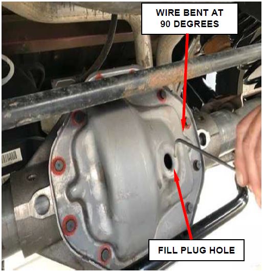
- Clean the area around the fill plug and remove the oil fill plug (Figure 1).
- Take a piece of wire or (zip tie) and make a 90° bend two inches from the end of the wire. Make a line at 6 mm (.25 in or 1/4 in) from the 90° bend for a lubricant level indicator line.
Figure 1 – Fill Plug
- Insert the wire or (zip tie) perpendicular to the fill plug hole and use it like a dipstick. Measure fill level from the bottom of the fill hole.
- Remove the wire or (zip tie) and verify the fluid level is within the marked line from the 90° bend to the oil level.
- Is the rear axle fluid level within specifications?
- YES, no action required. Install the oil fill plug and clean any residual oil from the rear axle cover. Use the inspect LOP to close this recall.
- NO, if equipped with air suspension, proceed to Section Depressurize Air Suspension.
- NO, if not equipped with air suspension, proceed to Section C. Replace Rear Axle Assembly.
B. Depressurize Air Suspension
NOTE: The following procedure is required if the rear axle assembly requires replacement per the inspection in Section “A”. Very few vehicles are expected to require rear axle assembly replacement.
- Open the hood. Install a battery charger
 and verify that the charging rate provides 13.0 to 13.5 volts. Do not allow the charger to time out. Set the battery charger timer (if so equipped) to continuous charge.
NOTE: Use an accurate stand-alone voltmeter. The battery charger volt meter may not be sufficiently accurate. If voltage reading is too high, apply an electrical load by activating the park or headlamps and/or HVAC blower motor to lower the voltage.
- Connect the wiTECH micro pod II to the vehicle data link connector.
- Place the ignition in the “RUN” position.
- Open the wiTECH 2.0 website.
- Enter your “User id” and “Password”, then select “Finish” at the bottom of the screen.
- From the “Vehicle Selection” screen, select the appropriate vehicle.
- From the “Action Items” screen, select the “Topology” tab.
- From the “Topology” screen, select the “ASCM” icon.
- Select the “ Functions” tab.
- Select “Disable Level Control” from the list.
- Follow the screen prompts.
NOTE: Perform the following steps for the left rear and right rear.
- Select “Spring Deflate to Reservoir” from the list.
- Follow the screen prompts.
- Repeat Steps 12 and 13 of this procedure to insure the air suspension is fully deflated.
NOTE: After the rear air springs have the air released, leave the air spring attached to upper spring mount. The air spring does not need to be removed.
C. Replace Rear Axle Assembly
- Use the following procedure to release the transmission manual park release lever:
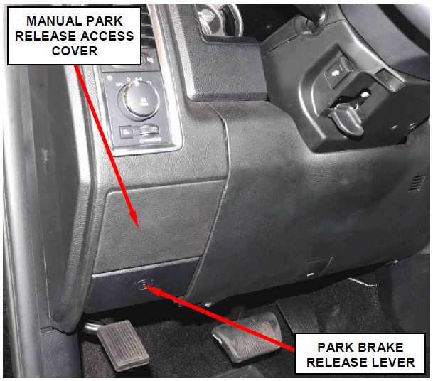
a. Remove and save the transmission manual park release access cover (Figure 2).
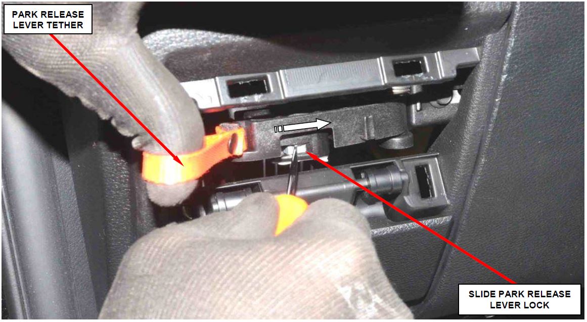
b. Using a small screwdriver, slide the release lever lock to the right and hold in that position (Figure 3).
c. Pull the orange release lever tether to the right until it locks in place (Figure 3).
Figure 2 – Manual Park Release Access Cover
Figure 3 – Transmission Manual Park Release
REMOVAL
- Disconnect the negative battery cable.
- With the vehicle in neutral, position vehicle on hoist.
- Remove both rear tire and wheel assemblies.
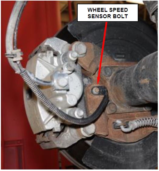
- Remove and save both mounting bolts from the wheel speed sensor (Figure 4).
Figure 4 – Wheel Speed Sensor Bolt
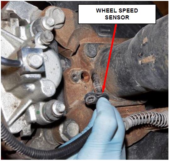
- Remove the wheel speed sensor from the brake caliper adapter (Figure 5).
Figure 5 – Wheel Speed Sensor
NOTE: Do not allow brake hose to support caliper assembly.
NOTE: Mechanics wire can be used to support the caliper and adapter plate assemblies.
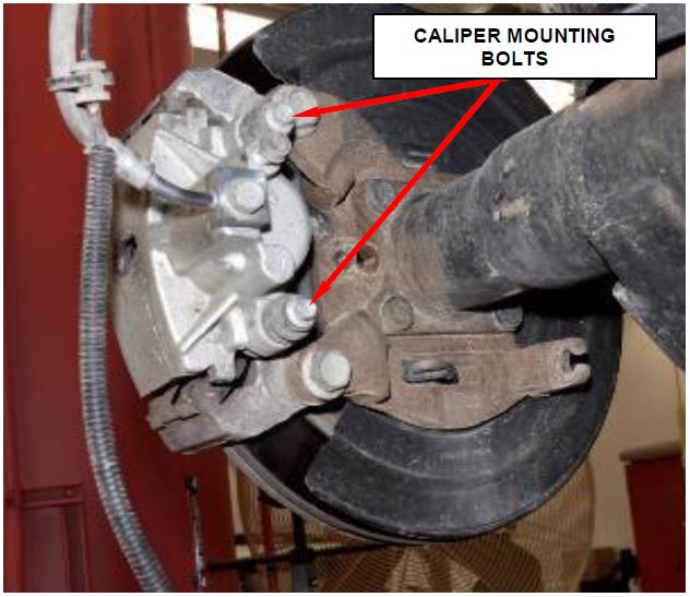
- Remove the brake caliper mounting bolts from the right rear and left rear brake calipers (Figure 6).
Figure 6 – Brake Caliper Bolts
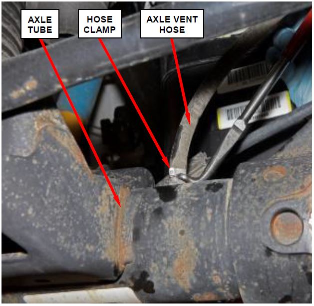
Figure 7 – Axle Vent Hose
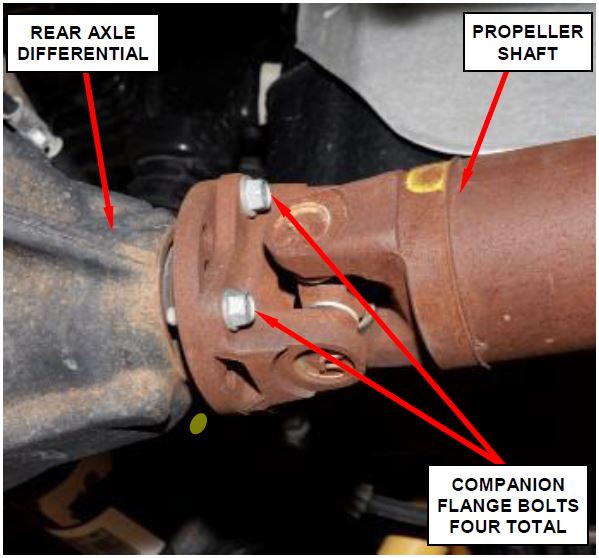
- Remove and DISCARD the rear propeller shaft companion flange bolts (Figure 8).
Figure 8 – Propeller Shaft Bolts
- Suspend the rear propeller shaft using a bungee cord or equivalent.
- Disconnect the rear park brake cables from the rear brakes using the following procedure:
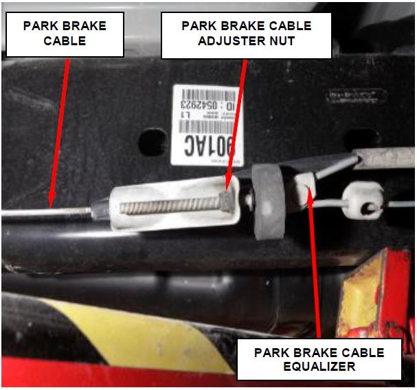
a. Mark the location of the park brake cable adjuster nut (Figure 9).
b. Loosen the park brake cable adjuster nut until the cables are slack (Figure 9).
Figure 9 – Park Brake Cable Adjustment
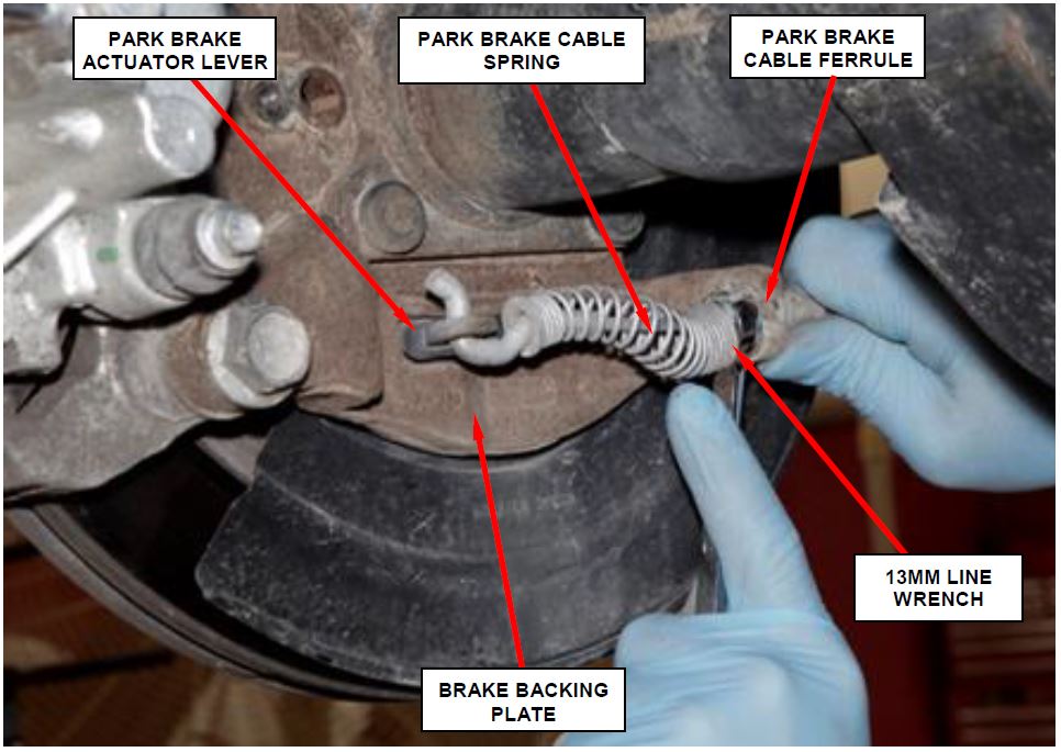
c. Pull the park brake cable spring back (Figure 10).
d. Compress the retaining tabs on each park brake cable ferrule at the brake backing plate using a 13 mm line wrench (Figure 10).
NOTE: A 13mm line wrench can be used to compress the cable ferrule tabs. Insert while spring is pulled back and rotate the wrench to compress the cable ferrule tabs.
e. Remove the park brake cable from the brake backing plate (Figure 10).
f. Remove the park brake cable from the park brake actuator lever (Figure 10).
g. Position the park brake cable away from the rear axle.
Figure 10 – Park Brake Cable
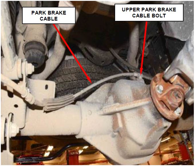
- Remove and save the upper park brake cable bolt from the rear axle (Figure 11).
Figure 11 – Park Brake Cable Bolt
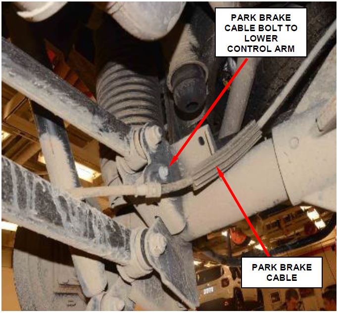
- Remove and save the park brake bolt on the upper control arm bracket (Figure 12).
Figure 12 – Park Brake Cable Bolt
- Position the park brake cable away from the rear axle.
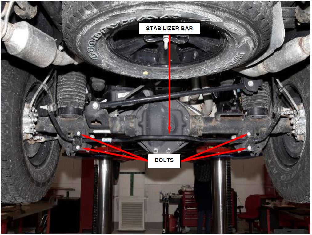
- Remove and save the stabilizer bar bolts and position the stabilizer bar aside or hang from wire off of the spare tire (Figure 13).
Figure 13 – Stabilizer Bar Bolts
- Position a lift under the axle and secure the axle to the lift.
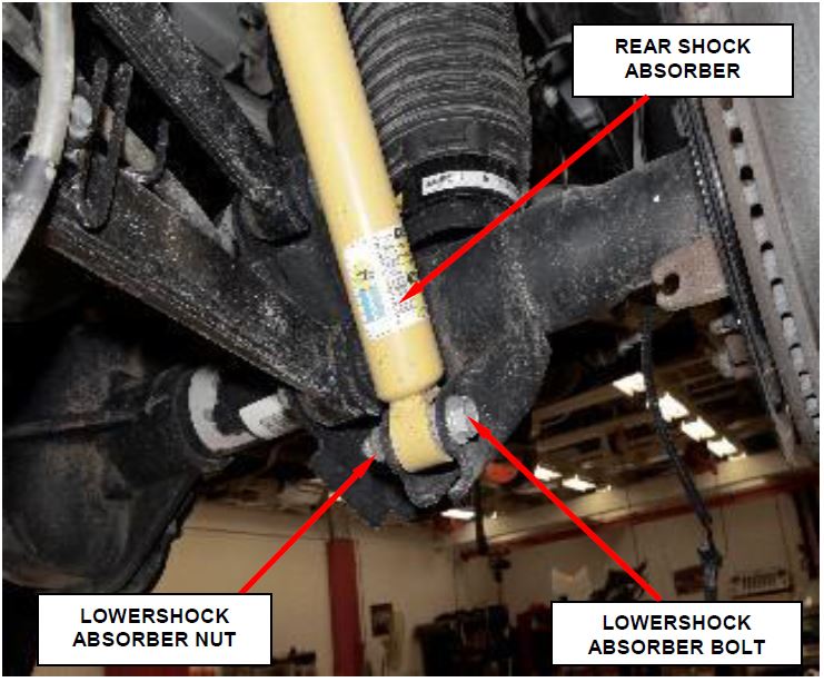
- Remove and save both lower shock absorber bolts and nuts then position the shock absorbers away from the axle (Figure 14).
Figure 14 – Shock Absorber Bolts
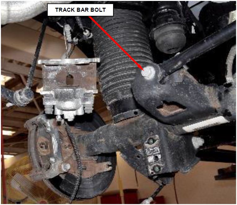
- Remove and DISCARD the track bar bolt and position the track bar away from the rear axle (Figure 15).
Figure 15 – Track Bar Bolt
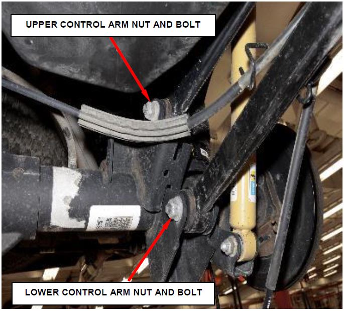
- Remove both the upper control arm to rear axle bolts, DISCARD nut and bolt, and position the upper control arms away from the axle (Figure 16).
- Remove both the lower control arm to rear axle bolts, DISCARD nut and bolt, and position the lower control arms away from the axle (Figure 16).
Figure 16 – Control Arm Bolts
- If equipped with conventional coil springs, slightly lower the rear axle assembly and remove the rear springs.
- Remove the rear axle from the vehicle.
INSTALLATION
NOTE: All suspension torques should be made with the full vehicle weight on the ground being supported by the tires.
- Position the spring and isolator on the axle and align into the spring upper pocket.
- Carefully raise the rear axle into place.
- Position both the lower control arms into the rear axle brackets and loosely install the NEW bolts with NEW nuts.
- Position both the upper control arms into the rear axle brackets and loosely install the NEW bolts with NEW nuts.
- Position the rear track bar to the rear axle bracket and loosely install the NEW bolt.
- Position both the rear shock absorbers to the axle brackets and loosely install the rear shock absorber bolts.
- If equipped, carefully snap the lower end of the left and right height sensor level arms to the ball stud of the lower control arms.
- Remove the axle lift.
NOTE: The stabilizer bar must be centered with equal spacing on both sides.
- Position the stabilizer bar to the rear axle and install and tighten the bolts to 50 N·m (37 ft. lbs.).
- Position the park brake cable back to the rear axle.
- Install the park brake cable bolt on the upper control arm bracket and tighten to 20 N·m (15 ft. lbs.).
- Install the upper park brake cable bolt to the rear axle and tighten to 20 N·m (15 ft. lbs.).
- Install the park brake cable to the park brake actuator lever.
- Pull the park brake cable spring back and install the park brake cable ferrule to the brake backing plate. Ensure that the cable ferrule retaining tabs lock into place on the brake backing plate.
- Tighten the park brake cable adjusting nut until the mark made previously is reached.
CAUTION: Be sure to align the factory alignment paint mark on the propeller shaft as closely to the factory alignment paint mark on the NEW axle companion flange.
- Install the rear propeller shaft. Install NEW companion flange bolts and tighten to 115 N·m (85 ft. lbs.).
- Connect the axle vent hose using a NEW clamp to the axle.
NOTE: The rear axle comes prefilled with gear lubricant. Check that the gear lubricant level is correct and fill if necessary.
- Position the rear wheel speed sensors to the brake caliper adapters.
- Install the mounting bolts to the wheel speed sensor and tighten to 12 N·m (9 ft. lbs.).
- Connect the rear wheel speed sensor electrical connectors.
- Partially lower the vehicle from the hoist.
- Using NEW brake hose-to-caliper gaskets, transfer the right rear and left rear brake caliper hoses from the old brake calipers to the NEW brake calipers supplied on the NEW rear axle assembly. Tighten the brake caliper hose banjo bolts to 20 ft. lbs. (28 N·m). Discard the old brake calipers.
- Use the following procedure to bleed the rear brake calipers:
a. Attach a clear plastic hose to the rear brake caliper bleeder screw and feed the hose into a clear jar containing enough fresh brake fluid to submerge the end of the hose.
b. Have a helper pump the brake pedal three or four times and hold it in the down position.
c. With the pedal in the down position, open the bleeder screw on the rear brake caliper at least one full turn.
d. Once the brake pedal has dropped, close the bleeder screw. After the bleeder screw is closed, release the brake pedal.
e. Repeat the above steps until all trapped air is removed from the rear brake calipers (usually four or five times for each caliper).
f. Monitor the fluid level in the master cylinder reservoir to make sure it does not run out of brake fluid.
CAUTION: Use only DOT3 brake fluid in the hydraulic brake system.
g. Check and adjust brake fluid level to the “FULL” mark on the reservoir.
h. Check the brake pedal travel. If pedal travel is excessive or has not been improved, some air may still be trapped in the brake hydraulic system. Bleed the rear brakes again as necessary.
- Install the rear wheels and tighten cone style to 176 N·m (130 ft. lbs.) or tighten flanged style to 190 N·m (140 ft. lbs.).
- Lower the vehicle from the hoist.
- For vehicles equipped with air suspension, use the following procedure to pressurize the air suspension:
a. Open the hood. Install a battery charger ![]() and verify that the charging rate provides 13.0 to 13.5 volts. Do not allow the charger to time out. Set the battery charger timer (if so equipped) to continuous charge.
and verify that the charging rate provides 13.0 to 13.5 volts. Do not allow the charger to time out. Set the battery charger timer (if so equipped) to continuous charge.
NOTE: Use an accurate stand-alone voltmeter. The battery charger volt meter may not be sufficiently accurate. If voltage reading is too high, apply an electrical load by activating the park or headlamps and/or HVAC blower motor to lower the voltage.
b. Connect the wiTECH micro pod II to the vehicle data link connector.
c. Place the ignition in the “RUN” position.
NOTE: The following procedure steps are based on using the wiTECH 2.0 scan tool. If an earlier version of the wiTECH scan tool is used, procedure steps may be different.
d. Open the wiTECH 2.0 website.
e. Enter your “User id” and “Password”, then select “Finish” at the bottom of the screen.
f. From the “Vehicle Selection” screen, select the appropriate vehicle.
g. From the “Action Items” screen, select the “Topology” tab.
h. From the “Topology” screen, select the “ASCM” icon.
i. Select the “ Functions” tab.
j. Select “Disable Level Control” from the list.
k. Follow the screen prompts.
l. Select “Fill Spring from Reservoir” from the list.
m. Follow the screen prompts.
n. Select “Short Fill” from the list.
o. Follow the screen prompts.
p. Inspect air spring for proper installation.
q. Select “Complete Fill” from the list.
r. Follow the screen prompts.
s. Clear all Diagnostic Trouble Codes (DTCs).
t. Turn the ignition to the “OFF” position and then remove the wiTECH micro pod II device from the vehicle.
u. Remove the battery charger from the vehicle and then close the hood.
NOTE: All suspension torques should be made with the full vehicle weight on the ground being supported by the tires.
- Tighten the NEW upper control arm to axle bolts/nuts to 305 N·m (148 ft. lbs.) plus 90 degrees.
- Tighten the NEW lower control arm to axle bolts/nuts to 305 N·m (205 ft. lbs.).
- Tighten the NEW track bar to axle mounting bolt to 155 N·m (114 ft. lbs.).
- Tighten shock bolts/nuts to 135 N·m (100 ft. lbs.).
- Use the following procedure to engage the transmission manual park release lever:
a. Pull on the orange tether and hold.
b. Using a small screwdriver, slide the release lever lock to the right and then slowly release the orange tether.
c. Release the lever lock.
d. Tuck the orange tether into the instrument panel.
e. Install the transmission manual park release access cover.
- Test the park brake function. Adjust as necessary.
- Road test the vehicle to ensure that the rear axle functions properly and that no warning lights are present in the instrument cluster.
- Return the vehicle to the customer.
NOTE: Advise the customer that with the NEW rear axle to not tow anything with the vehicle for the first 500 miles.
Completion Reporting and Reimbursement
Claims for vehicles that have been serviced must be submitted on the DealerCONNECT Claim Entry Screen located on the Service tab. Claims paid will be used by FCA to record recall service completions and provide dealer payments.
Use one of the following labor operation numbers and time allowances:
| Labor Operation Number | Time Allowance | |
|---|---|---|
| Inspect Axle Fluid Level | 03-U8-81-81 | 0.2 hours |
| Inspect Axle Fluid Level and Replace Rear Axle Assembly | 03-U8-81-82 | 2.0 hours |
| Optional Equipment | ||
| Air Suspension Equipped (only used with 03-U8-81-82) | 03-U8-81-60 | 0.4 hours |
| Floor Plan Reimbursement | 95-95-95-97 | Calculate See Below |
Floor Plan Reimbursement represents the vehicle’s average daily allowance (see table below) multiplied by the number of days the vehicle was in dealer inventory and not available for sale. This reimbursement is limited to the number of days from the date of the stop sale to the date that the remedy was made available. Note: If the vehicle was received by your dealership (KZX date) AFTER the stop sale date, you will use the KZX date instead of the stop sale date. For this Recall, the stop sale was initiated on 08/30/2018 and the remedy was made available on 09/05/2018, therefore, the number of days cannot exceed 6 days.
NOTE: See the Warranty Administration Manual, Recall Claim Processing Section, for complete recall claim processing instructions.
Dealer Notification
To view this notification on DealerCONNECT, select “Global Recall System” on the Service tab, then click on the description of this notification.
Owner Notification and Service Scheduling
All involved vehicle owners known to FCA are being notified of the service requirement by first class mail. They are requested to schedule appointments for this service with their dealers. A generic copy of the owner letter is attached.
Vehicle Lists, Global Recall System, VIP and Dealer Follow Up
All involved vehicles have been entered into the DealerCONNECT Global Recall System (GRS) and Vehicle Information Plus (VIP) for dealer inquiry as needed.
GRS provides involved dealers with an updated VIN list of their incomplete vehicles. The owner’s name, address and phone number are listed if known. Completed vehicles are removed from GRS within several days of repair claim submission.
To use this system, click on the “Service” tab and then click on “Global Recall System.” Your dealer’s VIN list for each recall displayed can be sorted by: those vehicles that were unsold at recall launch, those with a phone number, city, zip code, or VIN sequence.
Dealers must perform this repair on all unsold vehicles before retail delivery. Dealers should also use the VIN list to follow up with all owners to schedule appointments for this repair.
Recall VIN lists may contain confidential, restricted owner name and address information that was obtained from the Department of Motor Vehicles of various states. Use of this information is permitted for this recall only and is strictly prohibited from all other use.
Additional Information
If you have any questions or need assistance in completing this action, please contact your Service and Parts District Manager.
Customer Services / Field Operations
FCA US LLC
Safety Recall U88 / NHTSA 18V-556
Rear Axle Fluid Level
September 2018
 Loading...
Safety Recall Advanced Communication – U88
08/30/2018
 Loading...
Recall Acknowledgement
September 10, 2018
 Loading...
- The only full synthetic premium gear oil in a flexible pouch, making it easer to use and work in tight spaces
- Valvoline Extended Protection Flex fill Full Synthetic Gear Oil offers next-level performance with up to 4X better gear wear protection than our conventional formula to maximize gear life
- Meets the demands of conventional and limited slip rear differentials where API GL-5 is specified, as well as non-synchronized manual transmissions that require API GL-4 or MT-1 fluid
- Outstanding thermal stability and high and low temperature protection
- Mobil 1 Synthetic Gear Lube LS is a supreme performance, synthetic, multipurpose, automotive gear lubricant
- Meet or exceed the highest level of performance requirements of many modern passenger vehicles – including limited slip applications
- Helps protect against thermal and oxidative degradation, wear and corrosion, and viscosity loss associated with premature shearing
- Promotes outstanding power transfer performance - even in some of the most severe driving conditions
- Sold as 6 pack
- Extreme pressure additives deliver outstanding high pressure performance, load carrying capacity and durability for towing and hauling
- Contains a limited slip additive for optimal clutch pack performance
- Daily Protection gear lubricant helps prevent noise and chattering, while protecting gear teeth from wearing out prematurely
- Outstanding high and low temperature protection ranges from -30F to 350F for dependable year-round coverage
- Fights rust and corrosion with corrosion inhibitors and safeguards against impurities, oxidation and thermal breakdown
- Viscosity Rating: Offers a viscosity of 75W-90, ensuring optimal performance in a wide temperature range.
- Full Synthetic Composition: Made from synthetic base oils, providing superior lubrication and thermal stability.
- Improved Wear Protection: Reduces wear on gears and bearings, extending the life of drivetrain components.
- Temperature Stability: Maintains performance in extreme temperatures, preventing breakdown and maintaining viscosity.
- High Load Carrying Capacity: Designed to handle heavy loads, making it ideal for demanding applications.
- Contains extraordinary anti-wear and lubricity agents, ensuring exceptional protection against wear and reducing drag
- Helps to control heat
- Incorporates Lucas cutting-edge additive technology derived from top-rated Lucas Heavy Duty Oil Stabilizer, the number one supplemental oil in the heavy-duty industry
- Available in 1 quart and 1 gallon bottle sizes
- Fit type: Vehicle Specific
- Affordable solutions
- Replaces OEM number: Lucas Oil: 10047
- Excellent for use in limited-slip differentials
- Packaging May Vary
- Mobil 1 Synthetic Gear Lube Ls 75W-90 Mobil 1 Synthetic Gear Lube Ls 75W-90 Is A Supreme Performance, Synthetic, Multi-Purpose, Sae 75W-90 Automotive Gear Lubricant Designed To Meet The Highest Level Of Performance Requirements Of Modern Passenger Vehicles In All Types Of Operating Conditions, Including Limited Slip Applications, As Well As Delivering Outstanding Power Transfer Performance
- Compared To Conventional Hypoid Gear Lubricants, Mobil 1 Synthetic Gear Lube Ls 75W-90 Performs Exceptionally Well Over A Wide Range Of Temperatures
- Through Creativity, Productivity And Innovation - This Brand Continues To Develop The Finest Automotive Accessories
- Model Number : 104361-UNIT
- Heavy duty
- High performance
- Stands up to high temperatures
- Package Dimensions: 30.48 H x 37.465 L x 30.48 W (centimetres)
- Package Weight: 37.3 pounds
- Country of Origin : China
- Fit type: Vehicle Specific
Last update on 2025-05-08 / Affiliate links / Images from Amazon Product Advertising API
This product presentation was made with AAWP plugin.

