| “This site contains affiliate links for which OEMDTC may be compensated” |
HTSA Campaign Number: 16V495
Component(s): POWER TRAIN
Potential Number of Units Affected: 889
Manufacturer: Chrysler (FCA US LLC)
SUMMARY:
Chrysler (FCA US LLC) is recalling certain model year 2016 Ram
 3500 trucks manufactured July 24, 2015, through January 7, 2016, and 2016 Ram
 4500/5500 trucks manufactured July 24, 2015, through October 8, 2015.
The transfer case may have been manufactured with a misshapen main output shaft, creating voids that may cause a shaft fracture.
CONSEQUENCE:
If the main output shaft fractures, the vehicle may lose motive power, increasing the risk of a crash.
Additionally, the driver may be unable to place the vehicle in PARK, increasing the risk of a vehicle rollaway.
REMEDY:
Chrysler will notify owners, and dealers will replace the transfer case, free of charge.
The recall is expected to begin on August 10, 2016.
Owners may contact Chrysler customer service at 1-800-853-1403.
Chrysler ’s number for this recall is S48.
NOTES:
Owners may also contact the National Highway Traffic Safety Administration Vehicle Safety Hotline at 1-888-327-4236 (TTY 1-800-424-9153), or go to www.safercar.gov.
Check if your Vehicle has a Recall
August 2016
Dealer Service Instructions for:
Safety Recall S48 / NHTSA 16V-495 Transfer Case Rear Output Shaft
Models
| 2016 | (DD) | RAM 3500 Cab Chassis Trucks 3500 Cab Chassis Trucks |
| 2016 | (DF) | RAM 3500 10,000 Pound Cab Chassis Trucks 3500 10,000 Pound Cab Chassis Trucks |
| 2016 | (DP) | RAM 4500/5500 Cab Chassis Trucks 4500/5500 Cab Chassis Trucks |
NOTE: This recall applies only to the above vehicles equipped with a Transfer Case – Manual Shift (Sales Code DK1) or Electronic Shift (Sales Code DK3) and 6Speed Automatic Transmission (Sales Codes DF2, DF3, DFP) or 6-Speed Manual Transmission (Sales Code DEG) built from July 24, 2015 through January 07, 2016 (MDH 072410 through 010706).
IMPORTANT: Many of the vehicles within the above build period have already been inspected or repaired and, therefore, have been excluded from this recall.
| IMPORTANT: Some of the involved vehicles may be in dealer new vehicle inventory. Federal law requires you to complete this recall service on these vehicles before retail delivery. Dealers should also consider this requirement to apply to used vehicle inventory and should perform this recall on vehicles in for service. Involved vehicles can be determined by using the VIP inquiry process. |
Subject
The transfer case rear output shaft on about 650 of the above vehicles could fracture while driving. A fractured rear output shaft will result in a loss of motive power and a loss of “Park” functionality when the vehicle is operated in two-wheel drive mode. The loss of “Park” functionality could cause unintended vehicle movement. This could cause a crash and/or strike bystanders near the vehicle.
Also, 144.5” wheelbase trucks equipped with a one-piece rear propeller shaft may experience propeller shaft separation if the transfer case rear output shaft fractures. This could cause a crash without warning while driving.
Repair
The transfer case must be replaced on all involved vehicles.
Alternate Transportation
Dealers should attempt to minimize customer inconvenience by placing the owner in a loaner vehicle if the vehicle must be held overnight.
Parts Information
Vehicle: DD, DF, DP with Transfer Case: DK3 and Transmission: DF2 or DF3
| Part Number | Quantity | Description |
| RL322288AA | 1 | Transfer Case, Electronic Shift, BW44-46 |
| 06033172 | 8 | Nut-Washer Assembly – T-Case to Trans. |
Vehicle: DD, DF, DP with Transfer Case: DK1 and Transmission: DF2 or DF3
| Part Number | Quantity | Description |
| RL322284AA | 1 | Transfer Case, Manual Shift, BW44-47 |
| 06033172 | 8 | Nut-Washer Assembly – T-Case to Trans. |
Vehicle: DD, DF, DP with Transfer Case: DK1 and Transmission: DFP or DEG
| Part Number | Quantity | Description |
| RL146623AF | 1 | Transfer Case, Manual Shift, BW44-47 |
| 06033172 | 8 | Nut-Washer Assembly – T-Case to Trans. |
Vehicle: DD, DF, DP with Transfer Case: DK3 and Transmission: DFP or DEG
| Part Number | Quantity | Description |
| RL146627AF | 1 | Transfer Case, Electronic Shift, BW44-46 |
| 06033172 | 6 | Nut-Washer Assembly – T-Case to Trans. |
All Vehicles: DD, DF, DP
| Part Number | Quantity | Description |
| 06509166AA | 4 | Bolt, M10x1.5×35, Drive Shaft |
| 06033358 | 4 | Bolt -Washer, 0.437-14×1.25, Drive Shaft |
| MS 60480E-12 | 1.8L | Lubricant, T-Case (68089195AA) |
Vehicles: DD, DF with 2-piece rear drive shaft
| Part Number | Quantity | Description |
| 06506497AA | 8 | Bolt, Hex Flange Head Locking, Drive Shaft |
| 06101060 | 2 | Bolt -Washer, M10x2.5×30, Center Support |
Vehicles: DP with 2-piece rear drive shaft
| Part Number | Quantity | Description |
| 06509166AA | 8 | Bolt, M10x1.5×35, Drive Shaft |
| 06101060 | 2 | Bolt -Washer, M10x2.5×30, Center Support |
Vehicles: DP with 1-piece rear drive shaft
| Part Number | Quantity | Description |
| 06509166AA | 8 | Bolt, M10x1.5×35, Drive Shaft |
Vehicles: DP with 3-piece rear drive shaft
| Part Number | Quantity | Description |
| 06509166AA | 12 | Bolt, M10x1.5×35, Drive Shaft |
| 06101060 | 4 | Bolt -Washer, M10x2.5×30, Center Support |
Due to the small number of involved vehicles, no parts will be distributed initially. Dealers should contact the campaign team at campaignteam@fcagroup.com to obtain parts for vehicles requiring a replacement part. Order the proper transfer case and fasteners for each vehicle at the time appointments are scheduled to assure that the part is available when the customer arrives.
Parts Return
Return the transfer case to the PDC following the standard core return policy. Dealers will be reimbursed for the core and the transfer case will be discarded by the PDC.
Special Tools
The following special tools are required to perform this repair:
| wiTECH micro pod II |
| Laptop Computer |
| wiTECH Software |
Service Procedure
- Lift and support the vehicle on an appropriate hoist.
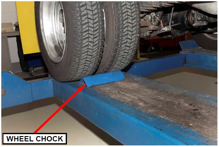
WARNING: If the vehicle is placed on a drive-on type hoist, apply the park brake and chock the rear wheels to prevent unintended vehicle movement (Figure 1).
NOTE: Ensure the vehicle is in neutral prior to lifting the vehicle to aid in propeller shaft removal/installation.
Figure 1 – Chock Rear Wheels
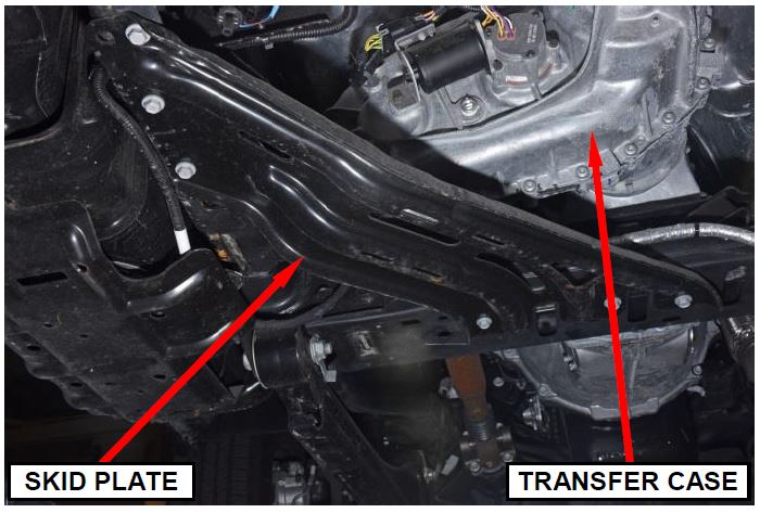
- Remove and save the transfer case skid plate (Figure 2).
Figure 2 – Transfer Case Skid Plate
- Drain the transfer case lubricant:
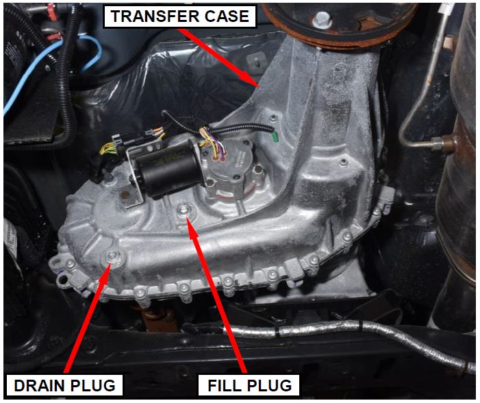
a. Position a drain pan under the transfer case (Figure 3).
b. Remove the drain plug and allow the lubricant to drain completely (Figure 3).
c. Install the drain plug. Tighten the drain plug to 15 – 22 ft. lbs. (19 – 30 N·m) (Figure 3).
d. Remove the drain pan.
Figure 3 – Lubricant Drain/Fill Plugs
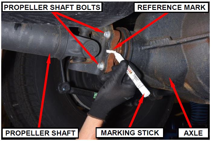
- Place alignment marks on the front and rear propeller shafts and the axle companion flanges for assembly alignment (Figure 4).
NOTE: Marking the transfer case companion flanges is not necessary because the transfer case is being replaced.
Figure 4 – Driveline Alignment Mark
- Remove and discard the companion flange-to-propeller shaft bolts from the front axle and transfer case.
- Remove and save the front propeller shaft.
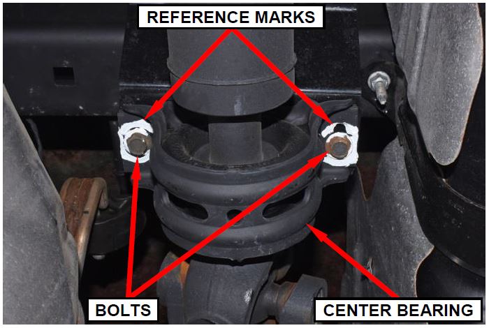
- Two and three piece rear propeller shafts only: Mark the position of the center bearing for installation reference. Support the propeller shaft then remove and discard the center bearing bolts (Figure 5).
Figure 5 – Rear Propeller Shaft Center Bearing Alignment Mark
NOTE: Two and three piece rear propeller shafts are difficult to handle and may require the help of an assistant for removal.
- Remove and discard the companion flange-to-propeller shaft bolts from the rear axle and transfer case.
- Remove and save the rear propeller shaft.
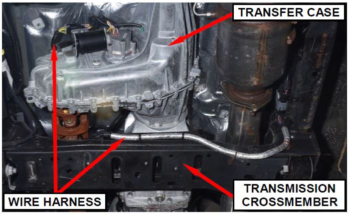
- Disconnect the transfer case electrical wire connectors and release the wire harness retainers from the transfer case (Figure 6).
- Release the electrical wire harness retainers from the transmission crossmember (Figure 6).
Figure 6 – Electrical Wire Harness
- Manual shift transfer case only: Disconnect the transfer case shift linkage from the transfer case.
- Disconnect the transfer case vent hose from the top of the transfer case.
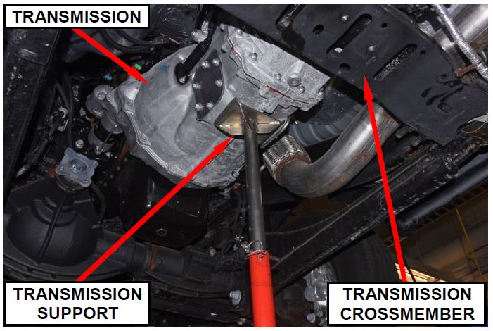
- Support the transmission with an appropriate transmission jack (Figure 7).
Figure 7 – Support Transmission
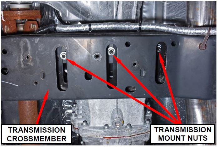
- Remove and save the transmission mount-to-transmission crossmember nuts (Figure 8).
Figure 8 – Transmission Mount Nuts
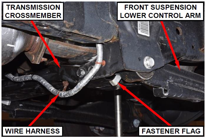
- For transmission crossmember removal clearance, the right side front suspension lower control arm fastener flag (Figure 9) must be positioned out of the way by following these steps:
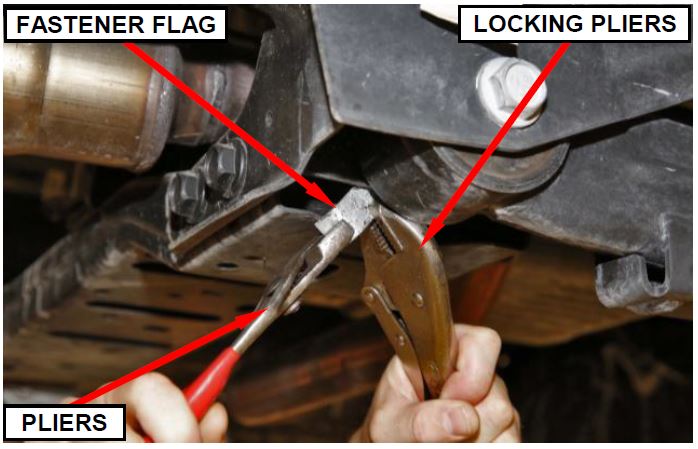
a. Use locking pliers to clamp the fastener flag in position relative to the vehicle frame to prevent fastener flag rotation while bending the flag (Figure 10).
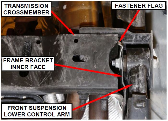
b. While the fastener flag is clamped to prevent rotation, use pliers to bend the flag end away from the crossmember until adequate clearance is achieved to allow for crossmember removal (Figures 10 and 11).
NOTE: Ensure that the fastener flag does not extend beyond the inner face of the frame bracket in order to prevent possible contact with the front suspension lower control arm (Figure 11).
c. Remove the locking pliers from the fastener flag once bending of the flag is complete.
Figure 9 – Fastener Flag Interference
Figure 10 – Bend Fastener Flag
Figure 11 – Fastener Flag Clearance
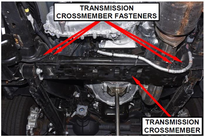
- Remove and save the four transmission crossmember-to-frame fasteners (Figure 12).
Figure 12 – Crossmember Fasteners
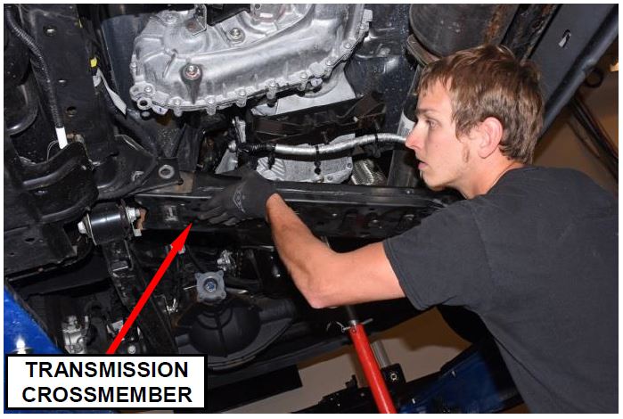
- Remove the transmission crossmember (Figure 13).
Figure 13 – Transmission Crossmember
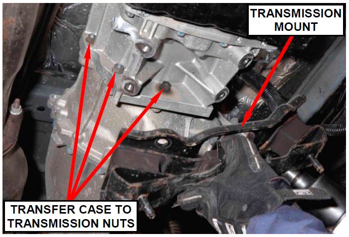
- Automatic transmission only: In order to access the transfer case lower fastening nut, remove and save the transmission mount-to-transmission bolts and mount (Figure 14).
Figure 14 – Transmission Mount
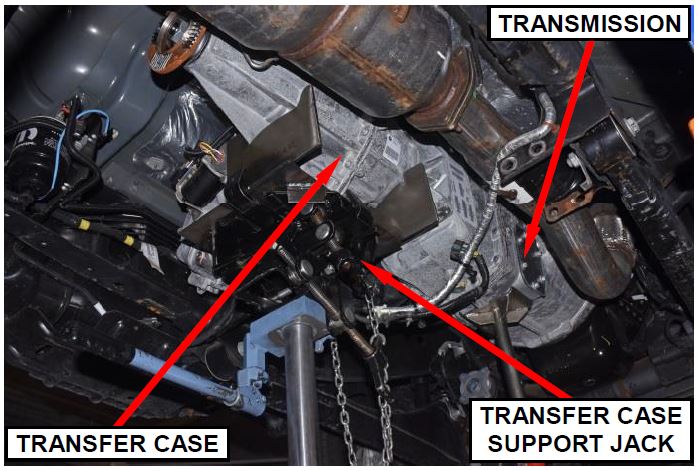
- Support the transfer case with a transmission jack and secure the transfer case to the transmission jack with straps or chains (Figure 15).
Figure 15 – Support Transfer Case
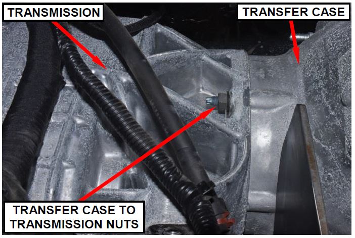
- Remove and discard the transfer case-to-transmission nuts (Figure 16).
Figure 16 – Transfer Case Fastening
- Pull the transfer case and jack rearward to disengage the transfer case from the transmission. Then remove the transfer case from under the vehicle.
- Remove the old transfer case from the jack. Then install the new transfer case onto the jack.
- Lift the transfer case into position and place the transfer case against the back of the transmission (Figure 15).
- Install the new transfer case-totransmission nuts. Tighten the nuts to 30 ft. lbs. (41 N·m) (Figure 16).
- Automatic transmission only: Install the transmission mount and mount-to-transmission bolts. Tighten the bolts to 45 ft. lbs. (61 N·m) (Figure 14).
- Install the transmission crossmember and the crossmember-to-frame fasteners. Tighten the fasteners to: (DD, DF models) 177 ft. lbs. (240 N·m) / (DP models) 94 ft. lbs. (127 N·m) (Figures 12 and 13).
- Lower the transmission onto the crossmember and install the transmission mountto-transmission crossmember nuts. Tighten the nuts to 40 ft. lbs. (54 N·m) (Figure 8).
- Connect the transfer case vent hose to the top of the transfer case.
- Connect the transfer case electrical connectors and secure the wire harness retainers to the transfercase (Figure 6).
- Secure the electrical wire harness retainers to the transmission crossmember (Figure 6).
- Manual shift transfer case only: Connect the transfer case shift linkage.
NOTE: Two and three piece rear drive shafts are difficult to handle and may require the help of an assistant for installation.
- Align the rear axle flange-to-propeller shaft reference marks made prior to removal. Install the rear propeller shaft using new bolts. Tighten the transfer case companion flange-to-propeller shaft bolts to 55 ft. lbs. (75 N·m). Tighten the axle flange-to-propeller shaft bolts to: (DD, DF models) 89 ft. lbs. (120 N·m) / (DP models) 55 ft. lbs. (75 N·m) (Figure 4).
- Two and three piece rear propeller shafts only: Align the propeller shaft center bearing bracket to the outline reference mark made prior to removal. Install new center bearing bolts. Tighten the bolts to 40 ft. lbs. (54 N·m) (Figure 5).
- Align the front axle flange-to-propeller shaft reference marks made prior to removal. Install the front propeller shaft using new bolts. Tighten the transfer case companion flange-to-propeller shaft bolts to 65 ft. lbs. (88 N·m). Tighten the axle flange-to-propeller shaft bolts to (DD, DF models) 85 ft. lbs. (115 N·m) / (DP models) 65 ft. lbs. (88 N·m).
- Fill the transfer case with lubricant:
a. Remove the fill plug (Figure 3).
b. Fill the transfer case with the correct fluid to the bottom edge of fill plug opening (Figure 3).
c. Install the fill plug. Tighten the plug to 15 – 22 ft. lbs. (19 – 30 N·m) (Figure 3).
d. Wipe away any excess fluid that may have spilled.
- Install the transfer case skid plate and bolts. Tighten the bolts to 27 ft. lbs. (37 N·m) (Figure 2).
- Lower the vehicle from the hoist.
- Connect the wiTECH scan tool and clear all Diagnostic Trouble Codes (DTCs).
- Disconnect the wiTECH scan tool from the vehicle.
- Road test the vehicle to verify repair.
- Return the vehicle to the customer.
Completion Reporting and Reimbursement
Claims for vehicles that have been serviced must be submitted on the DealerCONNECT Claim Entry Screen located on the Service tab. Claims submitted will be used by FCA to record recall service completions and provide dealer payments.
Use the following labor operation numbers and time allowances:
| Labor Operation Number | Time Allowance | |
|---|---|---|
| Replace Transfer Case Assembly | 21-S4-81-82 | 1.7 hours |
| Optional Equipment: | ||
| Transfer Case Skid Plate | 21- S4-81-60 | 0.1 hours |
| Two or Three Piece Rear Propeller Shaft | 21- S4-81-61 | 0.2 hours |
Add the cost of the recall parts package plus applicable dealer allowance to your claim.
NOTE: See the Warranty Administration Manual, Recall Claim Processing Section, for complete recall claim processing instructions.
Dealer Notification
To view this notification on DealerCONNECT, select “Global Recall System” on the Service tab, then click on the description of this notification.
Owner Notification and Service Scheduling
All involved vehicle owners known to FCA are being notified of the service requirement by first class mail. They are requested to schedule appointments for this service with their dealers. A generic copy of the owner letter is attached.
Enclosed with each owner letter is an Owner Notification postcard to allow owners to update our records if applicable.
Vehicle Lists, Global Recall System, VIP and Dealer Follow Up
All involved vehicles have been entered into the DealerCONNECT Global Recall System (GRS) and Vehicle Information Plus (VIP) for dealer inquiry as needed.
GRS provides involved dealers with an updated VIN list of their incomplete vehicles. The owner’s name, address and phone number are listed if known. Completed vehicles are removed from GRS within several days of repair claim submission.
To use this system, click on the “Service” tab and then click on “Global Recall System.” Your dealer’s VIN list for each recall displayed can be sorted by: those vehicles that were unsold at recall launch, those with a phone number, city, zip code, or VIN sequence.
Dealers must perform this repair on all unsold vehicles before retail delivery. Dealers should also use the VIN list to follow up with all owners to schedule appointments for this repair.
Recall VIN lists may contain confidential, restricted owner name and address information that was obtained from the Department of Motor Vehicles of various states. Use of this information is permitted for this recall only and is strictly prohibited from all other use.
Additional Information
If you have any questions or need assistance in completing this action, please contact your Service and Parts District Manager.
Customer Services / Field Operations
FCA US LLC
TRANSFER CASE REAR OUTPUT SHAFT
IMPORTANT SAFETY RECALL
S48 / NHTSA 16V-495
This notice applies to your vehicle (VIN: xxxxxxxxxxxxxxxxx).
This notice is sent to you in accordance with the National Traffic and Motor Vehicle Safety Act.
Dear: (Name)
FCA has decided that a defect, which relates to motor vehicle safety, exists in certain 2016 model year RAM Cab Chassis trucks equipped with four-wheel drive.
| The problem is… | The transfer case rear output shaft on your truck could fracture while driving. A fractured rear output shaft will result in a loss of motive power and a loss of “Park” functionality when the vehicle is operated in two-wheel drive mode. The loss of “Park” functionality could cause unintended vehicle movement. This could cause a crash and/or strike bystanders near the vehicle.
Also, 144.5” wheelbase trucks equipped with a one-piece rear propeller shaft may experience propeller shaft separation if the transfer case rear output shaft fractures. This could cause a crash without warning while driving. |
| What your dealer will do… | FCA will repair your vehicle free of charge. To do this, your dealer will replace the transfer case assembly on all involved vehicles. The work will take about 2½ hours to complete. However, additional time may be necessary depending on service schedules. |
| What you must do to ensure your safety… | Simply contact your Chrysler , Jeep , Jeep , Dodge , Dodge or RAM or RAM dealer right away to schedule a service appointment. Ask the dealer to hold the parts for your vehicle or to order them before your appointment. Please bring this letter with you to your dealer. dealer right away to schedule a service appointment. Ask the dealer to hold the parts for your vehicle or to order them before your appointment. Please bring this letter with you to your dealer. |
| If you need help… | If you have questions or concerns which your dealer is unable to resolve, please contact the FCA Group Recall Assistance Center at either fcarecalls.com or 1-800-853-1403. |
Please help us update our records by filling out the attached prepaid postcard if any of the conditions listed on the card apply to you or your vehicle. If you have further questions go to fcarecalls.com.
If you have already experienced this specific condition and have paid to have it repaired, you may visit www.fcarecallreimbursement.com to submit your reimbursement request online or you can mail your original receipts and proof of payment to the following address for reimbursement consideration: FCA Customer Assistance, P.O. Box 21-8004, Auburn Hills, MI 48321-8007, Attention: Recall Reimbursement. Once we receive and verify the required documents, reimbursement will be sent to you within 60 days. If you’ve had previous repairs and/or reimbursement you may still need to have the recall repair performed on your vehicle.
If your dealer fails or is unable to remedy this defect without charge and within a reasonable time, you may submit a written complaint to the Administrator, National Highway Traffic Safety Administration, 1200 New Jersey Ave., S.E., Washington, DC 20590, or you can call the toll-free Vehicle Safety Hotline at 1-888-327-4236 (TTY 1-800-424-9153), or go to safercar.gov.
We’re sorry for any inconvenience, but we are sincerely concerned about your safety. Thank you for your attention to this important matter.
Customer Services / Field Operations
FCA US LLC
Note to lessors receiving this recall: Federal regulation requires that you forward this recall notice to the lessee within 10 days.
 Loading...
 Loading...
