| “This site contains affiliate links for which OEMDTC may be compensated” |
NHTSA Campaign Number: 16V461
Component(s): POWER TRAIN
Potential Number of Units Affected: 26,299
Manufacturer: Chrysler (FCA US LLC)
SUMMARY:
Chrysler (FCA US LLC) is recalling certain model year 2015-2016 Chrysler Town & Country, Dodge Grand Caravan vehicles manufactured July 31, 2015, to April 18, 2016, 2016 Dodge Journey vehicles manufactured August 17, 2015, to January 29, 2016, and 2016 RAM ProMaster vehicles manufactured August 15, 2016, to April 15, 2016.
The transmission pump may seize causing a loss of hydraulic pressure.
CONSEQUENCE:
If the transmission loses hydraulic pressure, the vehicle may lose motive power, increasing the risk of a crash.
REMEDY:
Chrysler will notify owners, and dealers will replace the transmission pump, free of charge.
The recall began on August 18, 2016.
Owners may contact Chrysler customer service at 1-800-853-1403.
Chrysler’s number for this recall is S44.
NOTES:
Owners may also contact the National Highway Traffic Safety Administration Vehicle Safety Hotline at 1-888-327-4236 (TTY 1-800-424-9153), or go to www.safercar.gov.
Check if your Vehicle has a Recall
Revision 1 August 2016
Dealer Service Instructions for:
Safety Recall S44 / NHTSA 16V-461 Transaxle Oil Pump
NOTE: Figure 37 of the service procedure has been revised.
Models
| 2015 – 2016 | (RT) | Dodge Grand Caravan / Chrysler Town & Country |
NOTE: This recall applies only to the above vehicles equipped with a 3.6L engine (sales code ERB) and an automatic transaxle (sales code DG2) built from July 31, 2015 through April 18, 2016 (MDH 073106 through 041810).
| 2016 | (JC) | Dodge Journey |
NOTE: This recall applies only to the above vehicles equipped with a 3.6L engine (sales code ERB) and an automatic transaxle (sales code DG2) built from August 17, 2015 through January 29, 2016 (MDH 081720 through 012916).
| 2016 | (VF) | RAM ProMaster |
NOTE: This recall applies only to the above vehicles equipped with a 3.6L engine (sales code ERB) and an automatic transaxle (sales code DG2) built from August 12, 2015 through April 15, 2016 (MDH 081216 through 041511).
IMPORTANT: Some of the involved vehicles may be in dealer new vehicle inventory. Federal law requires you to complete this recall service on these vehicles before retail delivery. Dealers should also consider this requirement to apply to used vehicle inventory and should perform this recall on vehicles in for service. Involved vehicles can be determined by using the VIP inquiry process.
Subject
The transaxle oil pump on about 37,000 of the above vehicles may experience a loss of hydraulic oil pressure due to an improperly manufactured transaxle oil pump. A loss of transaxle hydraulic oil pressure while driving will result in a loss of motive power and could cause a crash without warning.
Repair
The transaxle oil pump must be replaced on all involved vehicles.
Parts Information
| Part Number | Description |
|---|---|
| CBDAS441AA | Oil Pump Package |
| Each package contains the following components: | |
| Quantity | Description |
| 1 | Pump, Oil |
| 1 | Seal, Torque Converter Oil |
| 1 | O-Ring, Oil Pump |
| 1 | Gasket, Oil Pump |
| 6 | Bolt/Washer, Pump Retaining |
| Each dealer to whom vehicles in the recall were assigned will receive enough Oil Pump Packages to service about 20% of those vehicles. | |
| RL070538AB | Converter, Torque (includes 4 torque converter bolts) (All models) |
| NOTE: The torque converter only needs to be replaced if the transaxle oil pump has failed and the vehicle was towed in with an inoperative transaxle due to oil pump failure. Order the above torque converter only when required. Do not order a torque converter for dealer inventory. Very few vehicles are expected to require a new torque converter. | |
| Part Number | Description |
| 06504383 |
Bolt, Torque Converter (4 required) (All models) |
| 06501916 | Push Pins, Inner Wheel Well (Minimum Sales Quantity (MSQ) 20 pins) |
| 06510124AA | Bolt, Halfshaft Support Bracket-to-Engine (3 required) (RT models) |
| 06104218AA |
Bolt, Halfshaft Support Bracket-to-Engine (3 Required) (JC & VF models) |
| 06509298AA |
Nut, Drive Hub to Halfshaft (2 required) (RT & JC models) |
| 06510636AA | Nut, Drive Hub to Halfshaft (2 Required) (VF models) |
| 68218057AB |
Oil, Automatic Transmission (MS – 9602) (All models) |
| 06511385AA | Bolts, Trans Mount (4 Required) (VF models) |
| 06105052AA |
Bolts, Cross under exhaust pipe (4 required) (RT & JC models) |
| 68102940AA | O-ring, Power Transfer Unit-to-Transaxle (JC AWD models) |
| 68093232AA |
Gasket, Cylinder Head-to-Catalytic Converter (JC AWD models) |
| 05085685AA |
Gasket, Cross-under Pipe (JC AWD models) |
SPECIAL NOTE: The shim/plates below are the most common shims required to set transaxle input shaft end play. Order the shim/plates below only when required. Do not order the shim/plates below for dealer inventory. Very few vehicles are expected to require the shim/plates listed below.
| Part Number | Description |
|---|---|
| 04431665AB | Shim/Plate 0.063 in. (1.60mm) |
| 03836237AB | Shim/Plate 0.068 in. (1.73mm) |
| 04431666AB | Shim/Plate 0.071 in. (1.80mm) |
| 03836238AB | Shim/Plate 0.077 in. (1.96mm) |
| 04431667AB | Shim/Plate 0.080 in. (2.03mm) |
| 03836239AB | Shim/Plate 0.085 in. (2.16mm) |
| 04431668AB | Shim/Plate 0.088 in. (2.24mm) |
Each dealer to whom vehicles in the recall were assigned will receive ONE (1) of each of the above shim/plates. Additional shim/plates may be ordered as required.
SPECIAL NOTE: The below shim/plates are low demand shim/plates that are not commonly needed. Order the below shim/plates only when required. Do not order these shim/plates for dealer inventory. Very few vehicles are expected to require any of the below shim/plates.
| Part Number | Description |
|---|---|
| 03836240AB | Shim/Plate 0.094 in. (2.39mm) |
| 04431669AB | Shim/Plate 0.097 in. (2.46mm) |
| 03836241AB | Shim/Plate 0.103 in. (2.62mm) |
| 04446670AB | Shim/Plate 0.105 in. (2.67mm) |
| 04446671AB | Shim/Plate 0.114 in. (2.90mm) |
Parts Return
Please make sure to retain this part until the recall claim is paid and the parts disposition has been determined. This recall part will be subject to parts return.
Special Tools
The following special tools are required to perform this repair:
|
wiTECH micro pod II |
|
Laptop Computer |
|
wiTECH Software |
|
Hammer, Slide |
|
End Play Set |
|
Oil Cooler Tube Disconnect Tool |
|
Installer, Oil Seal |
|
Dipstick, Transaxle Oil Level |
Service Procedure
A. Remove Transaxle (RT models)
- Place vehicle on an appropriate hoist.
- Open the hood.
- Remove and save the engine cover.
- Remove and save the battery.
- Remove and save the battery tray (Figure 1).
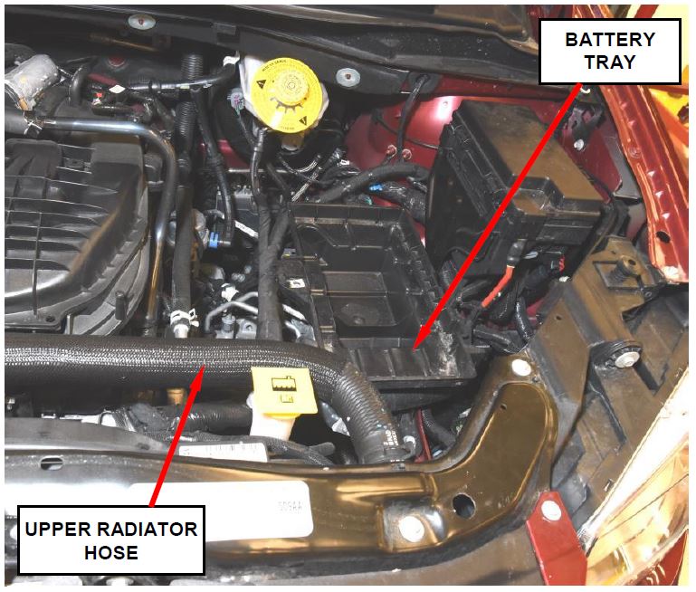 Figure 1 – Battery and Battery Tray
- Remove and save the brake booster vacuum pump (Figure 2).
- Remove and save brake booster vacuum pump mounting bracket (Figure 2).
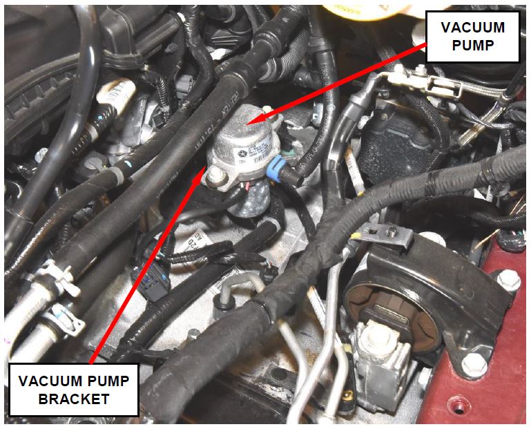 Figure 2 – Vacuum Pump and Bracket
- Using special tool 8875A, disconnect the transaxle cooler tubes from the transaxle (Figure 3).
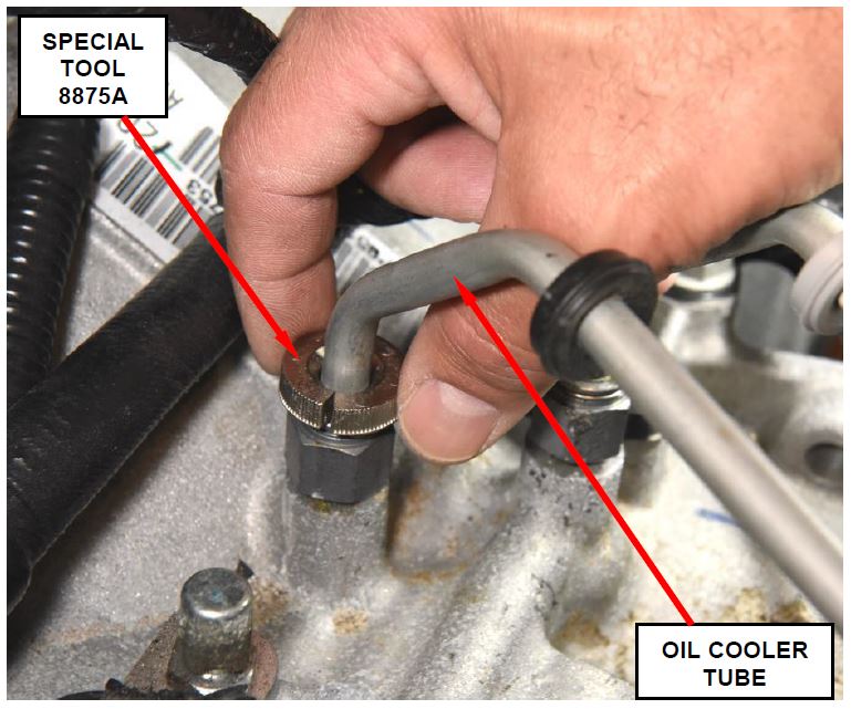 Figure 3 – Oil Cooler Tubes
- Disconnect the transaxle shift cable from the manual control lever (Figure 4).
- Disconnect the shift cable from the cable anchor bracket (Figure 4).
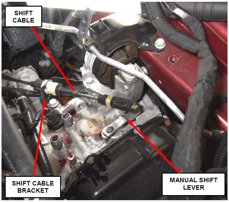 Figure 4 – Shift Cable
- Partially raise the vehicle on the hoist.
- Remove and save the front wheels.
- Raise vehicle completely.
- Disconnect the electrical connector for the engine crankshaft position sensor electrical connector.
- Disconnect the electrical connectors for both transaxle speed sensor located by the left halfshaft (Figure 5).
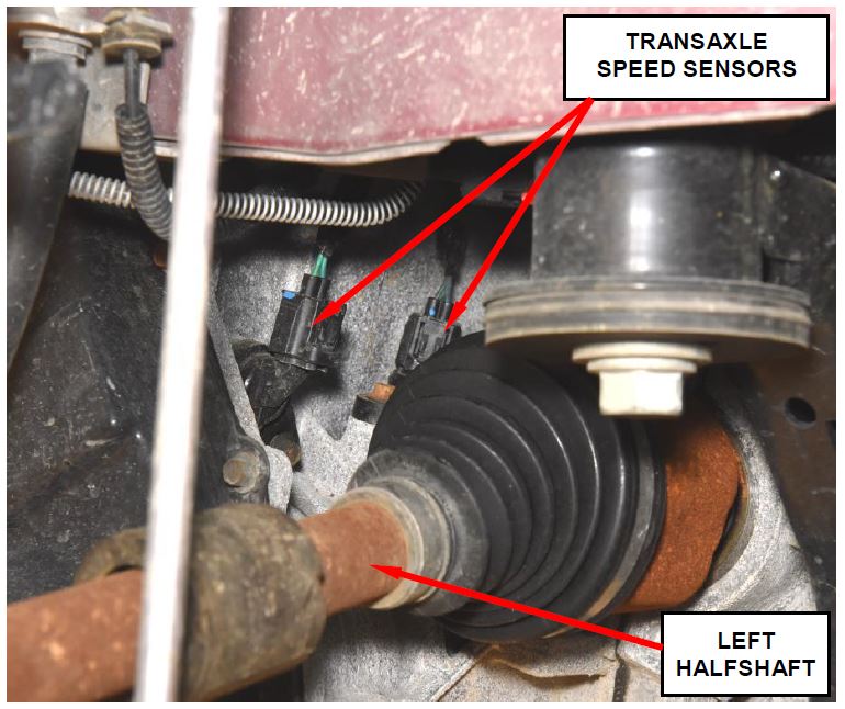 Figure 5 – Transaxle Speed Sensors
- Lower the vehicle from the hoist.
- Disconnect the round wire harness connector located at the front transaxle oil pan.
- Disconnect all remaining electrical connectors for the transaxle wire harness and set wire harness aside.
- Remove and save the upper transaxle bellhousing bolts and studs (Figure 6).
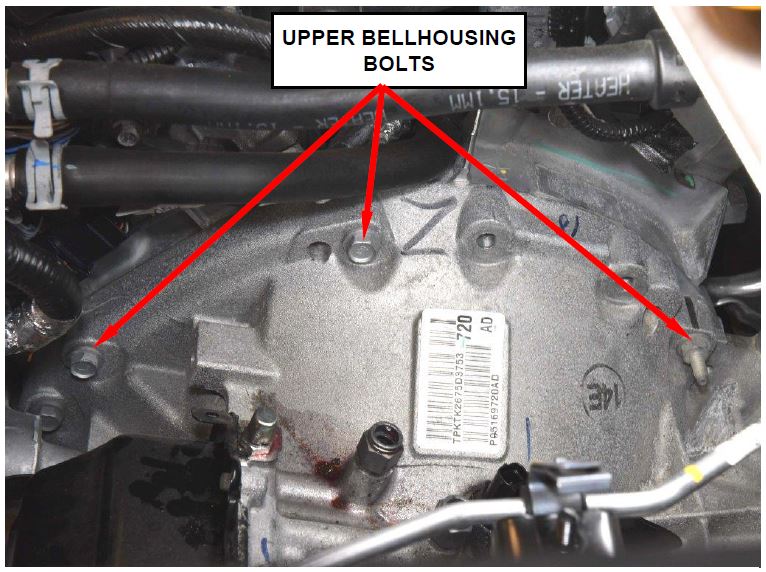 Figure 6 – Transaxle Bellhousing Bolts
- Raise the vehicle on the hoist.
- Remove and save the engine support crossmember.
- Remove and save the front engine mount bracket.
- Remove and save the two starter mounting bolts.
- Use the following procedure to remove halfshafts:
a. Remove and discard the right and left halfshaft retaining nuts (Figure 7).
b. Remove and relocate the front brake calipers and adapters as an assembly (Figure 7).
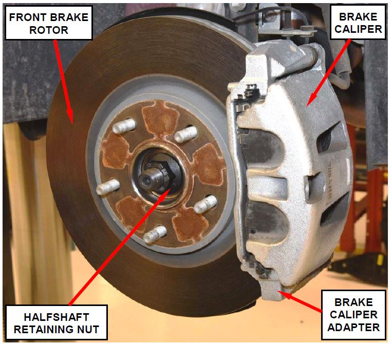 Figure 7 – Halfshaft Retaining Nut
CAUTION: Do not disconnect the flex hose from the brake caliper and do not allow the brake caliper to hang from the flex hose.
c. Remove and save the front brake rotors.
d. Remove and save the steering knuckle-to-strut bolts.
e. Pull the steering knuckle out of the strut bracket.
f. Disconnect wheel speed sensor routing grommet brackets from the strut bracket (Figure 8).
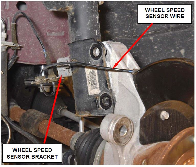 Figure 8 – Wheel Speed Sensor Wire
g. Separate the halfshaft from the wheel hub.
h. On the right halfshaft, unbolt the center support bearing bracket.
NOTE: The center support bearing bracket bolts are not reuseable. Discard the original bolts.
i. Using a pry bar, carefully pry against the inner tripod joint until the tripod joint retaining snap ring disengages.
j. Remove and save the right and left halfshafts.
- Remove and save the rear engine mount heat shield.
- Remove and save the rear engine mount through bolt.
- Lower the vehicle.
- Remove and save the rear engine mount bracket.
- Lift the vehicle on the hoist.
- Remove and save the torque converter drive plate access cover.
- Remove and discard the torque converter drive plate bolts.
- Place a transmission jack under the transaxle and secure the transaxle to the jack.
- Remove and save the remaining bellhousing bolts.
- Carefully remove the transaxle assembly from the vehicle.
- If the vehicle transaxle:
- is functional, continue with Section D. Replace Oil Pump.
- is completely inoperative (towed in), the transaxle torque converter must also be replaced. Continue with Section D. Replace Oil Pump.
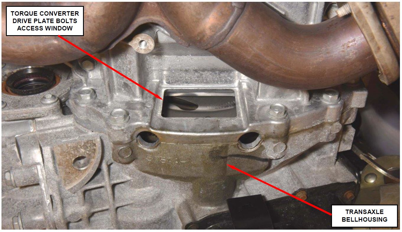 Figure 9 – Torque Converter Drive Plate Bolts
B. Remove Transaxle (JC models)
- Disconnect the negative battery cable.
- Remove and save the engine cover.
- Remove and save the air cleaner housing.
- Disconnect the gearshift cable from the transaxle manual valve lever (Figure 10).
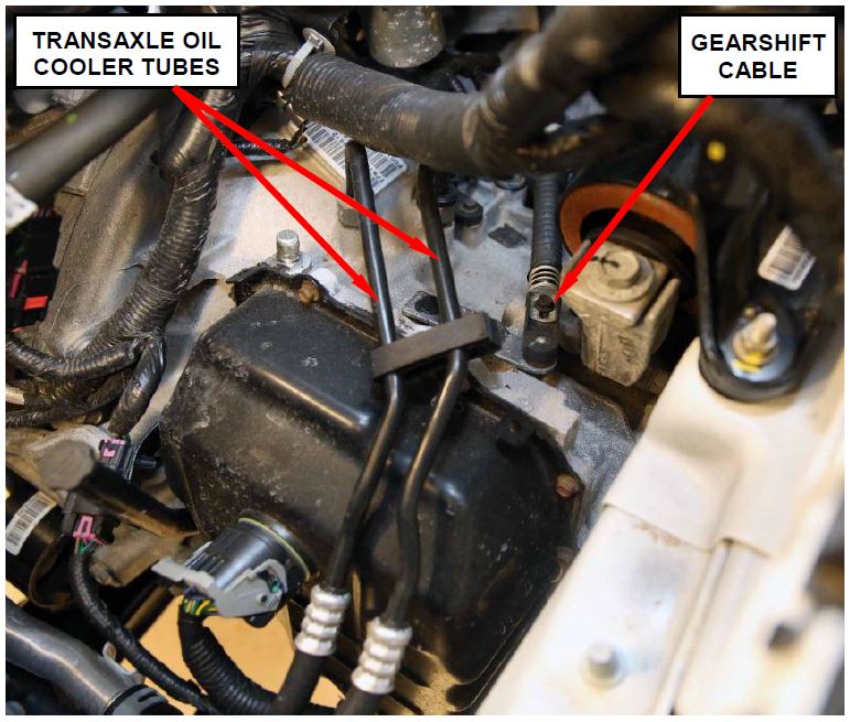 Figure 10 – Gear Shift Cable and Bracket
- Remove the gearshift cable from the bracket.
- Remove and save the vacuum pump.
- Remove and save the vacuum pump bracket.
- Disconnect transaxle related electrical connectors.
- Disconnect the crankshaft position sensor.
- Using special tool CY8875A, disconnect the transaxle oil cooler tubes at the transaxle (Figure 11).
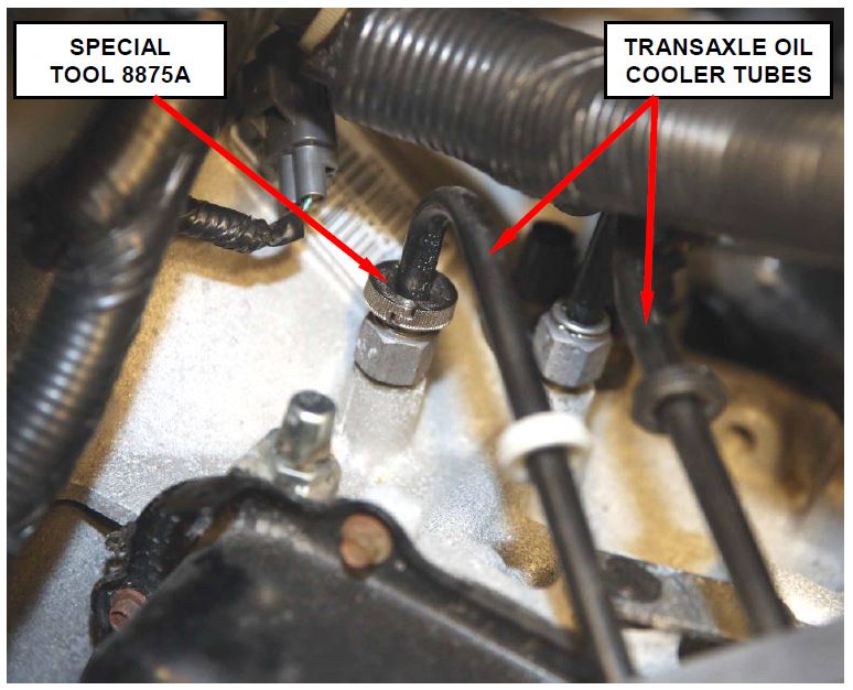 Figure 11 – Special Tool CY8875A
- Remove and save the remaining upper bellhousing bolts.
- Partially raise the vehicle on the hoist.
- Removed and save the front wheels.
- Use the following procedure to remove halfshafts:
a. Remove and discard the right and left halfshaft retaining nuts (Figure 12).
b. Remove and relocate the front brake calipers and adapters as an assembly (Figure 12).
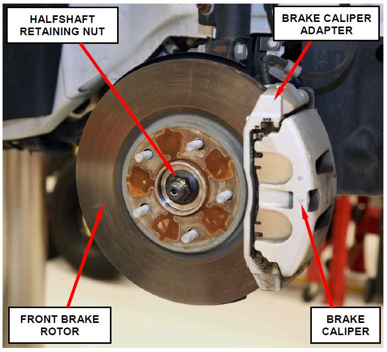 Figure 12 – Halfshaft Retaining Nut
CAUTION: Do not disconnect the flex hose from the brake caliper and do not allow the brake caliper to hang from the flex hose.
c. Remove and save the front brake rotors.
d. Remove and save the steering knuckle-to-strut bolts.
e. Pull the steering knuckle out of the strut bracket.
f. Disconnect wheel speed sensor routing grommet brackets from the strut bracket and frame rail.
g. Separate the halfshaft from the wheel hub.
h. On the right halfshaft, unbolt the center support bearing bracket.
NOTE: The center support bearing bracket bolts are not reuseable. Discard the original bolts.
i. Using a pry bar, carefully pry against the inner tripod joint until the tripod joint retaining snap ring disengages.
j. Remove and save the right and left halfshafts.
- Raise the vehicle on the hoist.
- Remove and save the fore/aft crossmember (Figure 13).
- For vehicles with All Wheel Drive, remove and save the exhaust cross-under pipe from the vehicle (Figure 13).
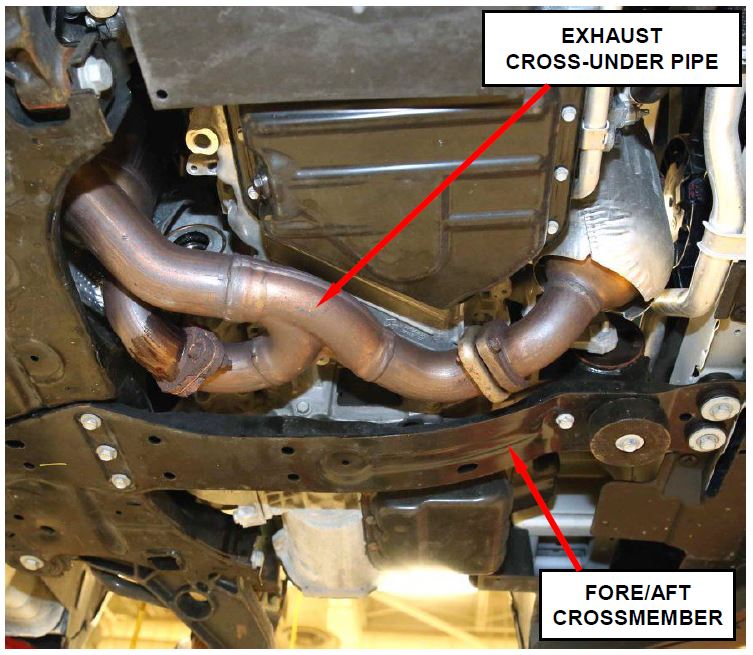 Figure 13 – Fore/Aft Crossmember and Cross-Under Exhaust Pipe
- For vehicles with All Wheel Drive, place an index mark on the propeller shaft flange to the rear axle flange.
- For vehicles with All Wheel Drive, remove and save the propeller shaft center bearing heat shield.
- For vehicles with All Wheel Drive, remove and save the rear propeller shaft assembly.
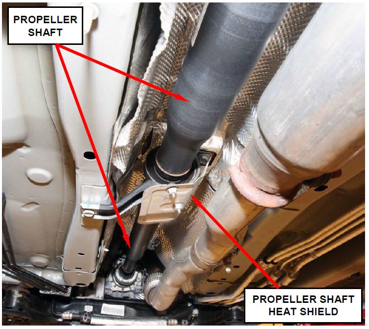 Figure 14 – Rear Propeller Shaft Heat Shield
- For vehicles with All Wheel Drive, remove and save rear catalytic converter (Figure 15).
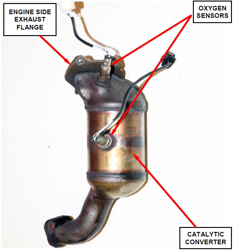 Figure 15 – Rear Catalytic Converter
- For vehicles with All Wheel Drive, remove and save the Power Transfer Unit (PTU) heat shield (Figure 16).
- Remove and save the right side engine splash shield.
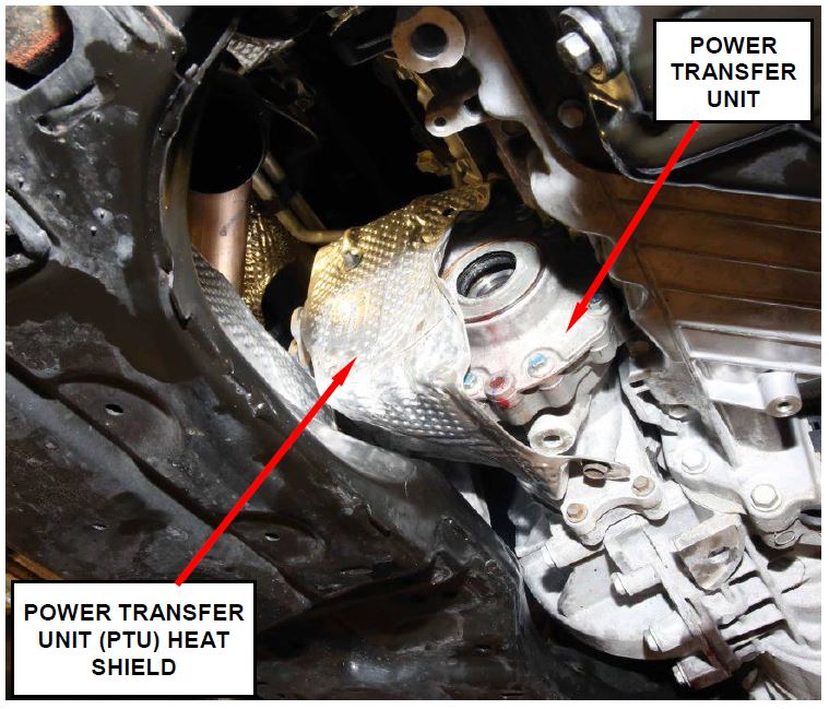 Figure 16 – PTU Heat Shield
- For vehicles with All Wheel Drive, pull the PTU off the transaxle and set aside without removing it from the vehicle.
NOTE: Allow the PTU to “nest” in the vehicle. Do not attempt to completely remove the PTU unit from the vehicle.
- Carefully disconnect the electrical connector on the speed sensor located at the back of the engine block.
- Remove and save the front engine mount/isolator bracket.
- Remove and save the two starter bolts.
- Remove and save the torque converter access panel (Figure 17).
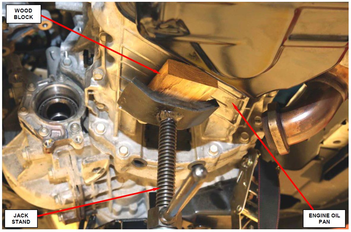 Figure 17 – Support Engine
- Remove and discard the torque converter drive plate bolts.
- Remove and save the rear engine mount/isolator bracket bolts. Do not remove the bracket or through-bolt.
- Support the engine with a small jack stand (Figure 17).
- Remove and save the transaxle mount and mount bracket.
- Lift the vehicle on the hoist.
- Place a transmission jack under the transaxle and secure the jack to the transaxle.
- Remove and save the lower bellhousing bolts (Figure 17).
- If the vehicle transaxle:
- is functional, continue with Section D. Replace Oil Pump.
- is completely inoperative (towed in), the transaxle torque converter must also be replaced. Continue with Section D. Replace Oil Pump.
C. Remove Transaxle (VF models)
- Remove and save the battery access panel located on the passenger compartment floor (Figure 18).
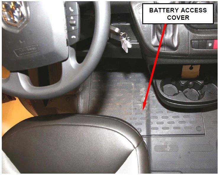 Figure 18 – Battery Access Panel
- Disconnect the negative battery cable.
- With the engine cold, open the blue cap on the coolant bottle to relieve any pressure in the coolant bottle.
CAUTION: Allow the engine to cool down before removing the coolant bottle cap. Never remove the cap on a hot engine.
- Disconnect the two small coolant hose on the top of the coolant bottle (Figure 19).
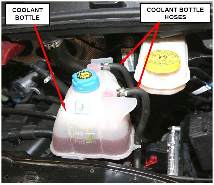 Figure 19 – Coolant Bottle Hoses
- Remove and save the coolant bottle fasteners.
- Using hose pinch-off pliers, pinch off the lower coolant hose at the coolant bottle (Figure 20).
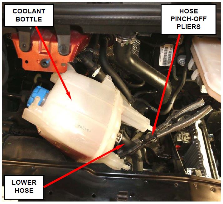 Figure 20 – Pinch-Off Lower Hose
- Disconnect the lower coolant hose at the coolant bottle.
- Remove and save the engine coolant bottle.
- Unbolt the Coolant bottle bracket and set aside.
- Disconnect the gear shift cable and disconnect from cable bracket.
- Disconnect the electrical connector for the speed sensor next to the oil cooler tubes.
- Using special tool CY8875A, disconnect both oil cooler tubes at the transaxle.
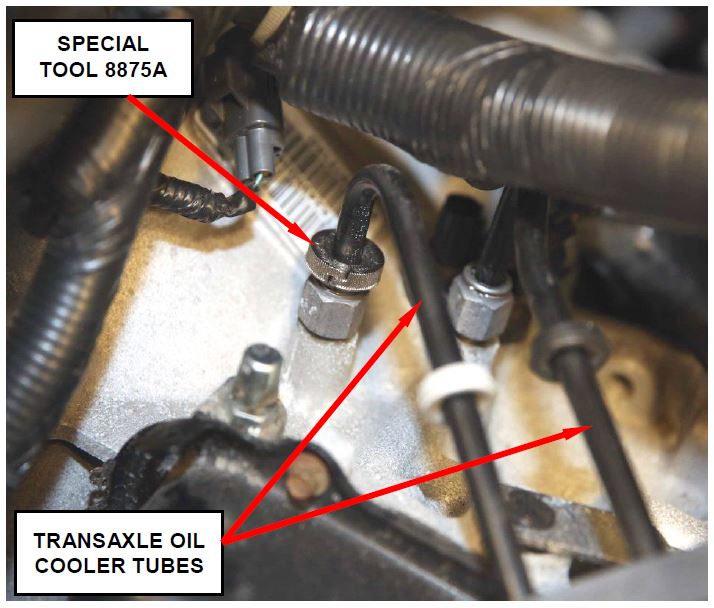 Figure 21- Transaxle Oil Cooler Tubes
- Remove and save the vertical transaxle mount bracket bolt.
- Remove and save the upper bellhousing bolts.
- Partially lift the vehicle on the hoist.
- Remove and save the front wheels.
- Unstake the two stakes on the right and left halfshaft retaining nuts (Figure 22).
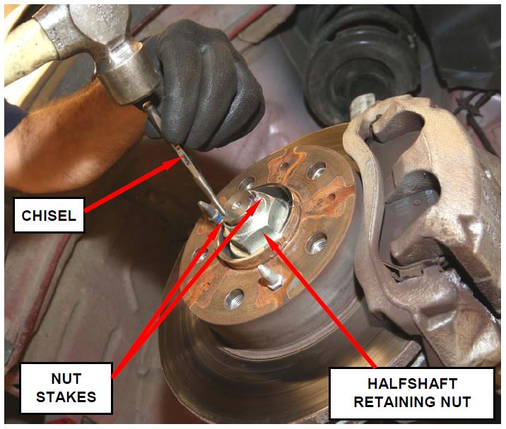 Figure 22 – Unstake Halfshaft Retaining Nut
- Remove and discard the right and left halfshaft nuts.
- Remove and save the right and left side stabilizer bar link nuts at the lower control arm.
- Disconnect the brake hose from the strut tube bracket (Figure 23).
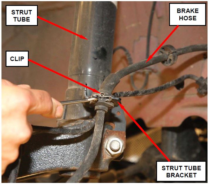 Figure 23 – Brake Hose Clip
- Remove and save the three ball joint retaining bolts at the steering knuckle (Figure 24).
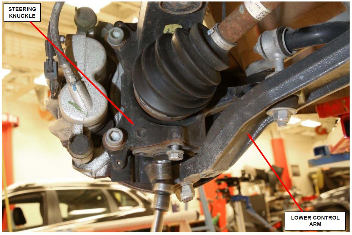 Figure 24 – Three Ball Joint Retaining Bolts
- For the left halfshaft, pull the steering knuckle away from the vehicle while disengaging the halfshaft from the wheel hub and remove the halfshaft (Figure 25).
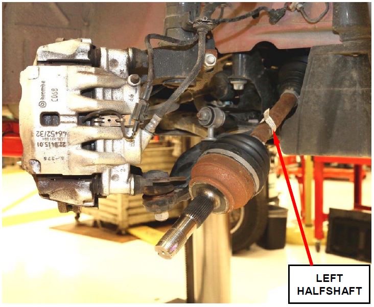 Figure 25 – Left Halfshaft
- Remove and save the engine splash shield.
- For the right halfshaft:
a. Remove and save the three bolts for the halfshaft bearing support bracket (Figure 26).
b. Pull the steering knuckle away from the vehicle while disengaging the halfshaft from the wheel hub.
c. Remove the halfshaft and extension shaft as an assembly.
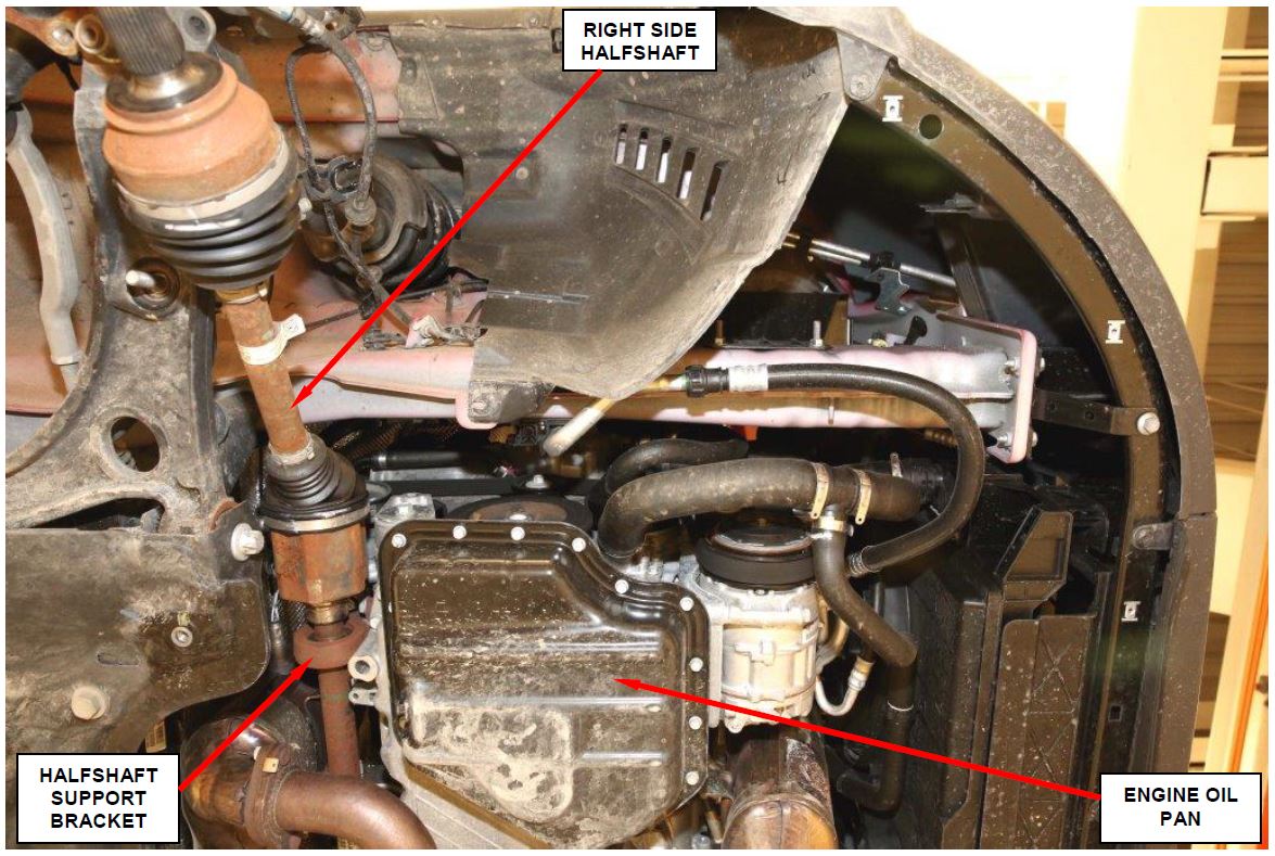 Figure 26 – Right Halfshaft
- Disconnect the crankshaft position sensor electrical connector.
- Lower the vehicle.
- Disconnect all transaxle related electrical connections and set the wire harness aside.
- Disconnect the oil cooler tube guide bracket from the transaxle (Figure 27).
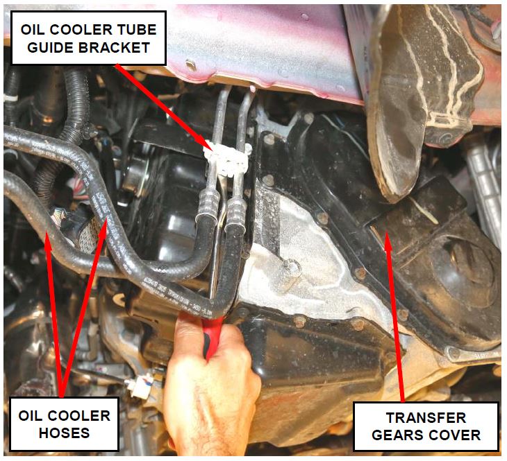 Figure 27 – Oil Cooler Tube Guide Bracket
- Remove and save the starter wire guide bracket retaining bolt.
- Remove and save the two starter bolts.
- Remove and save the rear engine mount through-bolt (Figure 28).
- Remove and save the rear engine mount-to-suspension cradle bolt (Figure 28).
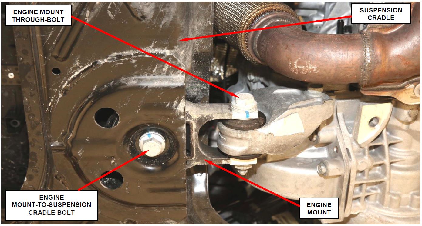 Figure 28 – Rear Engine Mount
- Roll the engine forward and remove the rear engine mount.
- Remove and save the drive plate bolt access cover.
- Remove and discard the four drive plate bolts.
- Support the engine with a jack stand (Figure 29).
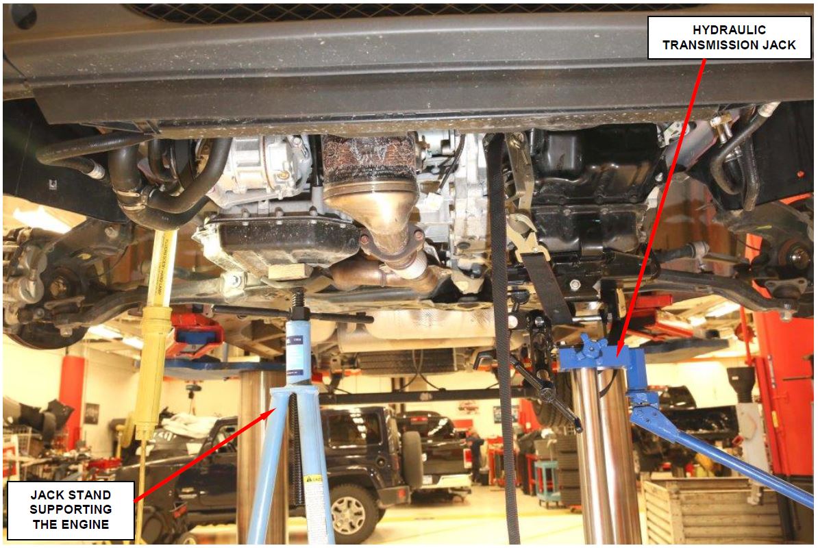 Figure 29 – Support Engine and Transaxle
WARNING: The engine must be supported with a jack stand (Figure 29). The right engine mount will come apart and the engine may fall out of the vehicle if the engine is not supported. Personal injury could result from an unsupported engine.
- Place a transmission jack under the transaxle and secure the transaxle to the transmission jack (Figure 29).
- Remove and save the four transaxle mount retaining bolts.
- Lower the transaxle slightly and remove the transaxle ground strap (Figure 30).
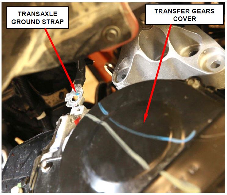 Figure 30 – Transaxle Ground Strap
- Remove the lower bellhousing bolts.
- Carefully lower the transaxle from the vehicle (Figure 31).
 Figure 31 – Lower Transaxle from Vehicle
- If the vehicle transaxle:
- is functional, continue with Section D. Replace Oil Pump.
- is completely inoperative (towed in), the transaxle torque converter must also be replaced. Continue with Section D. Replace Oil Pump.
D. Replace Transaxle Oil Pump
- Place the transaxle on a bench.
- Remove the torque converter (Figure 32).
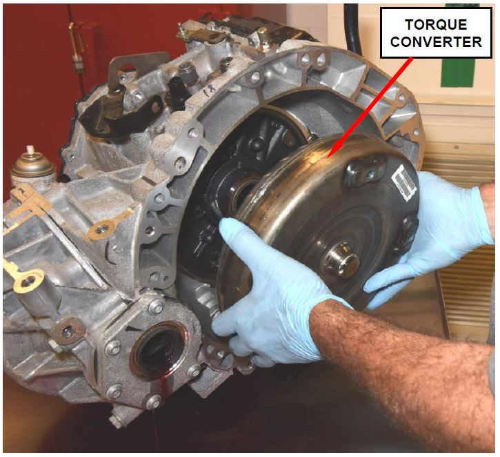 Figure 32 – Torque Converter
- Position the transaxle so that the bellhousing is facing upward.
- Install special tool 8266-7 and 8266-8 onto the transaxle input shaft.
- Install a dial indicator as shown in Figure 33.
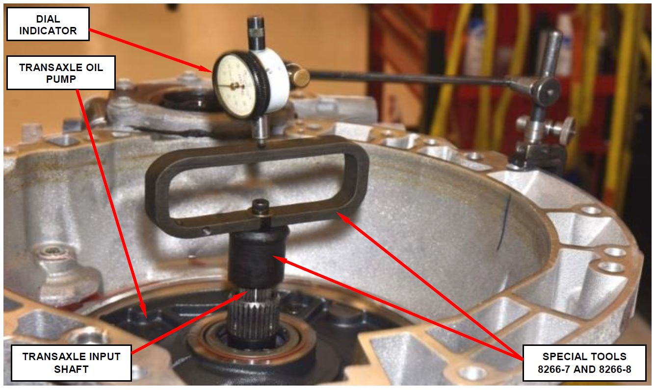 Figure 33 – Measure Input Shaft End Play
NOTE: The transaxle input shaft end play should be 0.005 in. to 0.025 in. (0.13 to 0.64 mm).
- Use the following procedure to measure input shaft end play:
a. Push down on special tool handle (8266-8) to seat the input shaft (Figure 33).
b. Zero the dial indicator (Figure 33).
c. Pull upward on the special tool handle (8266-8) and read the dial indicator (Figure 33).
d. Record the end play measurement for future reference.
- Remove the dial indicator and special tools 8266-7/8266-8 from the transaxle.
- Remove and save the six oil pump retaining bolts.
- Install the oil pump slide hammers (special tool 3752A).
- Using the slide hammers, remove and discard the original transaxle oil pump (Figure 34).
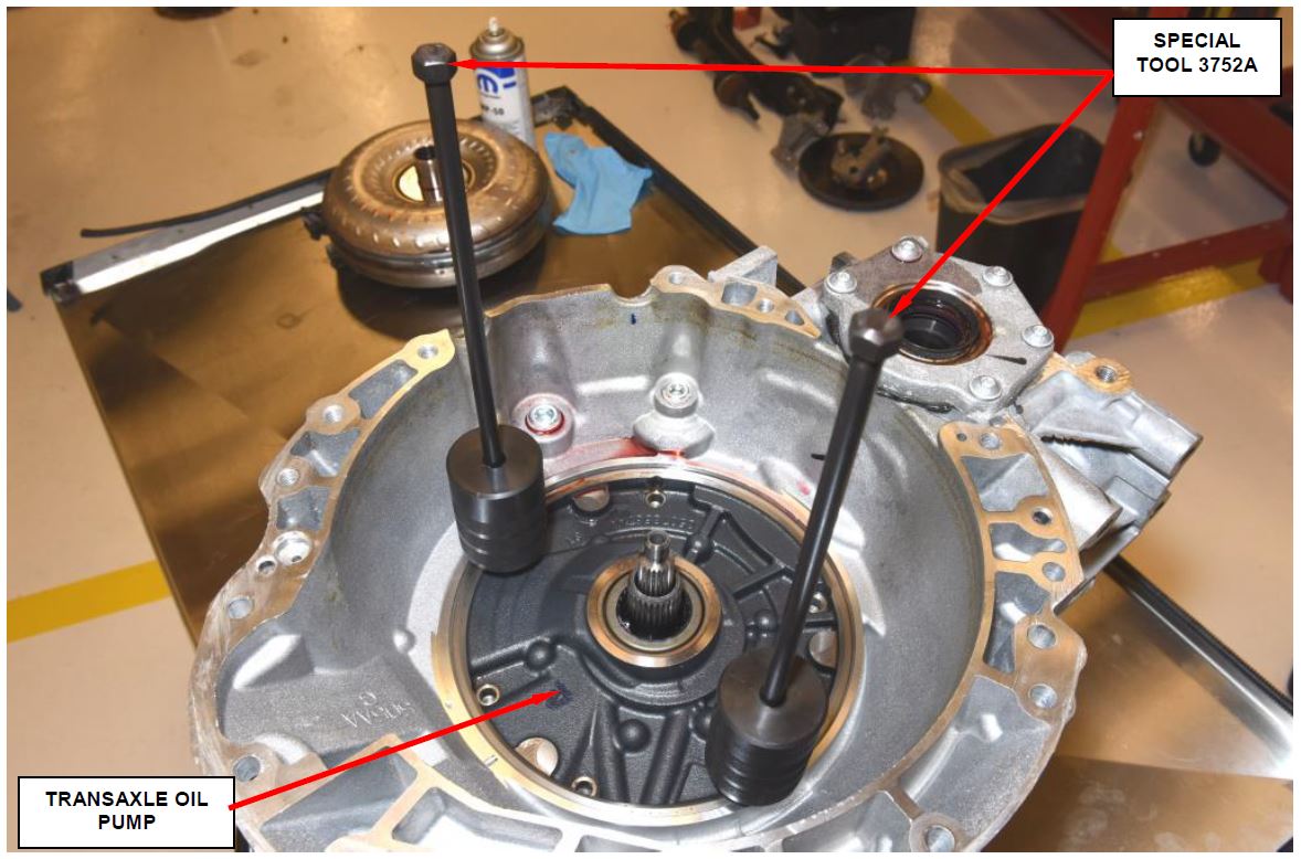 Figure 34 – Oil Pump Slide Hammers
- Perform the following steps on the new oil pump:
a. Using special tool C-4193A, install the torque converter oil seal (Figure 35).
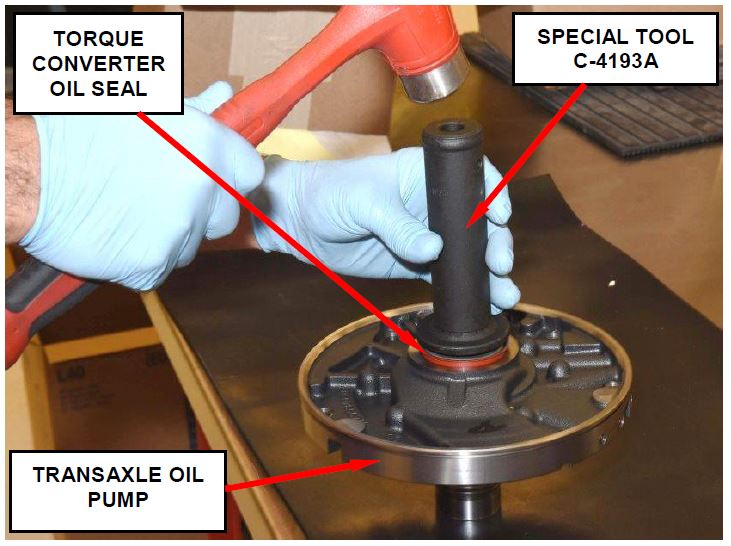 Figure 35 – Oil Seal Installation
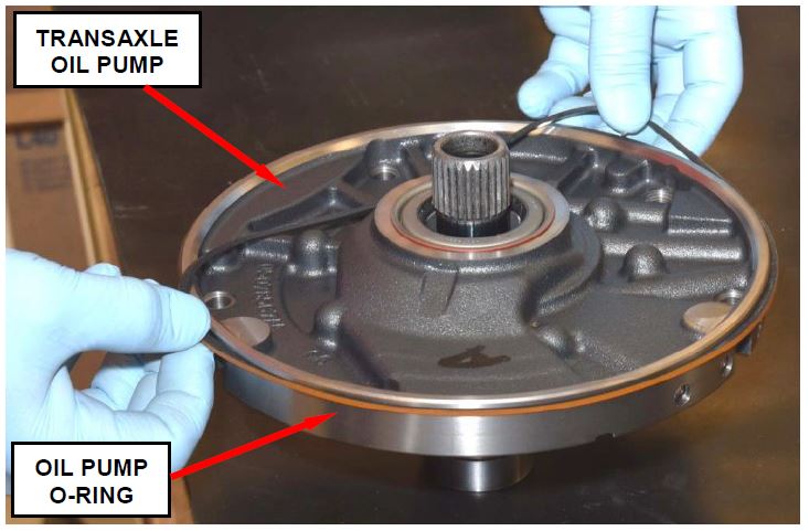
b. Install a new oil pump o-ring onto the new oil pump (Figure 36).
c. Install four oil pump seal rings onto the new oil pump (Figure 37).
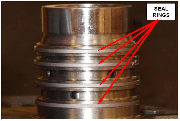 Figure 37 – Oil Pump Seal Rings
- Install the oil pump into the transaxle.
- Install the six original oil pump retaining bolts.
- Tighten the oil pump bolts evenly to draw the pump down into the transaxle case.
- Once the oil pump is seated, tighten oil pump bolts to 22 ft. lbs. (30 N·m).
- Install special tool 8266-7 and 8266-8 onto the transaxle input shaft.
- Install a dial indicator as shown in Figure 33 and measure input shaft end play.
NOTE: The transaxle input shaft end play should be 0.005 to 0.025 in. (0.13 to 0.64 mm).
- If the input shaft end play:
- is within specifications, continue with Step 19 of this procedure.
- is not within specifications, continue with Step 21 of this procedure.
- Remove the original oil pump bolts one at a time and replace them with new oil pump bolts. Tighten the new oil pump bolts to 22 ft. lbs. (30 N·m).
- Continue with:
- Section E. Install Transaxle (RT Models)
- Section F. Install Transaxle (JC Models)
- Section G. Install Transaxle (VF Models)
- If the input shaft end play is out of specification, perform the following steps:
a. Remove the input speed sensor.
b. Remove and save the six oil pump retaining bolts.
c. Install the oil pump slide hammers (special tool 3752A).
d. Using the slide hammers, remove the new transaxle oil pump.
e. Lift the input clutch assembly out of the transaxle case.
f. Remove the original No. 4 thrust plate.
g. Apply petrolium jelly or transmission assembly grease to the No. 4 Thrust plate.
h. Determine and install the correct thickness No. 4 thrust plate.
NOTE: A thinner No. 4 thrust plate will increase input shaft end play. A thicker No. 4 thrust plate will decrease input shaft end play.
i. With the No. 4 thrust plate in position, install the input clutch assembly.
j. Verify that the new oil pump gasket is in position.
k. Install the new oil pump assembly. Tighten the new oil pump bolts to 22 ft. lbs. (30 N·m).
l. Install the input speed sensor.
- Install a dial indicator as shown in Figure 33 and verify input shaft end play.
NOTE: The transaxle input shaft end play should be 0.005 to 0.025 in. (0.13 to 0.64 mm).
- Continue with:
- Section E. Install Transaxle (RT Models)
- Section F. Install Transaxle (JC Models)
- Section G. Install Transaxle (VF Models)
E. Install Transaxle (RT Models)
- Place the transaxle onto the transmission jack and secure.
- Install the torque converter.
CAUTION: If the transaxle pump failed (vehicle towed in), install a new torque converter assembly.
- While pushing torque converter inward, rotate the torque converter until the torque converter is fully seated in the oil pump gears.
- Using the transmission jack, lift the transaxle into place.
- Install lower bell housing bolts. Tighten the bolts to 52 ft. lbs. (70 N·m).
- Install new torque converter drive bolts. Tighten the bolts to 44 ft. lbs. (60 N·m).
- Install torque converter drive bolt plastic access cover.
- Install right side engine splash shield.
- With the engine supported, lower the vehicle.
- Install the transaxle mount bracket.
- Install the transaxle mount. Tighten the bolts to 74 ft. lbs. (100 N·m).
- Install the rear engine mount bracket. Tighten the bolts to 81 ft. lbs. (110 N·m).
- Raise the vehicle on the hoist.
- Install the rear engine mount through bolt. Tighten the bolt to 45 ft. (61 N·m).
- Install the rear engine mount heat shield.
- Install the right side halfshaft into position. Tighten the new halfshaft center support bearing bracket retaining bolts to 39 ft. lbs. (54 N·m).
CAUTION: Do not reuse the original halfshaft center support bearing bracket retaining bolts.
- Install a new right side halfshaft nut. Tighten the new nut to 118 ft. lbs. (160 N·m).
- Push the steering knuckle into the strut bracket.
- Install the steering knuckle-to-strut bolts. Tighten the bolt to 65 ft. (88 N·m) plus an additional 90° turn after torque is met.
- Install the right side brake rotor and brake caliper. Tighten the brake caliper adapter bolts to 150 ft. lbs. (203 N·m).
- Route wheel speed sensor wiring and secure.
- Install the left halfshaft. Tighten the new halfshaft retaining nut to 118 ft. lbs. (160 N·m).
- Install the left side brake rotor and brake caliper. Tighten the brake caliper adapter bolts to 150 ft. lbs. (203 N·m).
- Install the starter motor retaining bolts. Tighten the bolts to 41 ft. lbs. (55 N·m).
- Install front motor mount bracket. Tighten the bolts to 41 ft. lbs. (55 N·m).
- Install front fore/aft crossmember as an assemby. Tighten the forward mounting bolt to 83 ft. lbs. (113 N·m). Tighten the rearward mounting bolts at the suspension crossmember to 41 ft. lbs. (55 N·m).
- Install front engine mount thru-bolt. Tighten bolt to 42 ft. lbs. (57 N·m).
- Lower the vehicle.
- Install the upper bellhousing bolts. Tighten the bolts to 52 ft. lbs. (70 N·m).
- Place wiring harness into position and make all electrical connections.
- Lift the vehicle on the hoist.
- Connect the crankshaft position sensor electrical connector.
- Partially lower the vehicle.
- Install the front wheels. Progressively tighten all wheel mounting nuts in the proper sequence. Tighten nuts to a final torque of 100 ft. lbs. (135 N·m).
- Lower the vehicle.
- Install the shift cable.
- Install transaxle oil cooler tubes.
- Install the vacuum pump bracket. Tighten the bolts to 52 ft. lbs. (70 N·m).
- Install vacuum pump onto the vacuum pump bracket.
- Route the power steering tube into position.
- Install the battery tray.
- Install the battery.
- Install the air cleaner assembly.
- Pump the brake pedal several times to seat the disc brake pads against the brake rotors.
- Apply the “Park” brake to prevent unintended vehicle movement.
- Start engine and check for leaks. Repair as required.
- Start engine and allow the transaxle to reach operating temperature.
- Continue with Section H. Check Transaxle Fluid Level (All Models)
F. Install Transaxle (JC Models)
- Place the transaxle onto the transmission jack and secure.
- Install the torque converter.
CAUTION: If the transaxle pump failed (vehicle towed in), install a new torque converter assembly.
- While pushing torque converter inward, rotate the torque converter until the torque converter is fully seated in the oil pump gears.
- Using the transmission jack, lift the transaxle into place.
- Install lower bell housing bolts. Tighten the bolts to 52 ft. lbs. (70 N·m).
- Install new torque converter drive bolts. Tighten the bolts to 44 ft. lbs. (60 N·m).
- Install torque converter drive bolt plastic access cover.
- Support the engine and transaxle with the engine support fixture.
- Remove transmission jack.
- Lower the vehicle.
- Install the transaxle mount aluminum bracket to the transaxle case. Tighten the four bolts to
- Align transaxle mount to the bracket on the transaxle and install the two mounting bolts. Tighten the bolts to 74 ft.lbs. (100 N·m).
- Align rear mount and install mounting bolts. Tighten the bolts to 81 ft. lbs. (110 N·m).
- Lift vehicle on the hoist.
- Install the two starter bolts. Tighten the bolts to 41 ft. lbs. (55 N·m).
- Install front motor mount bracket. Tighten the bolts to 41 ft. lbs. (55 N·m).
- Connect the engine speed sensor electrical connector.
- For vehicles with All Wheel Drive, remove and discard the original PTU-to-transaxle O-ring.
- For vehicles with All Wheel Drive, clean the O-ring groove.
- For vehicles with All Wheel Drive, install the new O-ring in the groove on the PTU.
- For vehicles with All Wheel Drive, place the PTU into position and install the four mounting bolts. Tighten the lower mounting bolts to 16 ft. lbs. (22 N·m).
- For vehicles with All Wheel Drive, install the PTU heat shield. Tighten the lower heat shield bolt to 16 ft. lbs. (22 N·m).
- For vehicles with All Wheel Drive, tighten the upper PTU mounting bolts to 40 ft. lbs. (54 N·m).
- For vehicles with All Wheel Drive, replace the cylinder head-to-catalytic converter gasket. Tighten lower gasket retainer bolts 27 ft. lbs. (37 N·m).
- For vehicles with All Wheel Drive, clean the catalytic converter flange.
- For vehicles with All Wheel Drive, place rear catalytic converter into position. Tighten the two upper retaining bolts to 27 ft. lbs. (37 N·m).
- For vehicles with All Wheel Drive, clean the exhaust cross-under pipe flanges.
- For vehicles with All Wheel Drive, install the exhaust cross-under pipe. Tighten the front flange mounting bolts to 21 ft. lbs. (28 N·m). Tighten the rear flange mounting bolts to 22 ft. lbs. (30 N·m). Tighten the muffler/resonator pipe clamp to 40 ft. lbs. (55 N·m).
- For vehicles with All Wheel Drive, install the rear propeller shaft assembly. Tighten the Propeller Shaft-to-Driveline Module mounting bolts to 40 ft. lbs. (54 N·m). Tighten the Propeller Shaft-to-PTU mounting bolts to 22 ft. lbs. (30 N·m).
- Install front fore/aft crossmember as an assemby. Tighten the forward mounting bolt to 83 ft. lbs. (113 N·m). Tighten the rearward mounting bolts at the suspension crossmember to 41 ft. lbs. (55 N·m).
- Install the front engine mount thru-bolt. Tighten the bolt to 44 ft. lbs. (60 N·m).
- Install the right side halfshaft into position. Tighten the new halfshaft center support bearing bracket retaining bolts to 28 ft. lbs. (38 N·m).
CAUTION: Do not reuse the original halfshaft center support bearing bracket retaining bolts.
- Install the new right side halfshaft nut. Tighten the nut to 118 ft. lbs. (160 N·m).
- Push the steering knuckle into the strut bracket.
- Install the steering knuckle-to-strut bolts. Tighten the bolt to 65 ft. (88 N·m) plus an additional 90° turn after torque is met.
- Install the right side brake rotor and brake caliper. Tighten the brake caliper adapter bolts to 150 ft. lbs. (203 N·m).
- Route right side wheel speed sensor wiring and secure.
- Install the left halfshaft. Tighten the new halfshaft retaining nut to 118 ft. lbs. (160 N·m).
- Install the left side brake rotor and brake caliper. Tighten the brake caliper adapter bolts to 150 ft. lbs. (203 N·m).
- Route left side wheel speed sensor wiring and secure.
- Install right side engine splash shield.
- Install front wheels. Tighten the lug nuts to 100 ft. lbs. (135 N·m).
- Install the upper bellhousing bolts. Tighten the bolts to 52 ft. lbs. (70 N·m).
- Install transaxle oil cooler tubes.
- Place wiring harness into position and make all electrical connections.
- Install the vacuum pump bracket. Tighten the bolts to 52 ft. lbs. (70 N·m).
- Install vacuum pump onto the vacuum pump bracket.
- Install the shift cable.
- Install the air cleaner assembly.
- Pump the brake pedal several times to seat the disc brake pads against the brake rotors.
- Apply the “Park” brake to prevent unintended vehicle movement.
- Start engine and check for transaxle fluid leaks. Repair as required.
- Start engine and allow the transaxle to reach operating temperature.
- Continue with Section H. Check Transaxle Fluid Level (All Models).
G. Install Transaxle (VF Models)
- Place the transaxle onto the transmission jack and secure.
- Install the torque converter.
CAUTION: If the transaxle pump failed (vehicle towed in), install a new torque converter assembly.
- While pushing torque converter inward, rotate the torque converter until the torque converter is fully seated in the oil pump gears.
- Using the transmission jack, lift the transaxle into place.
- Install lower bell housing bolts. Tighten the bolts to 52 ft. lbs. (70 N·m).
- Install the new torque converter drive bolts. Tighten the bolts to 44 ft. lbs. (60 N·m).
- Install torque converter drive bolt plastic access cover.
- Connect the transaxle ground strap.
- Raise the transaxle into position and install four new transaxle mount bolts. Tighten the bolts to 77 ft. lbs. (105 N·m).
- Install rear engine mount. Tighten the rear engine mount through-bolt and suspension cradle bolts to 214 ft. lbs. (290 N·m).
- Install the starter bolts. Tighten the bolts to 41 ft. lbs. (55 N·m).
- Install the starter wire guide bracket retaining bolt.
- Install the oil cooler tube guide bracket.
- Connect all transaxle related electrical connections.
- Install left halfshaft.
- Place the ball joint into position on the steering knuckle and install the three retaining bolts (Figure 24). Tighten the three bolts to 96 ft. lbs. (130 N·m).
- Connect the brake hose to the strut tube bracket.
- Connect the crankshaft position sensor electrical connector.
- Install the right side halfshaft. Tighten the halfshaft support bracket bolts to 25 lbs. (34 N·m) (Figure 26).
- Place the ball joint into position on the steering knuckle and install the three retaining bolts (Figure 24). Tighten the three bolts to 96 ft. lbs. (130 N·m).
- Connect the brake hose to the strut tube bracket.
- Install the left and right side stabilizer bar link nuts at the lower control arm.
- Partially lower the vehicle from the hoist.
- Install new right and left side halfshaft retaining nuts. Tighten the new nuts to 350 lbs. (475 N·m).
- Place two stakes on each halfshaft retaining nut.
- Install the engine splash shield.
- Install the front wheels. Tighten the lug bolts to 133 lbs. (180 N·m).
- Lower the vehicle from the hoist.
- Install the upper bellhousing bolts.
- Install the vertical transaxle mount bolt.
- Connect the transaxle oil cooler tubes.
- Connect the electrical connector for the speed sensor located next to the oil cooler tubes.
- Connect the gear shift cable to the shift arm and cable bracket.
- Install the coolant bottle bracket.
- Place the coolant bottle in position and connect the lower coolant hose.
- Remove the pinch-off pliers from the lower coolant hose.
- Place the coolant bottle into position and install the coolant bottle fasteners.
- Connect the two small hoses to the top of the coolant bottle.
- Connect the negative battery cable.
- Install the battery access cover.
- Pump the brake pedal several times to seat the disc brake pads against the brake rotors.
- Apply the “Park” brake to prevent unintended vehicle movement.
- Start engine and check for transaxle fluid leaks. Repair as required.
- Start engine and allow the transaxle to reach operating temperature.
- Continue with Section H. Check Transaxle Fluid Level (All Models).
H. Check Transaxle Fluid Level (All Models)
- Connect the wiTECH scan tool to the vehicle and start a session.
- Verify that the vehicle is parked on a level surface and the park brake is applied.
- Remove and save the dipstick tube cap
WARNING: There is a risk of accident from vehicle moving when the engine is running. Secure vehicle to prevent it from moving. There is a risk of injury from contusions and burns if you insert your hands into the engine when it is running. Do not touch hot or rotating parts. Wear properly fitted work clothes
- Start engine and let it run at idle speed in selector lever position “P”.
- Shift through the transmission modes several times with the vehicle stationary and the engine idling.
- Warm up the transmission, wait at least 2 minutes and check the oil level with the engine running. Push the Oil Dipstick 9336A into transmission fill tube until the dipstick tip contacts the oil pan and pull out again, read off oil level, repeat if necessary.
CAUTION: When inserting dipstick special tool 9336A, excess insertion force may cause the dipstick to slip past the stop on the bracket in the transmission oil pan. An approximate distance that the dipstick should be inserted into the fill tube is 16.69 in. (424 mm).
- Check transmission oil temperature using the appropriate scan tool.
- The transmission Oil Dipstick 9336A has indicator marks every 10 mm. Determine the height of the oil level on the dipstick and using the height, the Transmission Fluid Temperature (TFT) as viewed with the scan too, and the Transmission Fluid Graph, determine if the transmission oil level is correct (Figure 38).
- Add or remove oil as necessary and recheck the oil level.
- Once the oil level is correct, install the dipstick tube cap.
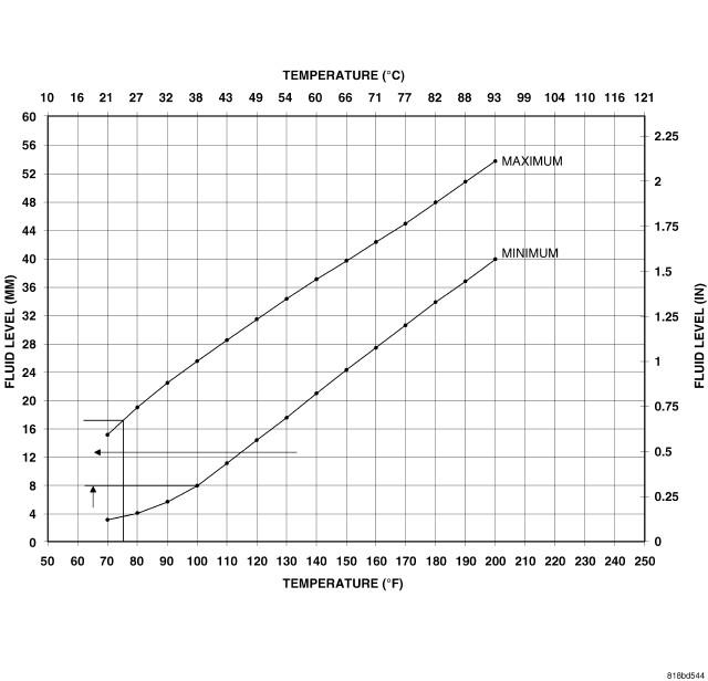 Figure 38 – Fluid Temperature/Level Chartf
- Clear all Diagnostic Trouble Codes (DTC’s).
- Remove the wiTECH scan tool from the vehicle.
- Install the engine cover.
- Close the hood.
- Road test the vehicle to confirm the repair.
- Return the vehicle to the customer.
Completion Reporting and Reimbursement
Claims for vehicles that have been serviced must be submitted on the DealerCONNECT Claim Entry Screen located on the Service tab. Claims submitted will be used by FCA to record recall service completions and provide dealer payments.
Use the following labor operation numbers and time allowances:
| Labor Operation Number | Time Allowance | |
|---|---|---|
| Replace transaxle oil pump | ||
| RT Models | 21-S4-41-82 | 5.1 hours |
| JC Models | 21-S4-41-83 | 4.6 hours |
| VF Models | 21-S4-41-84 | 4.6 hours |
| Related Operation | ||
| Remove oil pump a second time to install the correct thickness No. 4 thrust plate | 21-S4-41-50 | 0.5 hours |
| Replace torque converter | 21-S4-41-51 | 0.1 hours |
| Optional Equipment | ||
| JC vehicles with All Wheel Drive (AWD) | 21-S4-41-60 | 1.4 hours |
Add the cost of the recall parts package plus applicable dealer allowance to your claim.
NOTE: See the Warranty Administration Manual, Recall Claim Processing Section, for complete recall claim processing instructions.
Dealer Notification
To view this notification on DealerCONNECT, select “Global Recall System” on the Service tab, then click on the description of this notification.
Owner Notification and Service Scheduling
All involved vehicle owners known to FCA are being notified of the service requirement by first class mail. They are requested to schedule appointments for this service with their dealers. A generic copy of the owner letter is attached.
Enclosed with each owner letter is an Owner Notification postcard to allow owners to update our records if applicable.
Vehicle Lists, Global Recall System, VIP and Dealer Follow Up
All involved vehicles have been entered into the DealerCONNECT Global Recall System (GRS) and Vehicle Information Plus (VIP) for dealer inquiry as needed.
GRS provides involved dealers with an updated VIN list of their incomplete vehicles. The owner’s name, address and phone number are listed if known. Completed vehicles are removed from GRS within several days of repair claim submission.
To use this system, click on the “Service” tab and then click on “Global Recall System.” Your dealer’s VIN list for each recall displayed can be sorted by: those vehicles that were unsold at recall launch, those with a phone number, city, zip code, or VIN sequence.
Dealers must perform this repair on all unsold vehicles before retail delivery. Dealers should also use the VIN list to follow up with all owners to schedule appointments for this repair.
Recall VIN lists may contain confidential, restricted owner name and address information that was obtained from the Department of Motor Vehicles of various states. Use of this information is permitted for this recall only and is strictly prohibited from all other use.
Additional Information
If you have any questions or need assistance in completing this action, please contact your Service and Parts District Manager.
Customer Services / Field Operations
FCA US LLC
TRANSAXLE OIL PUMP
IMPORTANT SAFETY RECALL
S44 / NHTSA 16V-461
This notice applies to your vehicle (VIN: xxxxxxxxxxxxxxxxx).
This notice is sent to you in accordance with the National Traffic and Motor Vehicle Safety Act. Dear: (Name)
FCA has decided that a defect, which relates to motor vehicle safety, exists in certain 2015 and 2016 model year Dodge Grand Caravan, Chrysler Town & Country, Dodge Journey and RAM ProMaster vehicles.
| The problem is… | The transaxle oil pump in your vehicle may experience a loss of hydraulic oil pressure due to an improperly manufactured transaxle oil pump. A loss of transaxle hydraulic oil pressure while driving will result in a loss of motive power and could cause a crash without warning. |
| What your dealer will do… | FCA will repair your vehicle free of charge. To do this, your dealer will replace the transaxle oil pump. The work will take about seven hours to complete. However, additional time may be necessary depending on service schedules. |
| What you must do to ensure your safety… | Simply contact your Chrysler, Jeep, Dodge or RAM dealer right away to schedule a service appointment. Ask the dealer to hold the parts for your vehicle or to order them before your appointment. Please bring this letter with you to your dealer. |
| If you need help… | If you have questions or concerns which your dealer is unable to resolve, please contact the FCA Group Recall Assistance Center at either fcarecalls.com or 1-800-853-1403. |
Please help us update our records by filling out the attached prepaid postcard if any of the conditions listed on the card apply to you or your vehicle. If you have further questions go to fcarecalls.com.
If you have already experienced this specific condition and have paid to have it repaired, you may visit www.fcarecallreimbursement.com to submit your reimbursement request online or you can mail your original receipts and proof of payment to the following address for reimbursement consideration: FCA Customer Assistance, P.O. Box 21-8004, Auburn Hills, MI 48321-8007, Attention: Recall Reimbursement. Once we receive and verify the required documents, reimbursement will be sent to you within 60 days. If you’ve had previous repairs and/or reimbursement you may still need to have the recall repair performed on your vehicle.
If your dealer fails or is unable to remedy this defect without charge and within a reasonable time, you may submit a written complaint to the Administrator, National Highway Traffic Safety Administration, 1200 New Jersey Ave., S.E., Washington, DC 20590, or you can call the toll-free Vehicle Safety Hotline at 1-888-327-4236 (TTY 1-800-424-9153), or go to safercar.gov.
We’re sorry for any inconvenience, but we are sincerely concerned about your safety. Thank you for your attention to this important matter.
Customer Services / Field Operations
FCA US LLC
Note to lessors receiving this recall: Federal regulation requires that you forward this recall notice to the lessee within 10 days.
 Loading...


As technology is advancing more and more, ignorance is growing exponentially. And we, the peoples will suffer this mistakes.