| “This site contains affiliate links for which OEMDTC may be compensated” |
NHTSA Campaign Number: 16V736
Manufacturer Chrysler (FCA US LLC)
Components AIR BAGS
Potential Number of Units Affected 14
Improper Driver Air Bag Wire Routing
If the driver’s air bag wires are pinched, the air bag may not deploy properly in the event of a crash necessitating air bag deployment, increasing the risk of injury.
Summary
Chrysler (FCA US LLC) is recalling certain model year 2016 Dodge
 Viper vehicles manufactured May 24, 2016, to August 28, 2016.
The wires for the driver’s frontal air bag may be pinched.
Remedy
Dodge will notify owners, and dealers will replace the driver’s frontal air bag and clockspring, free of charge.
The recall began on November 17, 2016.
Owners may contact Chrysler customer service at 1-800-853-1403.
Chrysler ’s recall number for this recall is S75.
Notes
Owners may also contact the National Highway Traffic Safety Administration Vehicle Safety Hotline at 1-888-327-4236 (TTY 1-800-424-9153), or go to www.safercar.gov.
Check if your Vehicle has a Recall
November 2016
Dealer Service Instructions for:
Safety Recall S75 / NHTSA 16V-736 Driver Airbag Connectors
Models
| 2016 | (ZD) | Dodge Viper Viper |
NOTE: This recall applies only to the above vehicles from June 03, 2016 through June 27, 2016 (MDH 060311 through 062710).
| IMPORTANT: Some of the involved vehicles may be in dealer used vehicle inventory. Dealers should complete this recall service on these vehicles before retail delivery. Dealers should also perform this recall on vehicles in for service. Involved vehicles can be determined by using the VIP inquiry process. |
Subject
The Driver Airbag (DAB) inflator connectors on about 18 of the above vehicles may have been misaligned during component assembly. The misaligned DAB connectors result in a misrouting of the DAB airbag wiring harness. This misrouting of the DAB wiring harness may cause the DAB wires to become pinched or damaged. A pinched or damaged DAB wiring harness may cause the DAB system to malfunction and not deploy the DAB during a crash event. If the DAB system malfunctions, the Airbag Warning Light (ABWL) will illuminate. A malfunctioning DAB system could increase the risk of injury or death to the vehicle driver during a crash.
Repair
The DAB and the steering column airbag clockspring must be replaced.
Parts Information
| Part Number | Description |
|---|---|
| 6JU47DX9AA | Airbag, Driver Black DAB Cover w/ gunmetal trim ring and chrome/black viper logo (Non ACR vehicles without Premium Laguna Interior Package) |
| 6JU48DX9AA | Airbag, Driver Black DAB Cover w/ piano black trim ring and black/header red viper logo (All ACR vehicles) |
| 68110739AD | Clockspring |
| 06507532AA | Screw, Hex Flange Head (Steering Wheel) |
Each dealer with vehicle(s) in the recall assigned will need to email the VIN requiring 6JU47DX9AA or 6JU48DX9AA to campaignteam@fcagroup.com due to the very small vehicle population. Once the VIN is verified parts will be ordered on your behalf. Only about 18 vehicles are expected to require 6JU47DX9AA or 6JU48DX9AA.
Parts Return
No parts return required for this campaign.
Special Tools
No special tools are required to perform this service procedure.
Service Procedure
A. Replace Driver Airbag (DAB) and Clockspring
WARNING: To avoid serious or fatal injury on vehicles equipped with airbags, disable the Supplemental Restraint System (SRS) before attempting any steering wheel, steering column, airbag, Occupant Classification System (OCS), seat belt tensioner, impact sensor or instrument panel component diagnosis or service. Disconnect and isolate the battery negative (ground) cable, then wait two minutes for the system capacitor to discharge before performing further diagnosis or service. This is the only sure way to disable the SRS. Failure to follow these instructions may result in accidental airbag deployment.
NOTE: The following procedure is for replacement of an ineffective or damaged Driver AirBag (DAB). If the airbag is ineffective or damaged, but not deployed, review the recommended procedures for Handling NonDeployed Supplemental Restraints.
- Disconnect and isolate the negative battery cable. If equipped with an Intelligent Battery Sensor (IBS), disconnect the IBS connector first before disconnecting the negative battery cable. Wait two minutes for the system capacitor to discharge before further service.
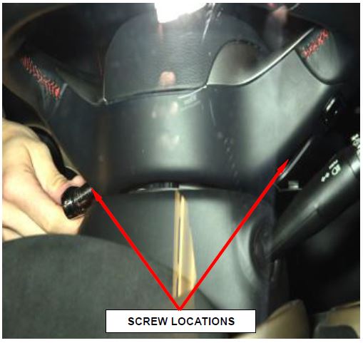
- Unsnap and move aside the screw covers from the access holes on the back of each horizontal spoke of the rear trim cover on the steering wheel.
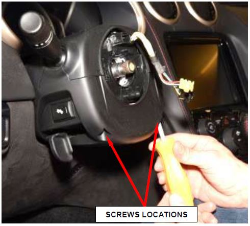
- Working through the access holes in each side of the steering wheel rear trim cover, remove and save the two screws that secure the DAB to the steering wheel armature (Figure 1).
Figure 1 – Driver Airbag Screws
- Pull the DAB away from the steering wheel far enough to access the electrical connections at the back of the airbag housing.
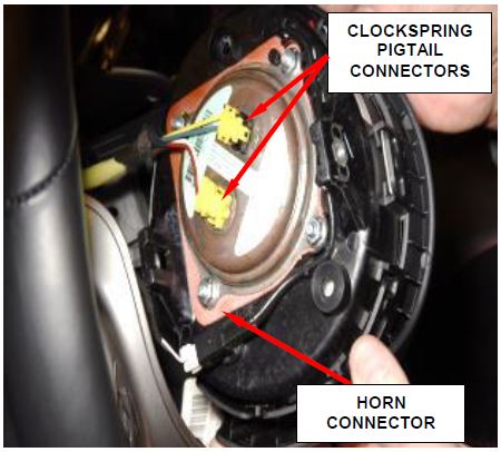
- Disconnect the steering wheel wire harness connector from the horn switch connector (4) on the back of the airbag housing (Figure 2).
CAUTION: Do not pull on the clockspring pigtail wires or pry on the connector insulators to disengage them from the Driver AirBag (DAB) inflator initiator connector receptacles. Improper removal of these pigtail wires and their connector insulators can result in damage to the airbag circuits or the connector insulators.
Figure 2 – Electrical Connectors
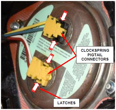
- The clockspring DAB pigtail wire connector insulators are secured by integral latches to the airbag inflator connector receptacles, which are located on the back of the airbag housing. Pinch both latches firmly, then pull the insulators straight out from the airbag inflator to disconnect them from the connector receptacles (Figures 2 and 3).
Figure 3 – Clockspring Connectors
- Remove and discard the DAB from the steering wheel. Dispose of all non-deployed airbags in a manner consistent with state, provincial, local and federal regulations. Refer to the Hazardous Substance Control System for proper disposal.
CAUTION: Always turn the steering wheel until the front wheels are in the straight-ahead position. Then, prior to removing the clockspring from the steering column or disconnecting the steering column from the steering gear, lock the steering wheel to the steering column or securely fasten the clockspring rotor to the clockspring case. If clockspring centering has been compromised for ANY reason, the entire clockspring and Steering Angle Sensor (SAS) unit MUST be replaced with a new unit.
- Place the front wheels in the straight ahead position.
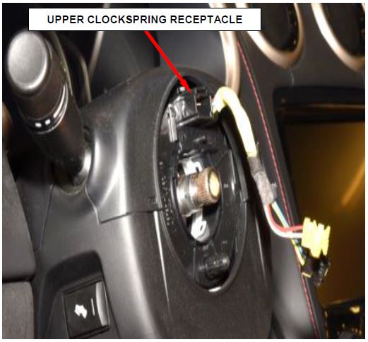
- Disconnect the steering wheel wire harness connector from the upper clockspring connector receptacle (Figure 4).
- While holding the steering wheel firmly in place, remove and steering wheel retaining bolt from steering column shaft in center of steering wheel.
Figure 4 – Upper Clockspring Receptacle
NOTE: Threading the retaining bolt back in the end of the shaft until approximately 0.5 in. (13 mm) of thread is showing between the wheel and the head of the bolt allows a safe reaction surface when the steering wheel is removed.
- Thread wheel retaining bolt back into end of steering shaft until approximately 0.5 in. (13 mm) of thread is showing between wheel and head of bolt.
CAUTION: Do not bump or hammer on the steering wheel or steering column shaft when removing the steering wheel.
- Grasp the steering wheel firmly and pull rearward to remove steering wheel from steering column shaft. Remove and discard the steering wheel retaining bolt.
- Use the following steps to remove the upper and lower shrouds from the steering column.
a. Remove two screws attaching lower shroud to steering column and upper After removing screws, unclip the shrouds from one another by applying hand pressure along seams where shrouds connect, then remove lower shroud from upper shroud and column (Figure 5).
b. Remove upper shroud from steering column.
Figure 5 – Steering Column Shrouds
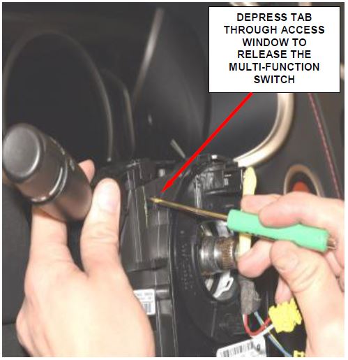
- Working through the access window of the mounting bracket integral to the left side of the clockspring, depress the tab of the latch feature integral to the multifunction switch housing far enough to disengage the latch (Figure 6).
Figure 6 – Multifunction Switch Removal
- While holding the latch disengaged, slide the switch upward and out of the receptacle in the mounting bracket.
- Disconnect the multi-function switch electrical connector then remove and save the multi-function switch.
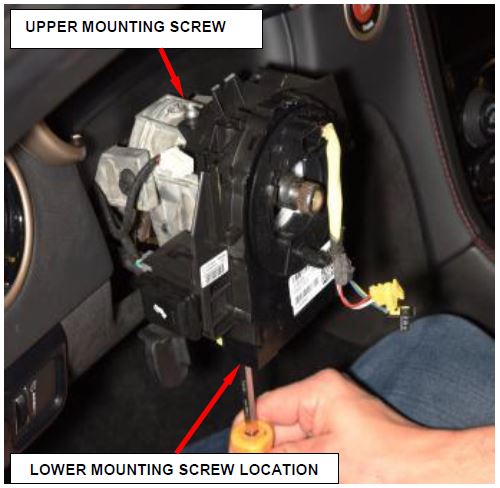
- Remove the two clockspring mounting screws (Figure 7)
Figure 7 – Clockspring Mounting Screws
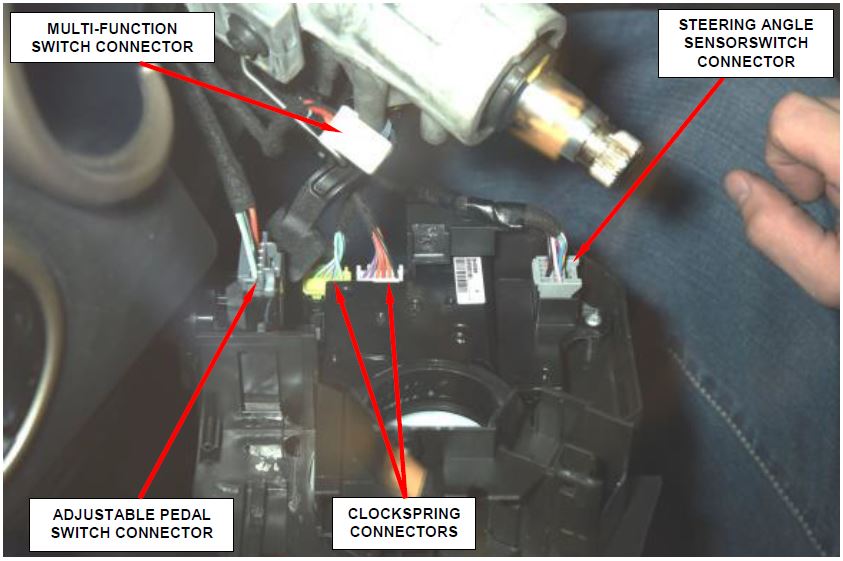
- Pull the clockspring rearward away from the top of the steering column far enough to access and disconnect the following instrument panel wire harness connectors and their wiring retainers from the clockspring (Figure 8):
a. Steering Angle Sensor (SAS) connector.
b. Two clockspring connectors.
c. Adjustable pedal switch connector.
- Remove and discard the clockspring.
Figure 8 – Electrical Connectors
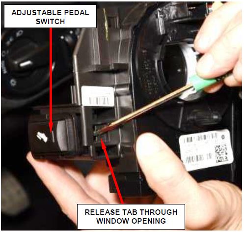
- Release the adjustable pedal switch from the clockspring then remove and save the switch (Figure 9).
Figure 9 – Adjustable Pedal Switch
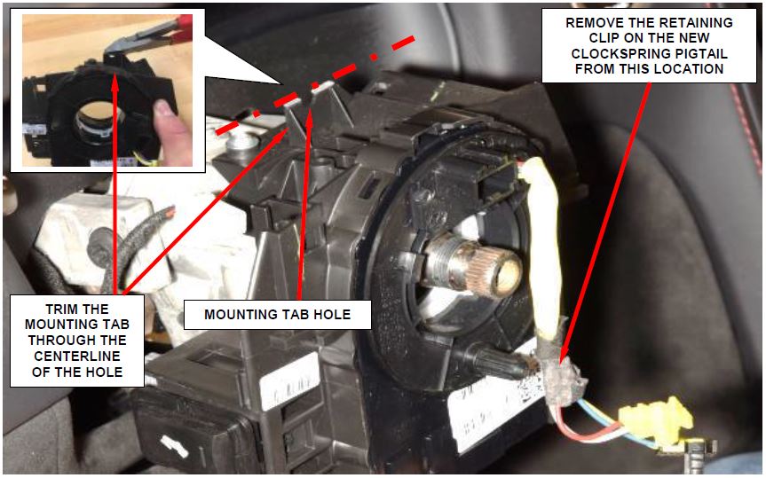
NOTE: Step 21 is required to allow clockspring clearance to the upper steering wheel shroud.
- Using an appropriate cutter, trim the tab at the top of the NEW clockspring through the centerline of the hole as shown (Figure 10).
- Remove and discard the retaining clip from the NEW clockspring pigtail (Figure 10).
Figure 10 – Rework New Clockspring
CAUTION: If the clockspring is not properly centered in relation to the Steering Angle Sensor (SAS), steering wheel, steering shaft and steering gear, it may be damaged or Diagnostic Trouble Codes (DTC) may be set in the SAS. Service replacement clocksprings are shipped pre-centered and with a locking pin installed. This locking pin should not be removed until the clockspring has been installed on the steering column.
- Install the adjustable pedal switch onto the NEW clockspring (Figure 9).
- With the centered clockspring rotor and case secured to each other, or with the plastic locking pin installed, carefully slide the clockspring down over the steering column upper shaft far enough to access and connect the following instrument panel wire harness connectors and their wiring retainers to the clockspring (Figure 8):
a. Steering Angle Sensor (SAS) connector
b. Two clockspring connectors
c. Adjustable pedal switch connector.
- Position the NEW clockspring onto the steering column housing (Figure 7).
- Install and tighten the two screws that secure the clockspring to the steering column housing. Tighten the screws to 3 N·m (25 in. lbs.) (Figure 7).
- Position the multi-function switch housing over the receptacle in the mounting bracket integral to the left side of the NEW clockspring (Figure 6).
- Slide the multi-function switch downward into the mounting bracket receptacle until it is fully seated and the tab of the latch feature integral to the switch housing engages the access window of the bracket.
- Install the upper and lower shrouds onto the steering column (Figure 5).
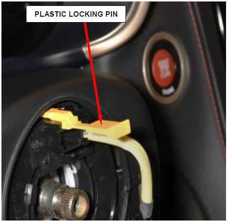
- Remove the plastic locking pin or any other device that is being used to secure the clockspring rotor to the clockspring case to maintain clockspring centering (Figure 11).
NOTE: When installing the steering wheel, be certain to index the engagement dowel/drive pin on the upper surface of the clockspring rotor between the two fins cast into the lower surface of the steering wheel armature hub.
Figure 11 – Plastic Locking Pin
CAUTION: Do not install the steering wheel onto the shaft of the steering column by driving it onto the shaft.
- Feed clockspring wiring leads through hole in rear of steering wheel. Align steering wheel’s wide mounting spline with steering column shaft missing spline area and push wheel onto shaft. Make sure clockspring lines up with back of steering wheel and does not bind.
- Install the NEW steering wheel retaining bolt and tighten it until wheel is fully installed on shaft. Tighten to 54 N·m (40 ft. lbs.).
- Connect the steering wheel wire harness connector to the upper clockspring connector receptacle (Figure 4).
- Place the NEW driver airbag near clockspring wiring and connect horn switch wiring connector (Figure 2).
- Connect squib wires (match colors of connector ends) to driver airbag. Make airbag connection by pressing straight in on connectors. The connector must be fully seated. Feel for positive snap to assure positive connection (Figures 2 and 3).
- Place driver airbag into position and install two mounting screws. Tighten to 105 in. lbs. (12 N·m) (Figure 1).
- Snap closed the screw covers to the access holes on the back of each horizontal spoke of the rear trim cover on the steering wheel.
- Do not connect the negative battery cable at this time. The Supplemental Restraint System (SRS) Verification Test procedure should be performed following service of any SRS component.
- Continue with Section B. Supplemental Restraint System (SRS) Verification Test.
B. Supplemental Restraint System (SRS) Verification Test
NOTE: During the following test, the negative battery cable remains disconnected and isolated during steps 1 and 2 of the Supplemental Restraint System (SRS) Verification Test.
NOTE: The wiTECH scan tool must be used to perform this recall. The wiTECH software is required to be at the latest release level before performing this procedure.
- Connect the wiTECH micro pod II to the vehicle data link connector located under the steering column.
- Using the owner manual locate and disconnect the airbag fuses in the Power Distribution Center.
WARNING: To avoid serious or fatal injury while connecting the battery negative cable, which is located under the driver side floor panel, be certain to remain clear of all airbag deployment paths.
- Connect the battery negative cable and tighten securely. If equipped with an Intelligent Battery Sensor (IBS), connect the IBS connector.
- Turn the ignition switch to the “ON” position and exit the vehicle and close the passenger door.
- Check to be certain that nobody is in the vehicle, then engage airbag fuses in the Power Distribution Center.
- Open the wiTECH Diagnostic application.
- Starting at the “Select Tool” screen, select the row/tool for the wiTECH micro pod II device you are using, then select “Next”.
- Enter your “User id” and “Password”, then select “Finish”.
- Clear all DTC’s in all modules using the wiTECH tool.
NOTE: Any active Diagnostic Trouble Codes (DTC’s) may require an additional key cycle from “ON” to “OFF” to change DTC status from “active” to “stored”.
- Turn the ignition switch to the “OFF” position for about 15 seconds, and then back to the “ON” Observe the airbag indicator in the instrument cluster.
- The airbag indicator in the instrument cluster should illuminate for six to eight seconds, and then go out. This indicates that the SRS is functioning normally and that the repairs are complete. Turn the ignition to the “OFF” position, remove the wiTECH micro pod II and return the vehicle to the customer.
- If the airbag indicator fails to light or the light and stays ON, there is still an active SRS fault or malfunction. Refer to the appropriate diagnostic information to diagnose the problem.
- Remove the wiTECH micro pod II.
- Dispose of all non-deployed airbags in a manner consistent with state, provincial, local and federal regulations. Refer to the Hazardous Substance Control System for proper disposal.
- Return the vehicle to the customer.
Completion Reporting and Reimbursement
Claims for vehicles that have been serviced must be submitted on the DealerCONNECT Claim Entry Screen located on the Service tab. Claims submitted will be used by FCA to record recall service completions and provide dealer payments.
Use the following labor operation number and time allowance:
| Labor Operation Number | Time Allowance | |
|---|---|---|
| Replace DAB, Clockspring and Perform SRS Verification | 19-S7-51-82 | 0.5 hours |
NOTE: See the Warranty Administration Manual, Recall Claim Processing Section, for complete recall claim processing instructions.
Dealer Notification
To view this notification on DealerCONNECT, select “Global Recall System” on the Service tab, then click on the description of this notification.
Owner Notification and Service Scheduling
All involved vehicle owners known to FCA are being notified of the service requirement by first class mail. They are requested to schedule appointments for this service with their dealers. A generic copy of the owner letter is attached.
Enclosed with each owner letter is an Owner Notification postcard to allow owners to update our records if applicable.
Vehicle Lists, Global Recall System, VIP and Dealer Follow Up
All involved vehicles have been entered into the DealerCONNECT Global Recall System (GRS) and Vehicle Information Plus (VIP) for dealer inquiry as needed.
GRS provides involved dealers with an updated VIN list of their incomplete vehicles. The owner’s name, address and phone number are listed if known. Completed vehicles are removed from GRS within several days of repair claim submission.
To use this system, click on the “Service” tab and then click on “Global Recall System.” Your dealer’s VIN list for each recall displayed can be sorted by: those vehicles that were unsold at recall launch, those with a phone number, city, zip code, or VIN sequence.
Dealers must perform this repair on all unsold vehicles before retail delivery. Dealers should also use the VIN list to follow up with all owners to schedule appointments for this repair.
Recall VIN lists may contain confidential, restricted owner name and address information that was obtained from the Department of Motor Vehicles of various states. Use of this information is permitted for this recall only and is strictly prohibited from all other use.
Additional Information
If you have any questions or need assistance in completing this action, please contact your Service and Parts District Manager.
Customer Services / Field Operations
FCA US LLC
This notice applies to your vehicle,
[Model Year Make Model]
VIN XXXXXXXXXXXXXXXXX
S75/NHTSA 16V-736
LOGO
VEHICLE PICTURE
YOUR SCHEDULING OPTIONS
- RECOMMENDED OPTION
Call your authorized Dodge Dealership
- Call the FCA Recall Assistance Center at 1-800-853-1403. An agent can confirm part availability and help schedule an appointment
- Visit our Recall Website, mopar.com or scan below.
QR code
You can find your nearest dealer and review all your scheduling options from this website. You will be asked to provide your Vehicle Identification Number (VIN) to protect and verify your identity. The last eight characters of your VIN are provided above.
DEALERSHIP INSTRUCTIONS
Please reference Safety Recall S75.
IMPORTANT SAFETY RECALL
Driver Airbag Connectors
Dear [Name],
This notification is being sent to you in accordance with the National Traffic and Motor Vehicle Safety Act.
FCA has decided that a defect, which relates to motor vehicle safety, exists in certain [Model Year Make Model] vehicles.
WHY DOES MY VEHICLE NEED REPAIRS?
The Driver Airbag (DAB) inflator connectors on your vehicle [1] may have been misaligned during component assembly. The misaligned DAB connectors result in a misrouting of the DAB airbag wiring harness. This misrouting of the DAB wiring harness may cause the DAB wires to become pinched or damaged. A pinched or damaged DAB wiring harness may cause the DAB system to malfunction and not deploy the DAB during a crash event. If the DAB system malfunctions, the Airbag Warning Light (ABWL) will illuminate. A malfunctioning DAB system could increase the risk of injury or death to the vehicle driver during a crash.
HOW DO I RESOLVE THIS IMPORTANT SAFETY ISSUE?
FCA will repair your vehicle [2] free of charge (parts and labor). To do this, your dealer will replace the DAB and the steering column airbag clockspring on all involved vehicles. In addition, your dealer will require your vehicle for proper check-in, preparation, and check-out during your visit. Your time is important to us; please be aware that these steps may require more time. The estimated repair time is 1 hour. We recommend that you schedule a service appointment to minimize your inconvenience. Please bring this letter with you to your dealership.
TO SCHEDULE YOUR FREE REPAIR CALL 1-800-853-1403
OR YOUR CHRYSLER , DODGE
 , JEEP
 OR RAM
 DEALER TODAY
WHAT IF I ALREADY PAID TO HAVE THIS REPAIR COMPLETED?
If you have already experienced this specific condition and have paid to have it repaired, you may visit www.fcarecallreimbursement.com to submit your reimbursement request online. [3] Once we receive and verify the required documents, reimbursement will be sent to you within 60 days. If you have had previous repairs performed and/or already received reimbursement, you may still need to have the recall repair performed.
We apologize for any inconvenience, but are sincerely concerned about your safety. Thank you for your attention to this important matter.
Customer Assistance/Field Operations
Fiat Chrysler
 Automobiles US LLC
[1] If you no longer own this vehicle, please help us update our records. Call the FCA Recall Assistance Center at 1-800-853-1403 to update your information.
[2] If your dealer fails or is unable to remedy this defect without charge and within a reasonable time, you may submit a written complaint to the Administrator, National Highway Traffic Safety Administration, 1200 New Jersey Ave., S.E., Washington, DC 20590, or you can call the toll-free Vehicle Safety Hotline at 1-888-327-4236 (TTY 1-800-424-9153), or go to safercar.gov.
[3] You can also mail in your original receipts and proof of payment to the following address for reimbursement consideration: FCA Customer Assistance, P.O. Box 218004, Auburn Hills, MI 48321-8007, Attention: Recall Reimbursement.
Note to lessors receiving this recall notice: Federal regulation requires that you forward this recall notice to the lessee within 10 days.
 Loading...
