| “This site contains affiliate links for which OEMDTC may be compensated” |
NHTSA Campaign Number: 14V796
Manufacturer Chrysler Group LLC
Components POWER TRAIN
Potential Number of Units Affected 257,065
Rear Axle Pinion Nut May Loosen at Differential
If the pinion nut loosens, the rear axle may seize, and/or the driveshaft may detach resulting in a loss of vehicle control, increasing the risk of a crash.
SUMMARY:
Chrysler Group LLC (Chrysler
 ) is recalling certain model year 2005 Dodge
 Ram
Ram 1500 trucks manufactured January 28, 2004, to August 3, 2005.
In the affected vehicles, the rear axle pinion nut may loosen due to an undersized spline on the pinion gear.
CONSEQUENCE:
If the pinion nut loosens, the rear axle may seize, and/or the driveshaft may detach resulting in a loss of vehicle control, increasing the risk of a crash.
REMEDY:
Chrysler will notify owners, and dealers will install a retention feature to the pinion nut, free of charge.
The recall began on June 26, 2015, 2015.
Owners may contact Chrysler customer service at 1-800-853-1403.
Chrysler ’s number for this recall is P77.
NOTES:
Owners may also contact the National Highway Traffic Safety Administration Vehicle Safety Hotline at 1-888-327-4236 (TTY 1-800-424-9153), or go to www.safercar.gov.
Check if your Vehicle has a Recall
June 2015
Dealer Service Instructions for:
Safety Recall P77 / NHTSA 14V-796 Rear Axle Pinion Nut
Models
NOTE: This recall applies only to the above vehicles equipped with a 9.25 rear axle (sales code DRB).
Subject
The rear axle pinion nut on about 256,000 of the above vehicles may have been built without an adhesive patch on the pinion nut threads. The lack of this adhesive patch could allow the rear axle pinion nut to loosen and/or the rear driveshaft to separate from the rear axle. A loose pinion nut could cause the rear axle to seize and a separated driveshaft could cause a loss of motive power. Either situation could cause a crash without warning.
Repair
The rear axle pinion nut must be checked for looseness. Rear axles found with a loose pinion nut and/or a seized up axle assembly must be reconditioned. Axles found with a pinion nut that has not loosened will have a pinion nut retainer installed.
Alternate Transportation
Dealers should attempt to minimize customer inconvenience by placing the owner in a loaner vehicle if inspection determines that the rear axle requires reconditioning and the vehicle must be held overnight.
Parts Information
| Part Number | Description |
|---|---|
| CBHKM342AA | Rear Axle Retainer Package |
| Each package contains the following components: | |
| Quantity | Description |
| 1 | Retainer, Pinion Nut |
| 4 | Bolt, Hex Head Flange Locking |
| 2 | Bit, Hex (3/32”) |
Each dealer to whom vehicles in the recall were assigned will receive enough Rear Axle Retaining Packages to service about 20% of those vehicles.
| Part Number | Description |
|---|---|
| CBAKM343AA | Rear Axle Package (sales code DMH / 3.92 ratio) |
| CBAKM344AA | Rear Axle Package (sales code DMD / 3.55ratio) |
| CBAKM345AA | Rear Axle Package (sales code DMC / 3.21ratio) |
| Each package contains the following components: | |
| Quantity | Description |
| 1 | Gear, Ring |
| 1 | Gear, Pinion |
| 1 | Seal, Pinion |
| 1 | Nut, Pinion |
| 1 | Sleeve, Crush |
| 1 | Bearing, Pinion Front |
| 1 | Bearing, Pinion Rear |
| 12 | Bolts, Ring Gear |
| Part Number | Description |
|---|---|
| CBAKM347AA | Pinion Depth Shim Kit |
| 52067614AC | Shaft, Axle |
| 04384227 | Ring, ABS Sensor Tone |
| 03507898AB | Bearing, Axle Shaft |
| 52070427AB | Seal, Axle Shaft |
| 04798912AD | Side Gear Kit (without sales code DSA) |
| 04384222 | Case Assembly (without sales code DSA) |
| 52111420AA | Case Assembly (with sales code DSA) |
| 04874469 | Lube, Rear Axle (SAE 75W-140) |
| 04318060AB | Additive, Limited Slip (with sales code DSA) |
| 05013477AA | Axle-RTV |
| 04318031 | Adhesive, Lock & Seal (medium strength threadlocker) |
| 04883065 | Compound, Gear Marking |
| 05012249AB | Lubricant, Nickel Anti-Seize (NOTE: one bottle of anti-seize can repair 20 vehicles) |
Only if the original ring and pinion is being reused, order the parts below:
| Part Number | Description |
|---|---|
| CBAKM348AA | Seal, Pinion |
| CBAKM349AA | Nut, Pinion |
| 03507678 | Sleeve, Crush |
| 05072498AA | Bearing, Pinion Front (bearing and cup) |
| 05017438AA | Bearing, Pinion Rear (bearing and cup) |
| 05072506AA | Bearings, Differential Carrier Side (contains two bearings and two cups) |
Special Tools
The following special tools are required to perform this repair:
| Holder, Position |
| Adjuster Wrench |
| Puller |
| Puller |
| Adapter |
| Puller |
| Remover |
| Handle |
| Remover |
| Installer |
| Installer |
| Pinion Height Block |
| Pinion Block |
| Screw |
| Cone Nut |
| Arbor Discs |
| Arbor |
| Dial Indicator |
| Scooter Block |
| Installer |
| Handle |
| Installer |
| Installer |
| Installer, bearing |
| Bearing Remover |
| Foot |
| Installer |
| Installer |
Service Procedure
A. Inspect Rear Axle Pinion Nut
- If the rear axle has locked up and/or has completely failed, continue to Section B. Recondition Rear Axle. If the axle seems to be functioning properly, continue with Step 2 of this inspection procedure.
- Lift the vehicle on an appropriate hoist.
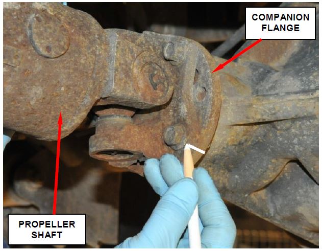
- Mark the propeller shaft-to-companion flange to maintain orientation during installation of the propeller shaft (Figure 1).
Figure 1 – Mark Propeller Shaft-to-Companion Flange Orientation
- Remove and discard the four rear propeller shaft retaining bolts.
- Separate the propeller shaft from the companion flange and set the end of the propeller shaft onto a jack stand.
CAUTION: Do not allow the propeller shaft to hang from the transmission/transfer case unsupported.
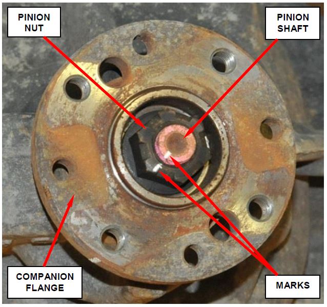
- Place a mark on the pinion nut and pinion shaft as shown in Figure 2.
Figure 2 – Mark Pinion Nut and Pinion Shaft
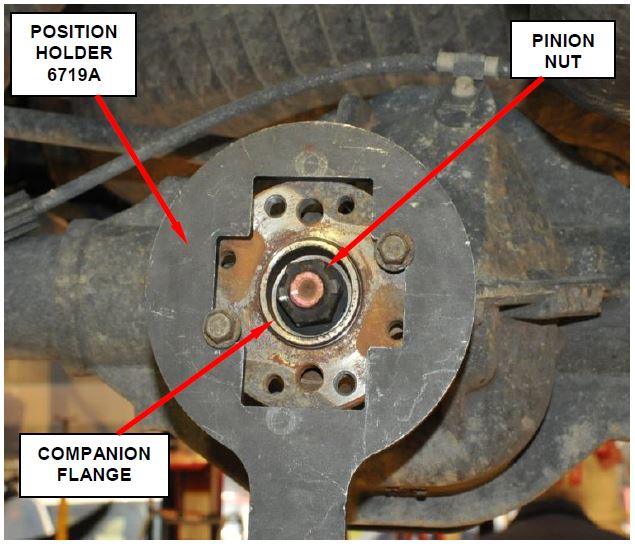
- Place the Position Holder 6719A against the companion flange and install a bolt and washer in the threaded holes (Figure 3). Tighten the bolts so the Position Holder 6719A is held to the flange.
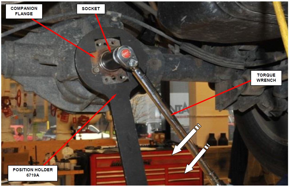
- Using a torque wrench, tighten the pinion nut to 50 ft. lbs. (68 N·m) (Figure 4).
Figure 3 – Install Position Holder 6719A
Figure 4 – Attempt to Tighten Pinion Nut
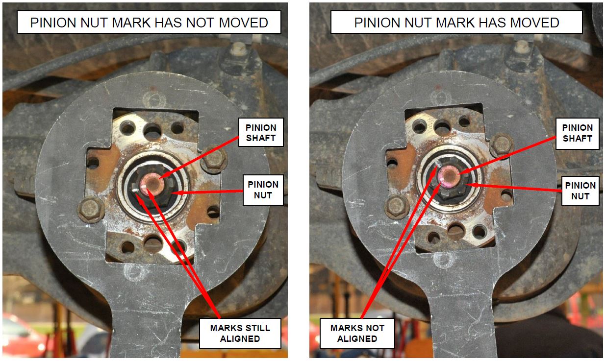
- Inspect the mark placed on the pinion nut and pinion shaft:
- If the pinion nut mark has not moved (Figure 5), continue with Step 10 of this procedure.
- If the pinion nut mark has moved (Figure 5), the ring and pinion must be replaced. Continue with Section B. Recondition Rear Axle.
- Using a torque wrench, tighten the pinion nut to 100 ft. lbs. (135 N·m).
- Again, inspect the mark placed on the pinion nut and pinion shaft:
- If the pinion nut mark has not moved (Figure 5), continue with Section C. Install Pinion Nut Retainer Ring.
- If the pinion nut mark has moved (Figure 5), the ring and pinion must be inspected and/or replaced if necessary. Continue with Section B. Recondition Rear Axle.
Figure 5 – Inspect for Pinion Nut Movement on the Pinion Shaft
B. Recondition Rear Axle
NOTE: Only rear axles with a loose pinion nut and/or a complete axle failure, as determined by the inspection in Section A, require reconditioning. Very few vehicles are expected to require rear axle reconditioning.
- Lift the vehicle on an appropriate hoist.
- Remove and save the differential cover.
- Remove and save both rear tire and wheel assemblies.
- Remove both axle shafts using the following procedure:
a. Remove and save the brake calipers, adapters, and rotors.
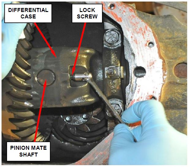
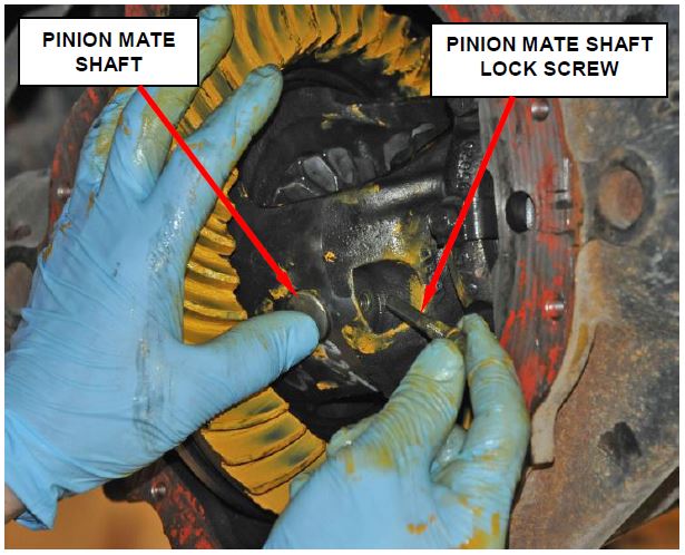
b. Rotate the differential case so pinion mate shaft lock screw is accessible (Figure 6).
c. Remove and save the lock screw and pinion mate shaft from the differential case (Figure 6).
Figure 6 – Remove Lock Screw and Pinion Mate Shaft
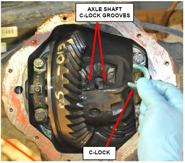
d. Push the axle shafts inward and remove C-locks from the axle shafts (Figure 7).
e. Carefully remove the axle shafts to prevent damage to the axle shaft bearing and axle shaft seal in the axle tube.
Figure 7 – Axle Shaft C-Locks
- For axles that were locked up, inspect the axle shaft splines and bearing race for damage.
- If the axle shaft(s) splines are not twisted or broken and/or the bearing race on the axle shaft is not pitted or gouged, continue with Step 7 of this procedure.
- If the axle shaft(s) splines are twisted or broken and/or the bearing race on the axle shaft is pitted or gouged, continue with Step 6 of this procedure.
- For axles that were locked up and have damaged axle shaft splines or bearing race, use the following procedure to replace the axle shaft bearing(s).
NOTE: Only rear axles with a complete axle failure (locked up), may require axle shaft and axle shaft bearing replacement. Very few vehicles are expected to require axle shaft replacement.
a. Remove and discard axle shaft bearing(s) with Bearing Remover 6310 and Foot 6310-9.
b. Install the axle shaft bearing with Installer C-4198 and Handle C-4171. Drive bearing in until the tool contacts the axle
CAUTION: The axle shaft bearing is installed into the axle tube with the bearing part number against the installer.
c. Coat the lip of the new axle seal with axle lubricant and install with Installer C-4076-B and Handle C-4735.
d. Continue with Step 7 of this procedure.
- Mark the differential housing and the bearing caps for installation reference.
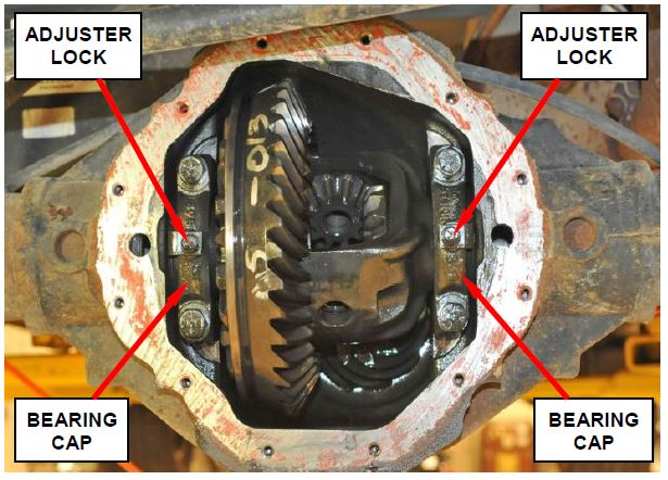
- Remove the bearing threaded adjuster lock from each bearing cap (Figure 8).
- Loosen the differential bearing cap bolts (Figure 8).
Figure 8 – Adjuster Locks and Bearing Caps
- Insert Adjuster Wrench C-4164 into the end of the axle tube and loosen both of the differential bearing adjusters.
- Hold the differential case while removing the bearing caps and adjusters.
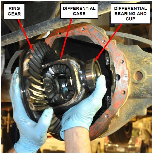
- Remove and save the differential case from the axle housing (Figure 9).
Figure 9 – Differential Case
- For differentials that require ring and pinion replacement, remove and discard the ring gear attaching bolts. Then drive the ring gear off the differential case with a soft hammer. Discard the original ring gear.
NOTE: The ring gear bolts have left-handed threads.
- Remove the pinion from the differential case using the following procedure:
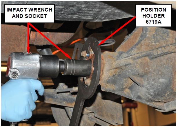
a. Place the Position Holder 6719A against the companion flange and install a bolt and washer into the threaded holes (Figure 10). Tighten the bolts so the Position Holder 6719A is held to the flange.
Figure 10 – Pinion Nut
b. Use Position Holder 6719A to hold the companion flange and remove the pinion nut (Figure 11).
c. Remove the Position Holder 6719A from the companion flange.
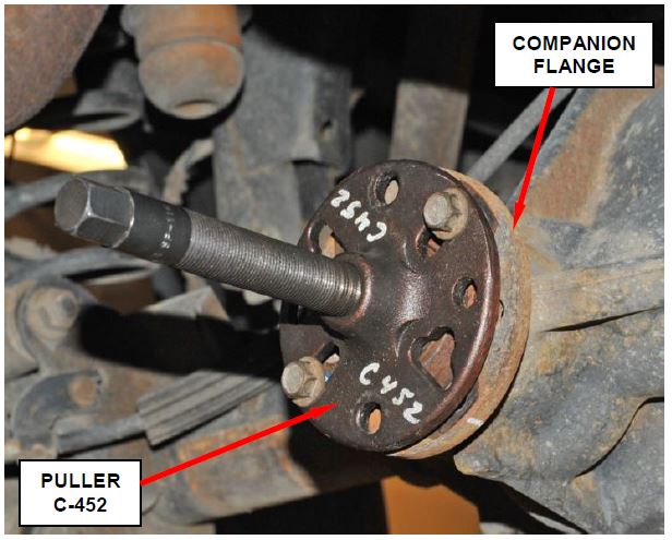
d. Remove the companion flange with Puller C-452 (Figure 11).
Figure 11 – Companion Flange Puller C-452
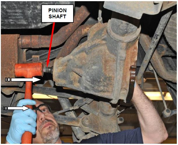
e. While holding the pinion gear from the differential housing opening, hit the end of the pinion shaft with a soft hammer to remove (Figure 12).
Figure 12 – Pinion Gear Removal
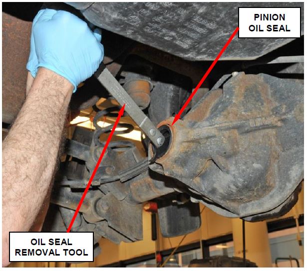
f. Remove and discard the pinion oil seal using a pry tool (Figure 13).
g. Remove the front pinion bearing and the oil slinger, if equipped.
Figure 13 – Pinion Oil Seal Removal
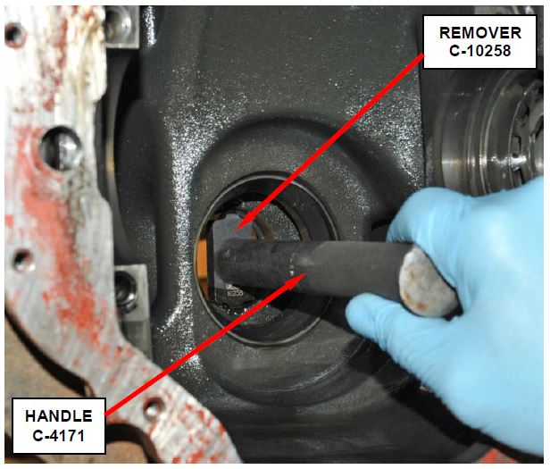
h. Remove the front pinion bearing cup with Remover C-10258, Handle C-4171 and a hammer (Figure 14).
Figure 14 – Front Pinion Bearing Cup Removal
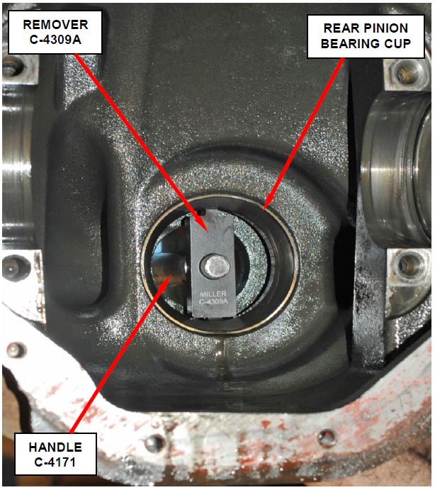
i. Remove the rear pinion bearing cup from the housing with Remover C-4309A, Handle C-4171 and a hammer (Figure 15).
NOTE: Remover C-4309A must be placed into position in the differential case before attaching the C-4171 handle.
Figure 15 – Rear Pinion Bearing Cup Removal
- Clean the housing cavity with flushing oil, light engine oil and/or a lint free cloth.
CAUTION: Do not use steam, kerosene or gasoline to clean the differential housing.
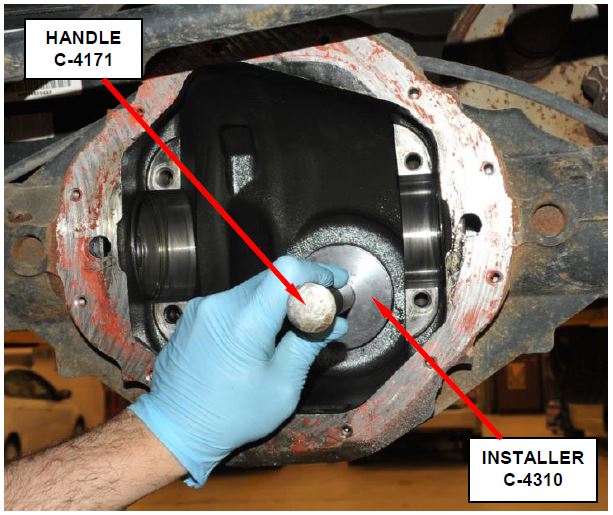
- Install the rear pinion bearing cup with Installer C-4310, Handle C-4171 and a hammer (Figure 16).
Figure 16 – Rear Pinion Bearing Cup Installation
NOTE: Be sure that the rear pinion bearing cup is fully seated in the differential case.
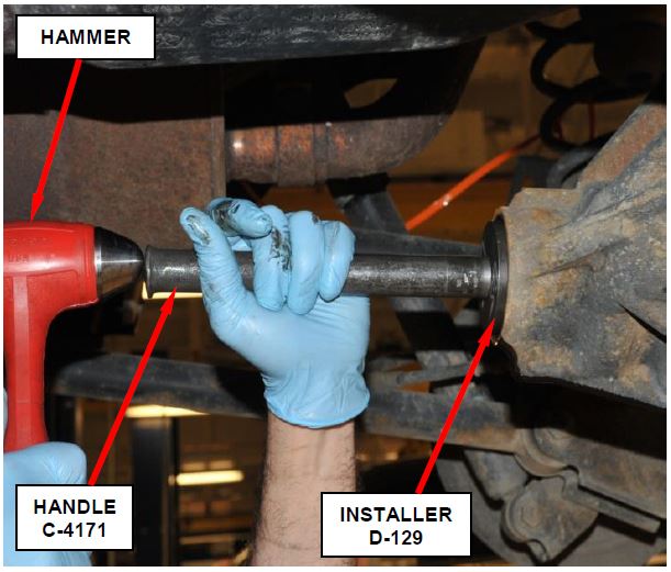
- Install the front pinion bearing cup with Installer D-129, Handle C-4171 and a hammer (Figure 17).
NOTE: Be sure that the front pinion bearing cup is fully seated in the differential case.
CAUTION: Failure to seat both the front and/or rear pinion bearing cups completely in the differential case will cause the pinion bearing preload to decrease after the axle has been put into service. Low pinion bearing preload will cause axle failure.
Figure 17 – Front Pinion Bearing Cup Installation
- Use the following procedure to set pinion depth:
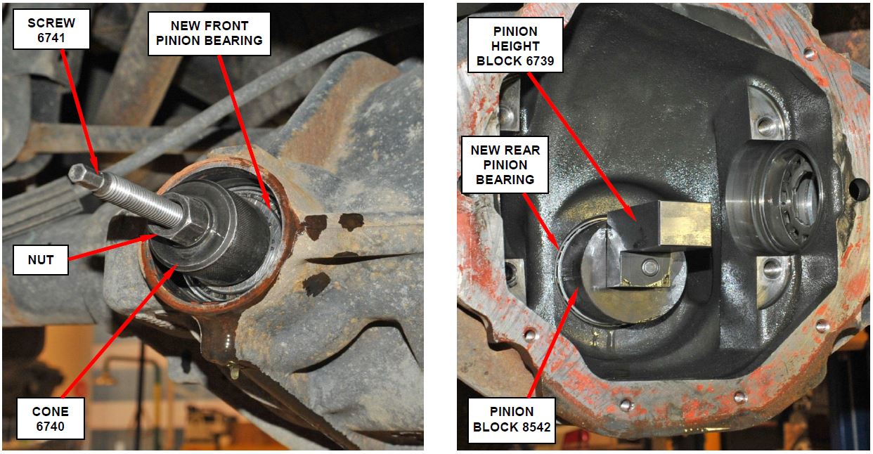
a. Assemble the Pinion Height Block 6739, Pinion Block 8542 and new rear pinion bearing onto Screw 6741 (Figure 20).
b. Insert the Pinion Block 8542, Pinion Height Block 6739, new rear bearing, and Screw 6741 into the housing through pinion the bearing cups (Figure 18 and 19).
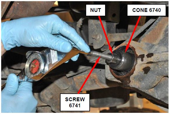
Figure 18 – Check Turning Torque
NOTE: Do not lubricate the front or rear pinion bearing with gear lubricant before installing. All turning torque specifications are calculated with dry bearings.
c. Install new front pinion bearing and Cone 6740 and nut onto the Screw 6741). Tighten the cone-nut until the turning torque of the screw is 22 in. lbs. (2.5 N·m) (Figure 18 and 19).
Figure 19 – Pinion Depth Tool Installation
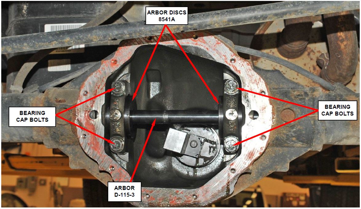
Figure 20 – Arbor Discs 8541A and Arbor D-115-3
d. Place the Arbor Discs 8541A on Arbor D-115-3 in position in the housing side bearing cradles. Install the differential bearing caps on the arbor discs and tighten the bearing cap bolts to 80 ft. lbs. (108 N·m) (Figure 20).
NOTE: Follow the printed instructions on the arbor discs for proper orientation and installation of the discs.
Figure 21 – Zeroing the Dial Indicator
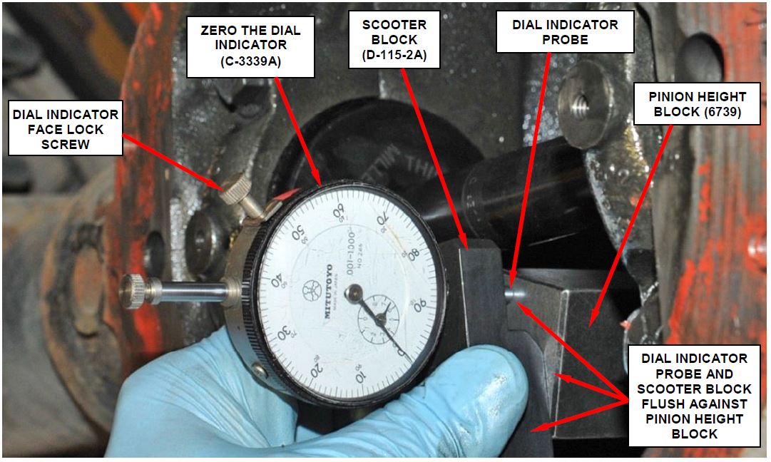
e. Assemble the Dial Indicator C-3339A into Scooter Block D-115-2A and secure the set screw (Figure 21).
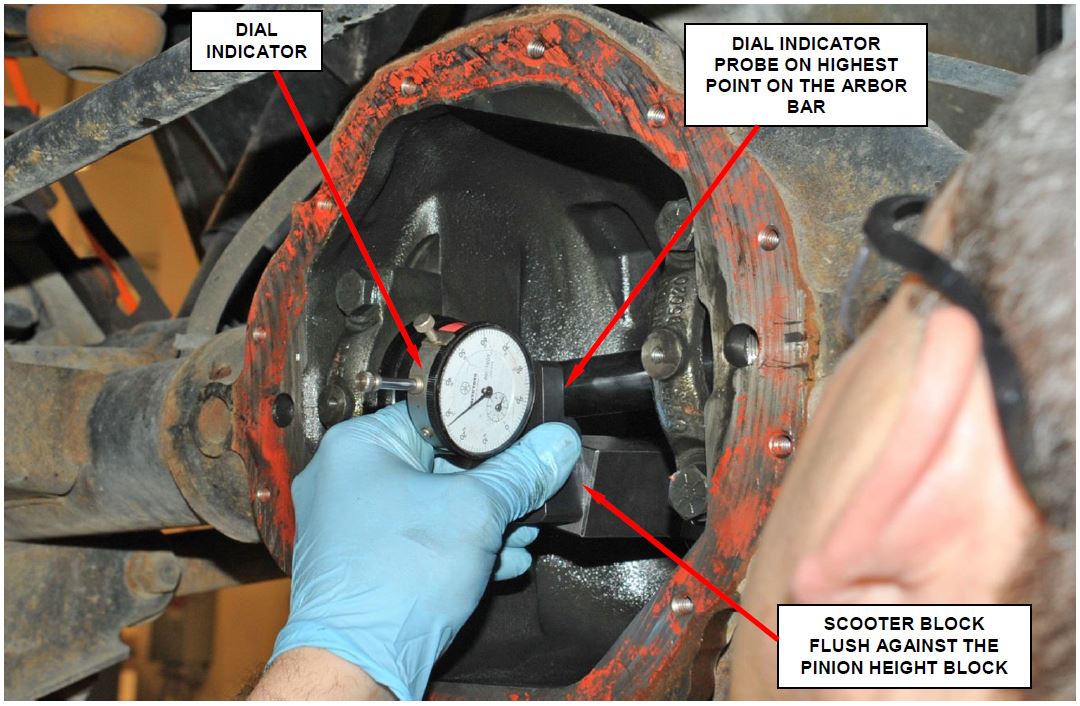
f. Place the Scooter Block/Dial Indicator in position in axle housing so the Dial Indicator probe and the Scooter Block are flush against the rearward surface of the Pinion Height Block (Figure 21). While holding the Scooter Block in place and zero the Dial Indicator. Tighten the Dial Indicator face lock screw.
Figure 22 – Measure pinion Depth Requirement
g. Slide the Dial Indicator probe across the gap between the Pinion Height Block and the Arbor Bar with the Scooter Block against the Pinion Height Block (Figure 22). Continue moving the dial probe to the crest of the Arbor Bar and record the highest reading obtained on the Dial Indicator.
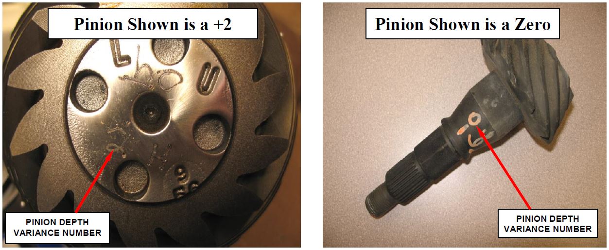
h. Select a shim equal to the Dial Indicator reading plus or minus the pinion depth variance number marked on the pinion gear. For example:
- If the depth variance is -3, add 0.003 in. to the Dial Indicator reading.
- If the depth variance is +3, subtract 0.003 in. from the Dial Indicator reading.
NOTE: Some pinion gears will be marked on the end of the pinion gear head and some will be marked with a paint pencil on the pinion shaft (Figure 23).
i. Subtract two thousands (0.002) from the shim thickness that was determined in the previous step to compensate for pinion bearing growth.
NOTE: Bearing growth occurs when the bearing is pressed onto the pinion shaft.
Figure 23 – Pinion Depth Variance Markings
- Install the new front pinion bearing, and oil slinger if equipped, into the differential case.
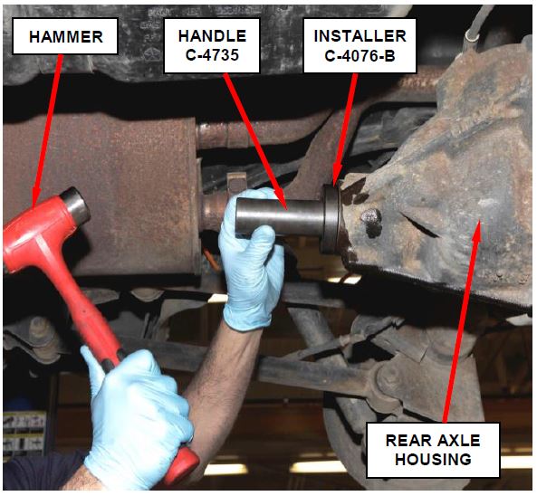
- Apply a light coating of gear lubricant on the lip of the new pinion oil seal. Install the pinion seal with Installer C-4076-B, Handle C-4735 and a hammer (Figure 24).
Figure 24 – Install Pinion Seal
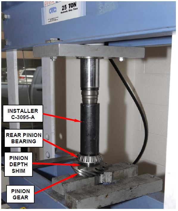
- Install the pinion depth shim selected in Step 19i. on the pinion gear shaft (Figure 25).
NOTE: If the original pinion is being reused, first remove and discard the original rear pinion bearing and pinion depth shim.
- Using a hydraulic press, install the new rear pinion bearing on the pinion shaft with Installer C-3095-A (Figure 25).
Figure 25 – Press Rear Pinion Bearing onto Pinion Shaft
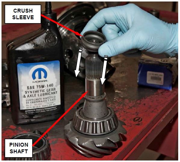
- Install a new crush sleeve on the pinion shaft (Figure 26).
- Install the pinion gear into the differential case.
Figure 26 – Install New Crush Sleeve
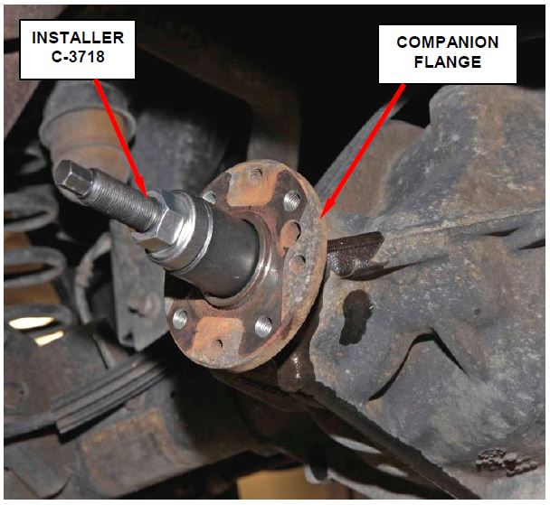
- Install the companion flange with Installer C-3718 and Position Holder 6719A (Figure 27).
Figure 27 – Companion Flange Installer C-3718
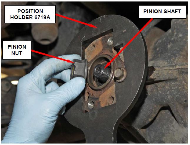
- Install a new pinion nut onto the pinion shaft (Figure 28).
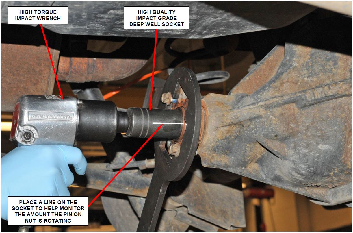
- Hold the companion flange with Position Holder 6719A and tighten the pinion nut, with a high quality impact wrench, until there is no free-play in the bearings (Figure 29).
- Remove the Position Holder 6719A from the companion flange.
- Rotate the companion flange/pinion several times to seat the pinion bearings.
Figure 28 – Install New Pinion Nut
Figure 29 – Tighten Pinion Nut until there is no Free-play in the Pinion Bearings
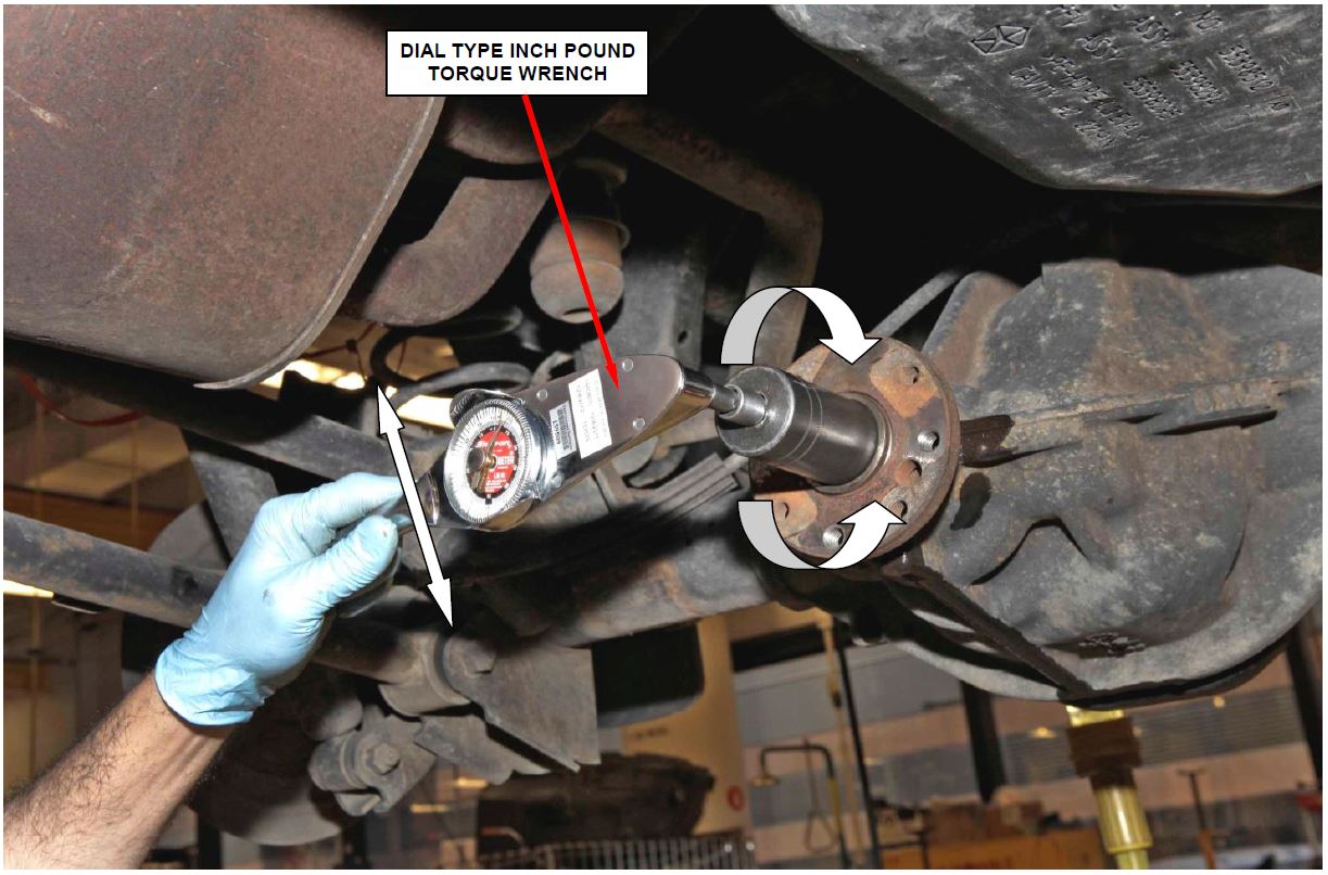
- Measure the pinion turning torque with a “dial type” inch pound torque wrench. The correct pinion turning torque range is 15 – 35 in. lbs. (1.7 – 4.0 N·m). The preferred setting is 25 in. lbs. (2.8 N·m).
- If the pinion turning torque is too low, install the Position Holder 6719A and tighten the pinion nut in small increments. Then remove the Position Holder, rotate the flange several times and recheck the pinion turning torque. Repeat, if necessary, in small increments until the correct pinion turning torque is achieved (Figure 31).
- If the pinion turning torque is too high, never loosen the pinion nut to decrease pinion bearing turning torque. If the pinion turning torque is exceeded a new crush sleeve must be installed.
NOTE: Placing a line on the side of the socket will help to determine how much the socket turned while tightening the pinion nut in small increments (Figure 30).
Figure 30 – Check Turning Torque with Dial Type Inch Pound Torque Wrench
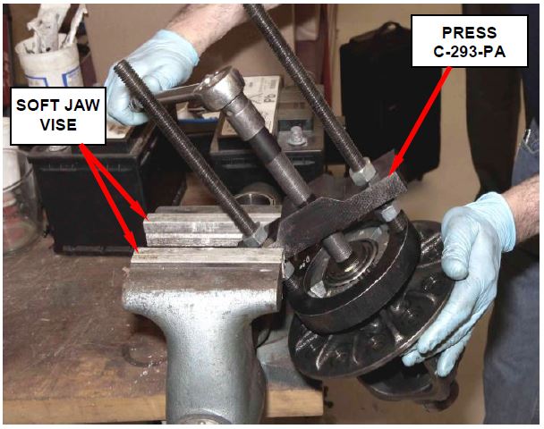
- Inspect, and replace if required, the differential side bearings. Use Puller/Press C-293-PA, Block Set/Puller C-293-47 and Adapter/Bearing/Gear C-293-3 (Figure 31).
NOTE: For vehicles with a Trac-Lok unit, if damaged axle shaft splines were found, replace the Trac-Lok unit.
Figure 31 – Differential Side Bearing Removal
- Position the ring gear and ABS sensor tone ring on the differential case and start two new ring gear bolts. This will provide case-to-ring gear bolt hole alignment.
- Secure the differential case in a soft-jawed vise.
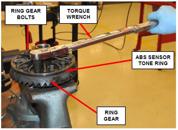
- Install all of the new ring gear bolts and alternately tighten to 115 ft. lbs. (156 N·m) (Figure 32).
CAUTION: Never reuse the original ring gear bolts.
Figure 32 – Tighten Ring Gear Bolts
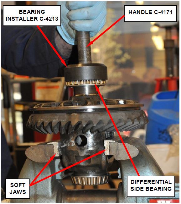
- If replaced, install the differential side bearings with Bearing Installer C-4213, Handle C-4171 and a hammer (Figure 33).
- Place the differential case/ring gear assembly into the differential housing.
- Install the bearing caps and bolts. Lightly snug the bearing cap retaining bolts.
CAUTION: Ensure that the differential bearing caps are installed on the correct side by verifying the markings made in Step 8.
Figure 33 – Install Differential Side Bearings
- Turn each thread adjuster inward with Adjuster Wrench C-4164 until the differential bearing end-play is eliminated and the ring gear backlash is approximately 0.001 in. (0.025 mm). Seat the bearing cups by rapidly rotating the ring gear a half turn back and forth several times.
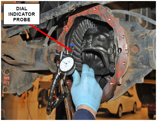
- Install a Dial Indicator (C-3339) with probe positioned against a ring gear tooth (Figure 34). Measure and record backlash at 4 positions, 90 degrees apart around the ring gear. Mark the lowest backlash position on the ring gear and make all backlash measurements at this location.
Figure 34 – Measure Backlash in 4 Positions
- Loosen the left-side threaded adjuster and tighten the right-side threaded adjuster evenly with Adjuster Wrench C-4164 to obtain a backlash of 0.003 – 0.004 in. (0.076 – 0.102 mm).
- Tighten both adjusters to 10 ft. lbs. (14 N·m). Seat the differential bearing cups by rapidly rotating the ring gear a half turn back and forth several times.
- Tighten the differential bearing cap bolts 100 ft. lbs. (136 N·m).
- Tighten the right-side threaded adjuster to 75 ft. lbs. (102 N·m). Seat the differential bearing cups by rapidly rotating the pinion gear a half turn back and forth several times. Continue this procedure until right-side adjuster torque remains a constant 75 ft. lbs. (102 N·m).
- Measure the ring gear backlash. Ring gear-to-pinion gear backlash should be 0.005 – 0.008 in. (0.12 – 0.20 mm).
- If backlash is less than 0.005 in. (0.12 mm) increase the torque on the right-side threaded adjuster until the specified ring gear-to-pinion backlash is obtained.
- If backlash is more than 0.008 (0.20 mm) repeat procedure from the beginning (Step 41).
- Tighten the left-side threaded adjuster to 75 ft. lbs. (102 N·m). Seat the differential bearing cups by rapidly rotating the pinion gear a half turn back and forth several times. Continue this procedure until left-side adjuster torque remains a constant 75 ft. lbs. (102 N·m).
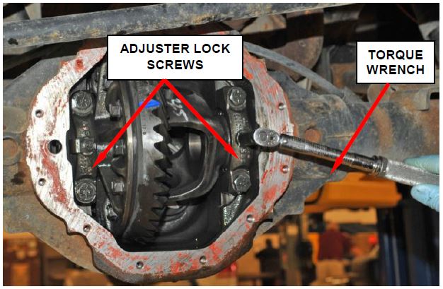
- Install the threaded adjuster locks and tighten the lock screws to 90 in. lbs. (10 N·m) (Figure 35).
- Measure the backlash at 4 positions around the ring gear, 90 degrees apart. The maximum ring gear backlash variation is 0.003 in. (0.076 mm).
Figure 35 – Tighten Lock Screws
- Use the following procedure to perform a gear pattern check:
a. Wipe clean each tooth of the ring gear.
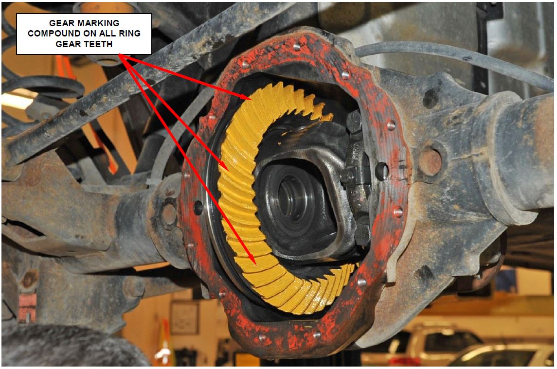
b. Apply Mopar gear marking compound to all of the ring gear teeth (Figure 36).
c. Create an additional 10 ft. lbs. (14 N·m) pinion rotating torque.
d. Rotate the pinion yoke four (4) full revolutions in each direction.
Figure 36 – Apply Gear Marking Compound to Ring Gear Teeth
e. Read gear tooth contact pattern.
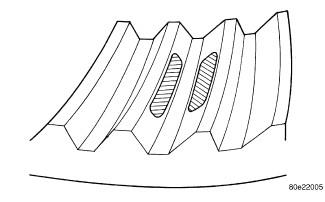
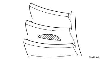
- The gear contact pattern is correct. Backlash and pinion depth is correct (Figure 37).
Figure 37
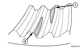
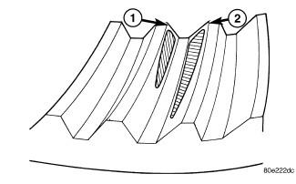
- The ring gear is too far away from the pinion gear, coast side toe (1) and drive side heel (2). Decrease the backlash, by moving the ring closer to the pinion gear using the adjusters (Figure 38).
Figure 38
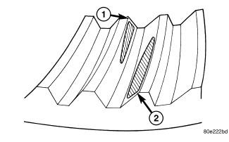
- The ring gear is too close to the pinion gear, drive side toe (1) and coast side heel (2). Increase backlash, by moving the ring away from the pinion gear using the adjusters (Figure 39).
Figure 39
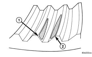
- The ring gear is too far away from the pinion gear, drive side heel (1) and coast side heel (2). Decrease the backlash, by moving the ring closer to the pinion gear using the adjusters (Figure 40).
Figure 40
- The ring gear is too close to pinion gear, drive side toe (1) and coast side toe (2). Increase the backlash, by moving the ring away from the pinion gear using the adjusters (Figure 41).
Figure 41
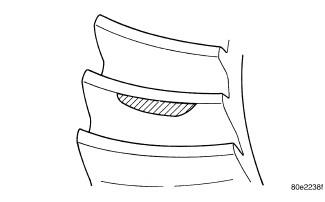
- The pinion gear is set too low. Increase the pinion gear height, by increasing the pinion depth shim thickness (Figure 42).
Figure 42
- The pinion gear is set too Decrease the pinion depth, by decreasing the pinion depth shim thickness (Figure 43).
Figure 43
- For axles that were locked up, inspect for damaged splines inside the side gears. Replace the side gears if required.
NOTE: If the axle shaft(s) were inspected and one or both were found to be damaged, vehicles without Trac-Lok must have the side gears replaced.
NOTE: If the axle shaft(s) were inspected and one or both were found to be damaged, vehicles with Trac-Lok must have the case (Trac-Lok unit) replaced.
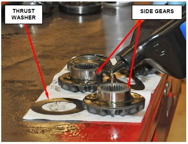
- For vehicles without Trac-Lok, lubricate the side gears and thrust washers with axle lube before installing them into the differential case (Figure 44).
Figure 44 – Lubricate Side Gears and Thrust Washers
- For vehicles without Trac-Lok, install the differential side gears into the differential case housing.
- Install the right and left side axle shafts using the following procedure:
a. Lubricate the bearing bore and seal lip with gear lubricant.
b. Install the axle shafts and engage into side gear splines.
CAUTION: Use care when installing the axle shafts to prevent the shaft splines from damaging axle shaft seal.
c. Insert the C-lock in the end of the axle shafts, then pull the axle shafts outward to seat the C-lock in the side gears (Figure 7).
Figure 45 – Pinion Mate Shaft Lock Screw
d. Insert the pinion shaft into the differential case and through the thrust washers and differential pinions (Figure 45).
e. Align the hole in pinion mate shaft with hole in the differential case and install the lock screw with Mopar threadlocker (P/N 04318031) on the threads. Tighten the lock screw to 8 ft. lbs. (11 N·m) (Figure 45).
- Install the differential cover using the following procedure:
a. Clean the differential housing-to-differential cover sealing surface.
b. Clean the differential cover.
c. Apply a ¼ in. (6.35mm) bead of Mopar Axle RTV to the differential cover.
CAUTION: If the differential cover is not installed within 3 to 5 minutes, the differential cover must be cleaned and new RTV applied. Failure to follow these instructions will result in a gear lubricant leak.
d. Install the differential cover. Tighten the differential cover bolts in a crisscross pattern to 30 ft. lbs. (41 N·m).
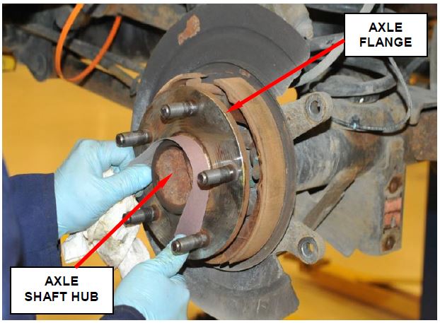
- For trucks with the original axle shaft(s), using a piece of emery cloth, remove all corrosion from the axle shaft hubs (Figure 46).
Figure 46 – Clean Axle Flange Hub
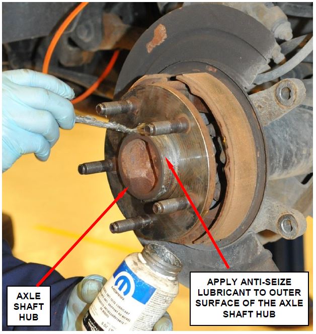
- Apply a light coat of Mopar Nickel Anti-Seize Lubricant to both axle shaft hubs (Figure 47).
- Install the brake rotors, caliper adapters and calipers. Tighten the caliper adapter bolts to 120 ft. lbs. (163 N·m).
Figure 47 – Apply Anti-Seize Lubricant to Axle Shaft Hub
- For vehicles equipped with a Trac-Lok differential, install one bottle of Mopar limited slip additive.
- Fill the differential with Mopar SAE 75W-140 Synthetic Gear & Axle Lubricant to the bottom of the fill hole in the differential cover.
- Install the rear axle lubricant rubber fill plug into the differential cover.
- Continue with Section C. Install Pinion Nut Retainer
C. Install Pinion Nut Retainer Ring
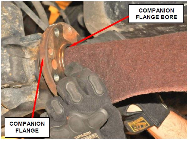
- Thoroughly clean the companion flange bore around the pinion nut (Figure 48).
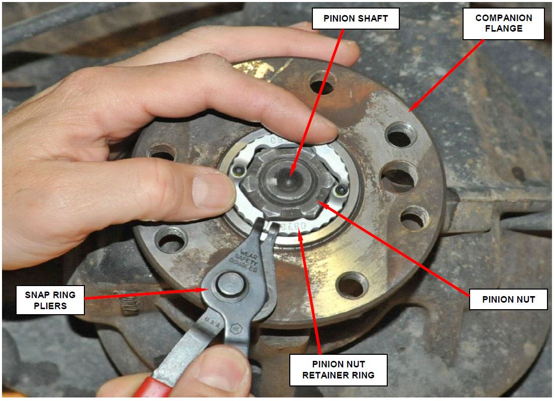
- Using snap ring pliers, install the pinion nut retainer ring (Figure 49).
Figure 48 – Clean Companion Flange Bore
Figure 49 – Install Pinion Nut Retainer Ring
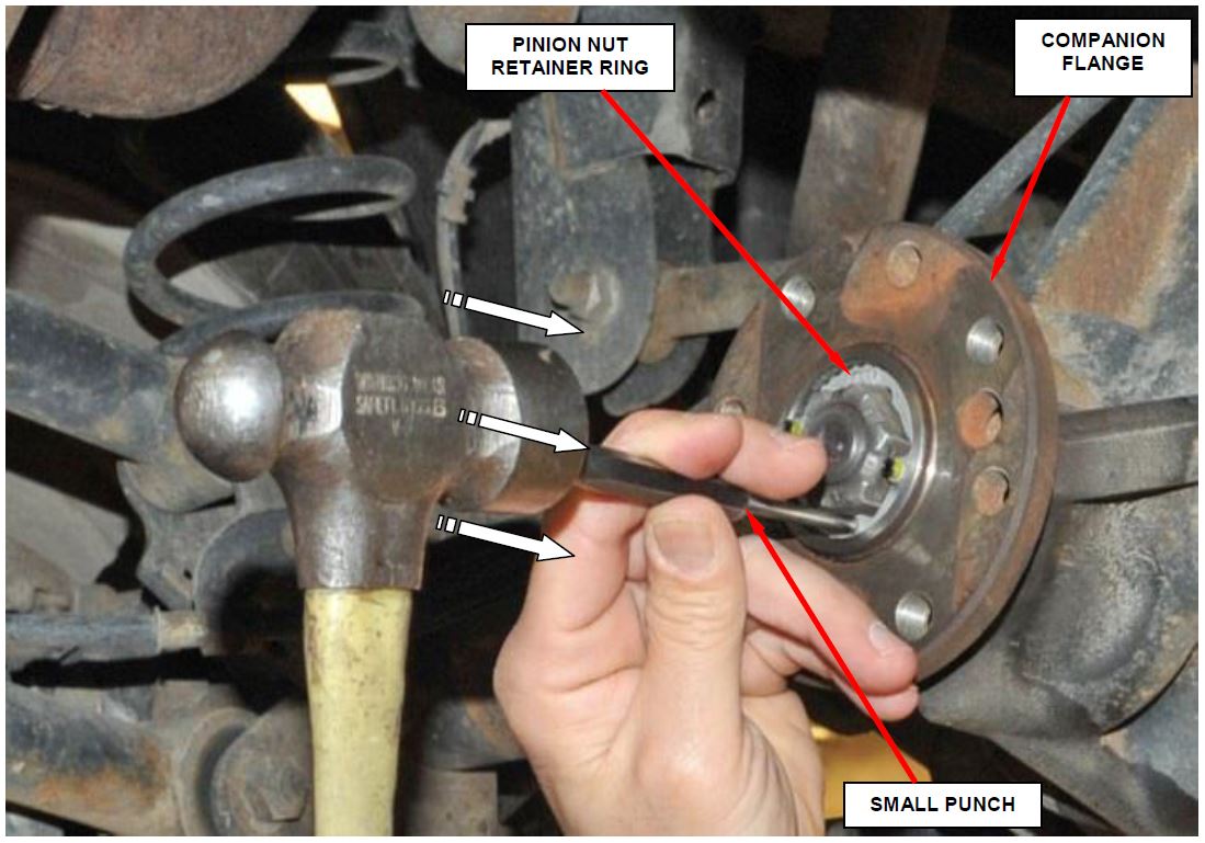
- Using a small punch, gently tap the face of the pinion nut retainer ring to ensure that it is completely seated in the companion flange bore (Figure 50).
Figure 50 – Gently Tap the Face of the Pinion Nut Retainer Ring to Ensure it is Fully Seated in the Companion Flange Bore
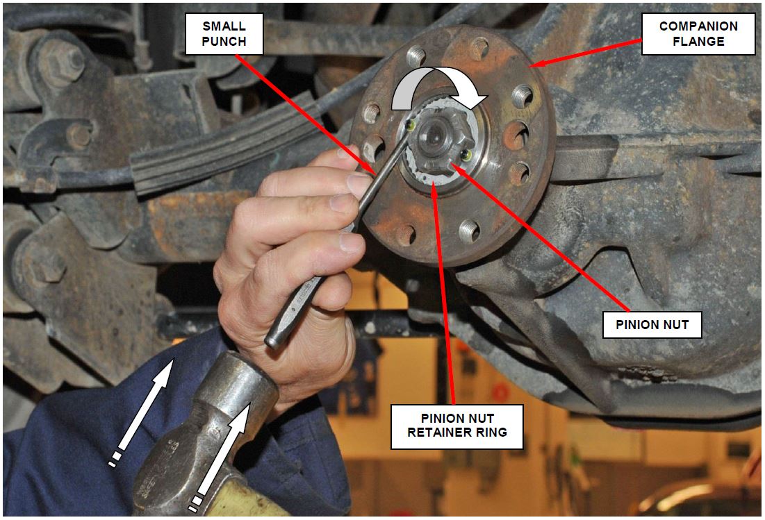
- Using a small punch and hammer, gently rotate the pinion nut retainer ring clockwise until the pinion nut retainer ring seats against the flats/corners of the pinion nut (Figure 51).
Figure 51 – Rotate the Pinion Nut Retainer Ring Clockwise until Seated Against the Pinion Nut Flats/Corners
CAUTION: Use extreme care not to damage the retaining ring when rotating it into position with a punch and hammer.
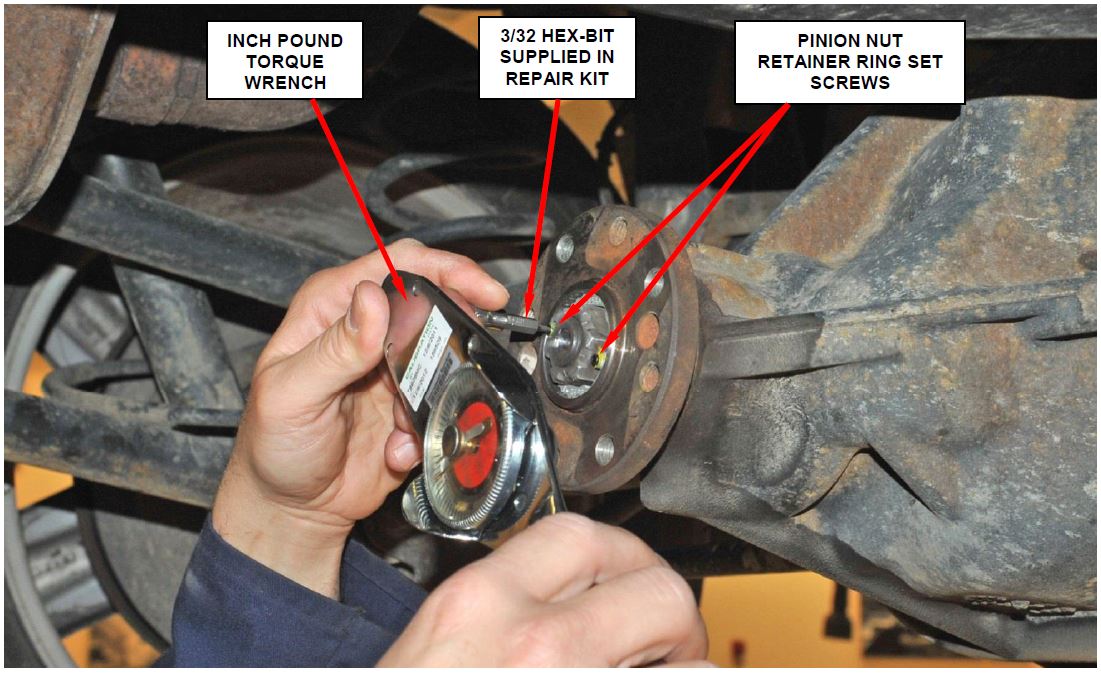
- Using the supplied hex-bits, snug the two set screws on the pinion nut retainer ring.
- Using an inch pound torque wrench, tighten each of the set screws on the pinion nut retainer ring in 5 in. lbs. increments, alternating back and forth (Figure 52). Continue alternating back and forth increasing the torque on the torque wrench by 5 in. lbs. until 45 in. lbs. (5 N·m) is obtained on both set screws.
Figure 52 – Tighten Set Screws in 5 in. lbs. Increments Alternating Back and Forth Until 45 in. lbs. (5 N·m) is Obtained on Each Set Screw
CAUTION: Failure to alternate between the two set screws during the tightening process will cause pinion nut retainer ring damage.
CAUTION: The supplied hex-bits will be stressed to their limit during the tightening process. Do not exceed 45 in. lbs. (5 N·m), hex-bit breakage will occur. It is not uncommon for the hex-bit to break occasionally when the tightening torque reaches 45 in. lbs. (5 N·m). If the hex-bits continuously break during installation, have your torque wrench calibration checked and adjusted as required.
- Install the propeller shaft into position. Install new propeller shaft retaining bolts and tighten them to 85 ft. lbs. (115 N·m).
- For vehicles that had the rear axle reconditioned, partially lower the vehicle from the hoist.
- For vehicles that had the rear axle reconditioned, install the rear tire and wheel assemblies. Tighten the lug nuts to 130 ft. lbs. (176 N·m).
- Lower the vehicle from the hoist.
- For vehicles that had the rear axle reconditioned, perform the following additional steps:
a. Before moving the vehicle, apply the brakes several times to ensure that the rear brake pads are against the brake rotor.
b. Road test the vehicle to ensure that the rear axle functions properly.
c. For vehicles with a Trac-Lok differential, road test the vehicle and make 10 to 12 slow figure-eight turns in an empty parking lot or other safe area. This maneuver will pump the lubricant through the clutch discs to eliminate a possible rear axle chatter noise complaint.
Completion Reporting and Reimbursement
Claims for vehicles that have been serviced must be submitted on the DealerCONNECT Claim Entry Screen located on the Service tab. Claims submitted will be used by FCA to record recall service completions and provide dealer payments.
Use the following labor operation numbers and time allowances:
| Labor Operation Number | Time Allowance | |
|---|---|---|
| Check pinion nut for looseness and install pinion nut retainer | 03-P7-71-82 | 0.4 hours |
| Check pinion nut for looseness, recondition rear axle (using new gear set) and install pinion nut retainer | 03-P7-71-83 | 4.4 hours |
| Check pinion nut for looseness, recondition rear axle (using original gear set) and install pinion nut retainer | 03-P7-71-84 | 4.4 hours |
| Related Operation: | ||
| Replace one axle shaft, axle shaft bearing and axle shaft seal | 03-P7-71-50 | 0.5 hours |
| Replace two axle shafts, axle shaft bearings and axle shaft seals | 03-P7-71-51 | 1.0 hours |
| Replace differential case and/or internal differential components | 03-P7-71-52 | 0.1 hours |
| Trac-Lok equipped vehicles, road test vehicle and perform 10 – 12 figure-eight maneuvers | 03-P7-71-53 | 0.1 hours |
Add the cost of the recall parts package plus applicable dealer allowance to your claim.
NOTE: See the Warranty Administration Manual, Recall Claim Processing Section, for complete recall claim processing instructions.
Dealer Notification
To view this notification on DealerCONNECT, select “Global Recall System” on the Service tab, then click on the description of this notification.
Owner Notification and Service Scheduling
All involved vehicle owners known to FCA are being notified of the service requirement by first class mail. They are requested to schedule appointments for this service with their dealers. A generic copy of the owner letter is attached.
Enclosed with each owner letter is an Owner Notification postcard to allow owners to update our records if applicable.
Vehicle Lists, Global Recall System, VIP and Dealer Follow Up
All involved vehicles have been entered into the DealerCONNECT Global Recall System (GRS) and Vehicle Information Plus (VIP) for dealer inquiry as needed.
GRS provides involved dealers with an updated VIN list of their incomplete vehicles. The owner’s name, address and phone number are listed if known. Completed vehicles are removed from GRS within several days of repair claim submission.
To use this system, click on the “Service” tab and then click on “Global Recall System.” Your dealer’s VIN list for each recall displayed can be sorted by: those vehicles that were unsold at recall launch, those with a phone number, city, zip code, or VIN sequence.
Dealers must perform this repair on all unsold vehicles before retail delivery. Dealers should also use the VIN list to follow up with all owners to schedule appointments for this repair.
Recall VIN lists may contain confidential, restricted owner name and address information that was obtained from the Department of Motor Vehicles of various states. Use of this information is permitted for this recall only and is strictly prohibited from all other use.
If you have any questions or need assistance in completing this action, please contact your Service and Parts District Manager.
Customer Services / Field Operations
FCA US LLC
REAR AXLE PINION NUT
IMPORTANT SAFETY RECALL
P77 / NHTSA 14V-796
This notice applies to your vehicle (VIN: xxxxxxxxxxxxxxxxx).
This notice is sent to you in accordance with the requirements of the National Traffic and Motor Vehicle Safety Act. Dear: (Name)
Chrysler has decided that a defect, which relates to motor vehicle safety, exists in certain 2005 model year Dodge RAM trucks .
.
| The problem is… | The rear axle pinion nut on your truck may have been built without an adhesive patch on the pinion nut threads. The lack of this adhesive patch could allow the rear axle pinion nut to loosen and/or the rear driveshaft to separate from the rear axle. A loose pinion nut could cause the rear axle to seize and a separated driveshaft could cause a loss of motive power. Either situation could cause a crash without warning. |
| What your dealer will do… | Chrysler will repair your vehicle free of charge (parts and labor). To do this, your dealer will inspect the rear axle pinion nut for looseness. Rear axles found with a loose pinion nut and/or a seized up axle assembly must be reconditioned. Axles found with a pinion nut that has not loosened will have a pinion nut retainer installed. The work will take up to six hours to complete. However, additional time may be necessary depending on service schedules. |
| What you must do to ensure your safety… | Simply contact your Chrysler, Jeep , Dodge or RAM dealer right away to schedule a service appointment. Ask the dealer to hold the parts for your vehicle or to order them before your appointment. Please bring this letter with you to your dealer. , Dodge or RAM dealer right away to schedule a service appointment. Ask the dealer to hold the parts for your vehicle or to order them before your appointment. Please bring this letter with you to your dealer. |
| If you need help… | If you have questions or concerns which your dealer is unable to resolve, please contact the Chrysler Group Recall Assistance Center at 1-800-853-1403. |
Please help us update our records by filling out the attached prepaid postcard if any of the conditions listed on the card apply to you or your vehicle. If you have further questions go to recalls.mopar.com.
If you have already experienced this specific condition and have paid to have it repaired, you may mail your original receipts and proof of payment to the following address for reimbursement consideration: FCA US Customer Assistance, P.O. Box 21-8004, Auburn Hills, MI 48321-8007, Attention: Recall Reimbursement. Once we receive and validate the required documents, reimbursement will be sent to you within 60 days. If you’ve had previous repairs and/or reimbursement you may still need to have the recall repair performed on your vehicle.
If your dealer fails or is unable to remedy this defect without charge and within a reasonable time, you may submit a written complaint to the Administrator, National Highway Traffic Safety Administration, 1200 New Jersey Ave., S.E., Washington, DC 20590, or call the toll-free Vehicle Safety Hotline at 1-888-327-4236 (TTY 1-800-424-9153), or go to https://www.safercar.gov.
We’re sorry for any inconvenience, but we are sincerely concerned about your safety. Thank you for your attention to this important matter.
Customer Services / Field Operations
FCA US LLC
Note to lessors receiving this recall: Federal regulation requires that you forward this recall notice to the lessee within 10 days.
 Loading...
 Loading...
 Loading...
 Loading...
 Loading...
 Loading...
