| “This site contains affiliate links for which OEMDTC may be compensated” |
NUMBER: 18-013-05 REV. A
GROUP: Vehicle Performance
DATE: April 19, 2005
THE StarSCAN FLASH FILES FOR THIS BULLETIN ARE AVAILABLE VIA THE INTERNET.
THE StarSCAN SOFTWARE UPDATE CD CONTAINS ALL PREVIOUSLY RELEASED FLASH FILES PRIOR TO THE CD RELEASE DATE PRINTED ON THE CD LABEL.
THIS BULLETIN SUPERSEDES SERVICE BULLETIN 18-013-05, DATED March 16,
2005, WHICH SHOULD BE REMOVED FROM YOUR FILES. ALL REVISIONS ARE HIGHLIGHTED WITH **ASTERISKS** AND INCLUDE THE ADDITION OF 2004 MODEL YEAR VEHICLES.
SUBJECT:
Flash: Idle Fluctuation/Diagnostic Trouble Codes
OVERVIEW:
This bulletin involves selectively erasing and reprogramming the Powertrain Control Module (PCM) with new software.
MODELS:
| **2004** – 2005 | (HB) | Durango |
| **2004** – 2005 | (DR/DH) | Ram Truck |
NOTE: This Bulletin Applies To Vehicle Equipped With 5.7L engines (Sales Code EZA) built on or before Feb. 21, 2005 (MDH 0221XX).
SYMPTOM/CONDITION:
The vehicle operator may experience rough idle or idle fluctuation or a MIL illumination. Further diagnosis may determine that the MIL was caused by one or more of the following Diagnostic Trouble Codes (DTC’s):
- DTC P0171 – Fuel System Lean – Bank 1
- DTC P0174 – Fuel System Lean – Bank 2
NOTE: If DTC’s P0171 or P0174 are present, check the long term fuel adaptives. If they are over 33%, further hardware diagnostics are required. If they are under 33% follow the Repair Procedure.
DIAGNOSIS:
Using a Scan Tool (DRBIII or StarSCAN) with the appropriate Diagnostic Procedures Manual, verify all engine systems are functioning as designed. If DTCs are present record them on the repair order and repair as necessary before proceeding further with this bulletin.
If the vehicle operator describes or experiences the Symptom/Condition, perform the Repair Procedure.
NOTE: There are three separate Repair Procedures. One for DR vehicles and two for HB vehicles.
NOTE: There are two methods to download flash files to StarSCAN. The first (preferred) method is to download the flash files to the StarSCAN from the internet. The second method is to download the flash files from the StarSCAN Software Update CD.
PARTS REQUIRED:
| Qty. | Part No. | Description |
|---|---|---|
| 1 | 04275086AB | Label, Authorized Modification |
SPECIAL TOOLS/EQUIPMENT REQUIRED:
VEHICLES UPDATED USING DRBIII
| NPN | Battery Charger |
| CH2002 | General Purpose Interface Bus Cable Assembly |
| CH6000A | Scan Tool (DRBIII) |
| CH7000A/7001A | J1962 Cable with red DRBIII connector |
| TechCONNECT Workstation |
NOTE: An updated J1962 cable has been released. This cable has a red colored connector at the DRBIII connection. Use this cable whenever a flash is being performed.
VEHICLES UPDATED USING StarSCAN
| NPN | Battery Charger |
| CH9401 | StarSCAN Tool |
| CH9404 | StarSCAN Vehicle Cable |
| CH9409 | StarSCAN Documentation Kit |
| CH9410 | StarSCAN Ethernet Cable, 12 ft. |
| CH9412 | StarSCAN Software Update Device Kit |
| TechCONNECT PC or equivalent | |
| Latest StarSCAN Software Update CD |
REPAIR PROCEDURE FOR VEHICLES USING DRBIII:
NOTE: Whenever a controller is programmed, the software in the DRBIII; must be programmed with the latest revision level available.
NOTE: If this flash process is interrupted/aborted, the flash should be restarted and then follow the directions on the DRBIII.
- Before beginning the reprogramming procedure, remove any old flash reprogramming files from the DRBIII memory. To clear the memory from the MAIN MENU: a. Simultaneously press the “MORE” and “YES” keys.
- A screen will appear requesting a “COLD BOOT”.
- Follow the on screen instructions by selecting the “F4” key.
- When the DRBIII reboots to the MAIN MENU, proceed to Step #2
- With the ignition switch in the “RUN” position, determine the original part number of the PCM currently in the vehicle. Using the DRBIII® select: a. “DRBIII Standalone”
- Connect the DRBIII to TechCONNECT. Open TechTOOLS and verify that the “DRBIII Status: Connected” message is in the upper right corner of the TechTOOLS screen.
- Enter the “PCM part #” recorded in Step #2 in the “Parts Criteria” area and select “Show Updates”. TechTOOLS will populate the available updates.
- Select the calibration.
- Select the “DRBIII” radio button which is next to the “Download/Update” button.
- Select the “Download/Update” button.
- Monitor the “Flash Download/Update Progress” window on the TechCONNECT and follow the instructions on TechCONNECT. When the flash process is complete, proceed to Step #9.
- Disconnect the DRBIII from TechCONNECT.
- Open the hood, install a battery charger and verify that charging rate providesapproximately 13.5 volts.
- If the vehicle is a 2003 or later AN or 2002 or later DN or DR model, proceed to Step #12. If not proceed Step #15.
- Using the DRBIII, determine the pinion factor stored in the Controller Anti-lockBrakes (CAB) and record it on the work order for later reference.
- Turn the ignition switch to the “Off” position.
- Disconnect the CAB module electrical connectors. Proceed to Step #15.
- Connect the DRBIII to the vehicle.
- Turn the ignition to the “Run” position (engine not running).
- Download the flash from the DRBIII to the vehicle. Using the DRBIII select: a. “Vehicle Flash”
- Follow the directions on the DRBIII screen. When the flash process is complete,proceed to Step #18.
- If the vehicle is a 2003 and later AN or 2002 or later DN or DR model, proceed to Step #19. If not proceed to Step #23.
- Turn the ignition to the “Off” position.
- Connect the CAB electrical connectors.
- Turn the ignition switch to the “Run” position (engine not running).
- Using the DRBIII, check the pinion factor in the CAB to be sure that it was not erasedduring the flash process. If the pinion factor is not present or is not correct, enter the correct pinion factor. Proceed to Step #23.
NOTE: Due to the PCM programming procedure, a DTC may be set in other modules.
(TCM, BCM, MIC, SKREEM, etc.) within the vehicle, if so equipped. Some DTC’s may cause the MIL to illuminate. From the “Home” Screen select “System View”. Then select “All DTCs”. Press “Clear All Stored DTCs” if there are any DTCs shown on the list.
NOTE: The following step is required by law.
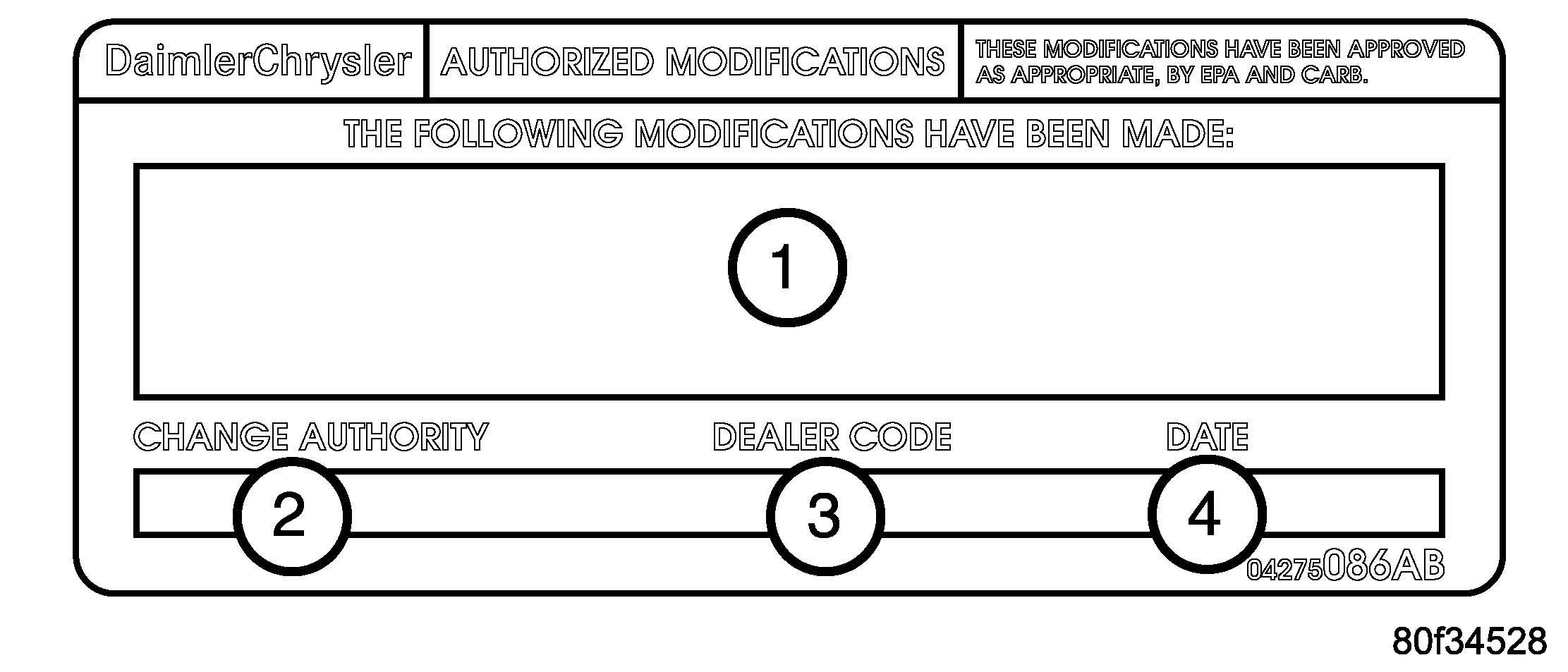
- Type the necessary information on the “Authorized Modification Label” p/n 04275086AB and attach near the VECI label (Fig. 1).
Fig. 1 AUTHORIZED MODIFICATION LABEL
1 – POWERTRAIN CONTROL MODULE P/N (INSERT P/N) USED
2 – CHANGE AUTHORITY: TSB XX-XXX-XX
3 – DEALER CODE: XXXXX
4 – DATE: XX-XX-XX
REPAIR PROCEDURE – USING THE INTERNET TO RETRIEVE THE FLASH FILE:
NOTE: The latest released version of the StarSCAN software must be installed on the StarSCAN tool before the “Using The Internet To Retrieve The Flash File” repair procedure can be performed.
NOTE: The StarSCAN diagnostic scan tool fully supports Internet connectivity. However, in order to take advantage of this feature you must first configure the StarSCAN for your dealership’s network. For instruction on setting up your StarSCAN for the dealer’s network; refer to the StarSCAN Quick Start Networking Guide available on the www.dcctools.com website under the “download center”.
NOTE: Make sure the StarSCAN is configured to the dealership’s network before proceeding.
NOTE: If this flash process is interrupted/aborted, the flash should be restarted.
- Connect the CH9404 StarSCAN vehicle cable to the StarSCAN and the vehicle.
- Connect the CH9410 StarSCAN ethernet cable to the StarSCAN and the dealer’s network drop (optional).
- Retrieve the old PCM part number. Using the StarSCAN at the “Home” screen:
- If the StarSCAN is connected to the dealer’s network drop and the vehicle, proceed to Step #5. If the StarSCAN is not connected to the dealer’s network drop and the vehicle, proceed to Step #9
- select “Browse for new file”.
- Select the appropriate calibration.
- Select “Download to Scantool”.
- Select “Close” after the download is complete. Proceed to Step #10.
- Download the flash file from the Internet to the StarSCAN. Using the StarSCAN at the “Home” screen:
- Select “Flash Download”.
- Select “Enter information manually”. Press the “Next” button and follow the onscreen instructions.
- Select the appropriate calibration.
- Select “Download to Scantool”.
- Select “Close” after the download is complete.
- Connect the CH9404 StarSCAN vehicle cable to the StarSCAN and the vehicle (if notalready connected).
- Open the hood, install a battery charger and verify that charging rate providesapproximately 13.5 volts.
- Download the file from StarSCAN to the vehicle. Using StarSCAN at the “Home”screen:
- Verify that the PCM part number has updated. Using the StarSCAN at the “Home”screen:
NOTE: Due to the PCM programming procedure, a DTC may be set in other modules.
(TCM, BCM, MIC, SKREEM, etc.) within the vehicle, if so equipped. Some DTC’s may cause the MIL to illuminate. From the “Home” Screen select “System View”. Then select “All DTCs”. Press “Clear All Stored DTCs” if there are any DTCs shown on the list.
NOTE: The following step is required by law.
- Type the necessary information on the “Authorized Modification Label” p/n 04275086AB and attach near the VECI label (Fig. 1).
REPAIR PROCEDURE – USING SOFTWARE UPDATE CD TO RETRIEVE THE FLASH FILE:
NOTE: Before flashing this module, make sure the StarSCAN is operating at the latest level and this is the latest flash file available from the StarSCAN update CD. To determine the latest StarSCAN software version level available refer to www.dcctools.com website under the “Latest News” link.
NOTE: If this flash process is interrupted/aborted, the flash should be restarted.
NOTE: For detailed information on the operation of the StarSCAN, refer to the Quick Reference documentation provided in the StarSCAN documentation kit. In addition, more recent information may also be available at the www.dcctools.com website. Look under “Training Aids” and also under “Download Center > Frequently Asked Questions” for more help.
- Retrieve the old PCM part number. Using the StarSCAN at the “Home” screen:
- Select “ECU View”
- Touch the screen to highlight the PCM in the list of modules.
- Record the “Part Number”, displayed on the “ECU Overview” screen, for laterreference.
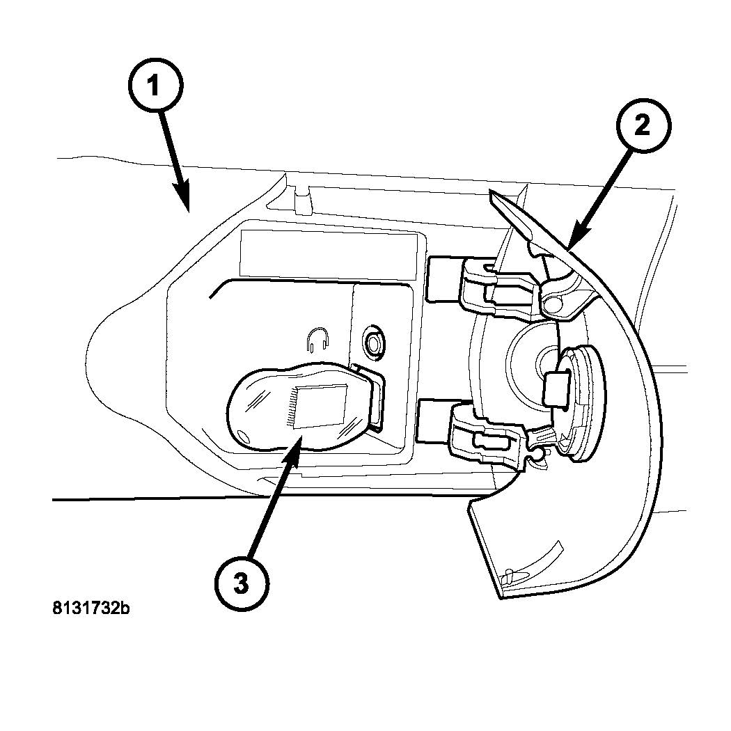
- Insert the USB Key, into the USB port on the TechCONNECT or equivalent PC (Fig 2).
Fig. 2 USB KEY AND TECHCONNECT PC
1 – TechCONNECT PC
2 – ACCESS DOOR (ON FRONT OF TechCONNECT PC)
3 – USB KEY IN THE TechCONNECT PC USB PORT
- Insert the StarSCAN Software Update CD into the TechCONNECT or equivalent PC.
The StarSCAN Software Update CD will start automatically. a. Select “Controller Flash”.
- Follow the on screen instructions.
- At the “Select the type of information you wish to enter.” screen:
- If the old “Part Number” was recorded in Step #1, proceed to Step #5.
- If the old “Part Number” is not known, proceed to Step #6.
- Select “Enter part number”.
- Follow the on screen instructions. Enter the “Part Number” (use capital letters)recorded in Step #1 when prompted to do so. Follow the on screen instructions. Select “Next” after each step . Select “Finish” after completing the last step.
- Proceed to Step #7.
- Select “Enter YME Information”.
- Follow the on screen instructions. Select “Next” after each step. Select “Finish” aftercompleting the last step.
- Proceed to Step #7.
- Using the mouse highlight the appropriate “Calibration”
- Select “Save to USB”
- Follow the on screen instructions. Select “Next”#after each step . Select “Finish”after completing the last step.
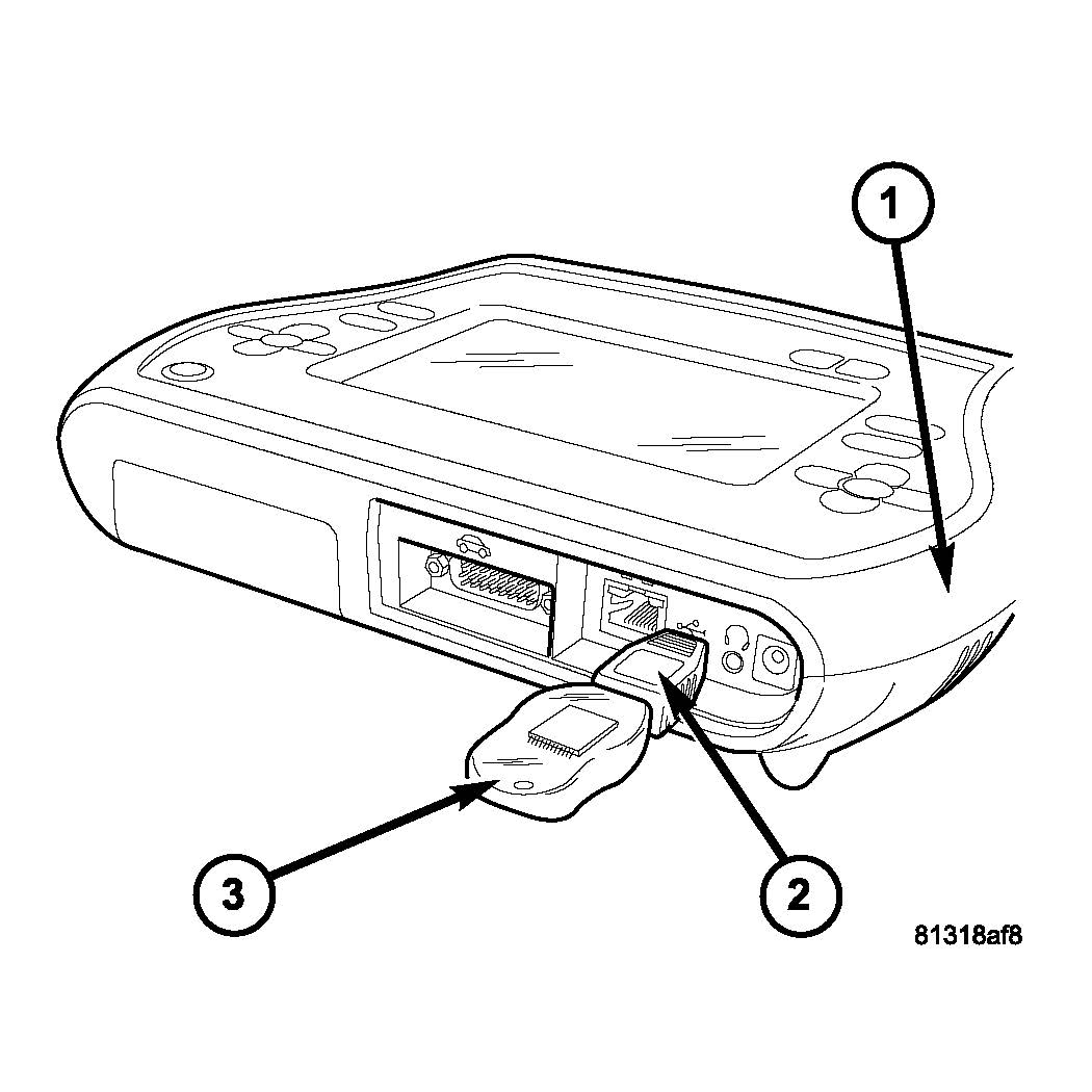
- With the StarSCAN powered OFF, connect the USB Key and Gender Changer to the StarSCAN USB port ( 3).
Fig. 3 USB KEY, GENDER CHANGER, AND StarSCAN TOOL
1 – StarSCAN TOOL
2 – GENDER CHANGER
3 – USB KEY
- Open the hood, install a battery charger and verify the battery state is above 12.5 volts.
- Connect the StarSCAN to the vehicle.
- Power ON the StarSCAN.
- Download the file from the USB key to the StarSCAN. Using the StarSCAN at the“Home” screen:
- Select “Flash Download”
- Select “Use USB device”
- Follow the on screen instructions. Select “Next”#after each step . Select “Finish”after completing the last step.
- At the “Flash File List” screen, highlight the appropriate PCM “Calibration”
- Select “Download to Scantool”
- When the download is complete, select “Close”
- Download the file from the StarSCAN to the vehicle. Using the StarSCAN at the“Home” screen:
- Verify that the PCM part number has updated. Using the StarSCAN at the “Home”screen:
NOTE: Due to the PCM programming procedure, a DTC may be set in other modules.
(TCM, BCM, MIC, SKREEM, etc.) within the vehicle, if so equipped. Some DTC’s may cause the MIL to illuminate. From the “Home” Screen select “System View”. Then select “All DTCs”. Press “Clear All Stored DTCs” if there are any DTCs shown on the list.
NOTE: The following step is required by law.
- Type the necessary information on the “Authorized Modification Label” p/n 04275086AB and attach near the VECI label (Fig. 1).
POLICY:
Reimbursable within the provisions of the warranty.
TIME ALLOWANCE:
| Labor Operation No: | Description | Amount |
|---|---|---|
| 08-19-43-91 | Reprogram Powertrain Control Module | 0.8 Hrs. |
FAILURE CODE:
| FM | Flash Module | |
 Loading...
Chrysler J2534 Application Overview
Flash Availability – J2534/Pass Thru Device
Vehicle to Diagnostic Tool Reference Chart


