| “This site contains affiliate links for which OEMDTC may be compensated” |
NUMBER: 23-013-15
GROUP: Body
DATE: April 16, 2015
THIS SERVICE BULLETIN IS ALSO BEING RELEASED AS RAPID RESPONSE TRANSMITTAL (RRT) 15-035. ALL APPLICABLE UN-SOLD RRT VIN’s HAVE BEEN LOADED. TO VERIFY THAT THIS RRT SERVICE ACTION IS APPLICABLE TO THE UN-SOLD VEHICLE, USE VIP OR PERFORM A VIN SEARCH IN TECHCONNECT. FOR VEHICLES NOT INCLUDED IN THE RRT VIN LIST, APPLICATION OF THIS SERVICE BULLETIN TO SOLD UNITS IS BASED UPON THE CUSTOMER EXPERIENCING THE SYMPTOM/CONDITIONS. ALL REPAIRS ARE REIMBURSABLE WITHIN THE PROVISIONS OF WARRANTY.
SUBJECT:
Power Rear Liftgate Intermittently Will Not Open
OVERVIEW:
This bulletin involves verifying power liftgate release operation and if necessary, replacing the rear liftgate latch.
MODELS:
NOTE: This bulletin applies to vehicles built on or after October 17, 2014 (MDH 1017XX) and on or before October 29, 2014 (MDH 1029XX) equipped with power liftgate (sales code JRC).
SYMPTOM/CONDITION:
The rear liftgate intermittently will not open. A clicking noise may be heard when standing behind the vehicle as latch tries to release.
DIAGNOSIS:
If the vehicle VIN is listed in VIP or your RRT VIN list, perform the repair.
PARTS REQUIRED:
| Qty. | Part No. | Description |
|---|---|---|
| 1 (AR) | 04589581AG | Latch, Liftgate Release |
REPAIR PROCEDURE:
- Is the vehicle in Ship Mode?
- Yes >>> Proceed to Step #2.
- No >>> Proceed to Step #3.
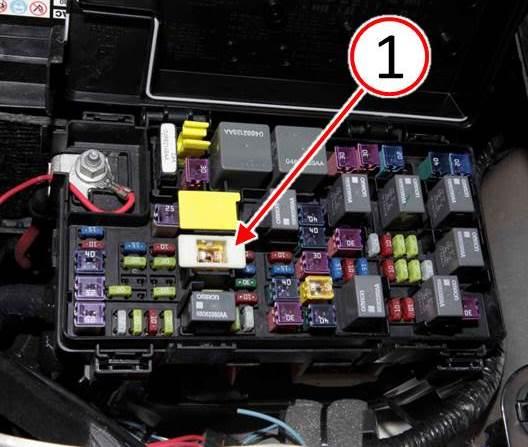
- Press the Ignition-Off Draw Fuse (1) down fully inserting the fuse into the Power Distribution Center (PDC) to take the vehicle out of “Ship Mode” (Fig. 1).
Fig. 1 Ignition-Off Draw Fuse
1 – Ignition-Off Draw Fuse
- Using the Frequency Operated Button Integrated Key (FOBIK), open and close the liftgate 10 times without pause. Did the liftgate fail to open during any of the cycles? a. Yes>>> Continue with the repair procedure Step #4.
- No>>> This RRT has been completed, use LOP (23-41-25-97) to close the active RRT.
NOTE: If the liftgate latch fails to release and liftgate cannot be opened, the latch can be released manually through the access opening. Refer to DealerConnect/TechConnect Service Information section 23 – Body> Decklid/Hatch/Liftgate/Tailgate> Latch> Removal for instructions to manually release the latch.
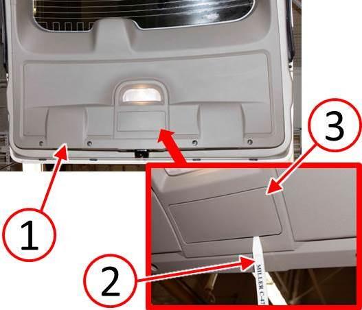
- Open the liftgate (1) (Fig. 2).
- Disconnect and isolate the negative battery cable.
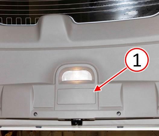
- Using trim stick or equivalent (2), remove the trim panel access panel (3) (Fig. 2).
Fig. 2 Remove Liftgate Access Panel
1 – Liftgate
2 – Trim Stick
3 – Access Panel
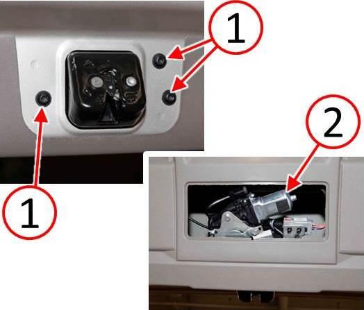
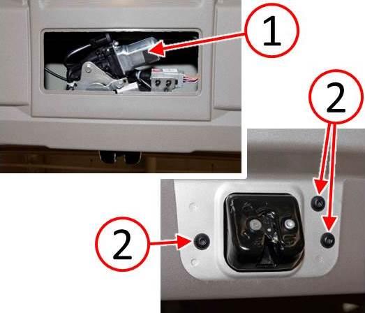
- Remove the three screws (1) that secure the liftgate latch to the liftgate (Fig. 3).
- Remove the latch (2) from the liftgate (Fig. 3).
Fig. 3 Remove Liftgate latch
1 – Liftgate Latch Screws
2 – Liftgate Latch
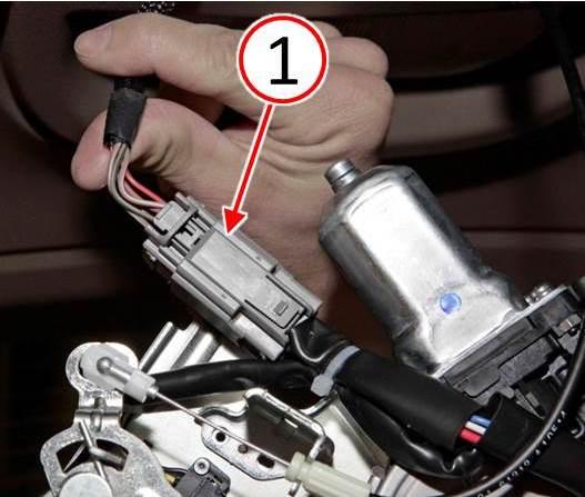
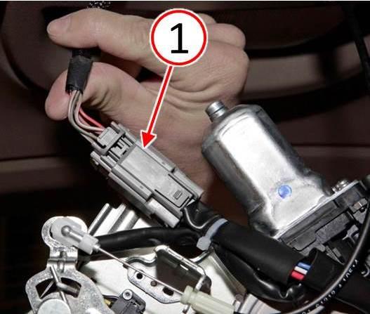
- Disconnect the electrical harness (1) from the liftgate latch (Fig. 4).
Fig. 4 Disconnect Liftgate latch Electrical Harness
1 – Electrical Harness Connector
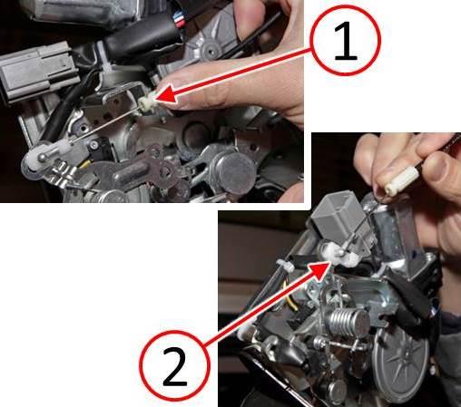
- Remove the latch cable ferrule (1) from the latch (Fig. 5).
- Disconnect the latch cable end (2) from the latch (Fig. 5).
Fig. 5 Disconnect Liftgate latch Cable
1 – Latch Cable Ferrule
2 – Latch Cable End
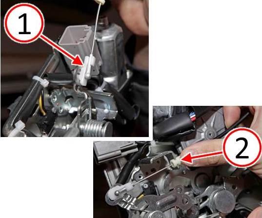
- Connect the latch cable end (1) to the liftgate latch (Fig. 6).
- Install the latch cable furrule (2) to the liftgate latch (Fig. 6).
Fig. 6 Connect Liftgate Latch Cable
1 – Latch Cable End
2 – Latch Cable Ferrule
- Connect the electrical harness (1) to the liftgate latch (Fig. 7).
Fig. 7 Connect Liftgate latch Electrical Harness
1 – Electrical Harness Connector
- Position the liftgate latch (1) to the to the inside of the liftgate (Fig. 8).
- Install the three screws (2) that secure the liftgate latch to the liftgate and tighten the screws to 11 Nm (95 in. lbs.) (Fig. 8).
Fig. 8 Install Liftgate Latch
1 – Liftgate Latch
2 – Liftgate Latch Screws
- Install the liftgate latch access panel (1) to the liftgate trim panel (Fig. 9).
Fig. 9 Install Liftgate Access Panel
1 – Access Panel
- Connect the negative battery cable.
- Verify liftgate operation.
- If necessary, place the vehicle back into “Ship Mode” by lifting the Ignition-Off Draw Fuse (1) up disconnecting the fuse from the Power Distribution Center (PDC) (Fig. 1).
POLICY:
Reimbursable within the provisions of the warranty.
TIME ALLOWANCE:
| Labor Operation No: | Description | Skill Category | Amount |
|---|---|---|---|
| 23-41-25-97 | Latch, Liftgate Release – Inspect Only (1 – Semi-Skilled) | 6- Electrical and Body Systems | 0.2 Hrs. |
| 23-41-25-98 | Latch, Liftgate Release – Inspect and Replace (1 – Semi-Skilled) | 6- Electrical and Body Systems | 0.3 Hrs. |
FAILURE CODE:
| ZZ | Service Action |
 Loading...
 Town and Country