| “This site contains affiliate links for which OEMDTC may be compensated” |
NUMBER: 02-005-15 REV. B
GROUP: Front Suspension
DATE: April 30, 2015
THIS BULLETIN SUPERSEDES SERVICE BULLETIN 02-005-15 REV. A, DATED APRIL 23, 2015, WHICH SHOULD BE REMOVED FROM YOUR FILES. ALL REVISIONS ARE HIGHLIGHTED WITH **ASTERISKS** AND INCLUDE BECOMING A RAPID RESPONSE TRANSMITTAL (RRT) AND BULLETIN APPLICABILITY DATE RANGE HAS CHANGED.
**THIS SERVICE BULLETIN IS ALSO BEING RELEASED AS RAPID RESPONSE TRANSMITTAL (RRT) 15-046. ALL APPLICABLE SOLD AND UN-SOLD RRT VIN’s HAVE BEEN LOADED. TO VERIFY THAT THIS RRT SERVICE ACTION IS APPLICABLE TO THE VEHICLE, USE VIP OR PERFORM A VIN SEARCH IN TECHCONNECT. ALL REPAIRS ARE REIMBURSABLE WITHIN THE PROVISIONS OF WARRANTY.**
SUBJECT:
Front End Popping Noise While Driving Over Bumps
OVERVIEW:
This bulletin involves using structural adhesive to bond the front upper shock absorber brackets to the carbon fiber structure.
MODELS:
| 2015 | (4C) | Alfa 4C |
NOTE: **This bulletin applies to vehicles built on or after July 9, 2014 (MDH 0709XX) and on or before December 12, 2014 (MDH 1212XX).**
SYMPTOM/CONDITION:
The customer may describe a popping noise in the front of the vehicle while driving over bumps at low speeds.
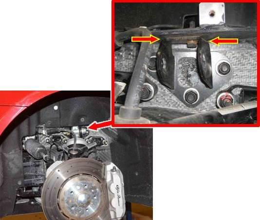
The popping noise may be caused by movement between the front upper shock absorber mount bracket and the carbon fiber structure in the area shown in (Fig. 1).
Fig. 1 Noise From Contact Area Between Shock Absorber Bracket And Structure
DIAGNOSIS:
If a customer’s VIN is listed in VIP or your RRT VIN list, perform the repair. For all other customers that describe the symptom/condition listed above, perform the Repair Procedure.
PARTS REQUIRED:
| Qty. | Part No. | Description |
| 2 | 68236515AA | Nut M14 Shock Absorber Upper |
| 2 | 68236514AA | BOLT, Hex Head M14 Shock Absorber Upper |
| 2 | 68236516AA | Nut M12 Shock Absorber Lower |
| 2 | 68236483AA | BOLT, Hex Head M12 Shock Absorber Lower |
| 6 | 68243347AA | Nut M10 Shock Absorber Bracket |
| 2 | 68236473AA | BOLT, Hex Head M8 Shock Absorber Bracket |
| 1 (AR) | 04318031 | MOPAR Lock & Seal Adhesive or Material Standard CC75 equivalent |
| 1 (AR) | NPN | LORD Fusor® 2098 Structural Adhesive = 6.59 oz (195 mL)
OR 3M® 07333 Structural Adhesive = 6.75 oz (200 mL) |
NOTE: Each tube of MOPAR Lock & Seal Adhesive will service approximately 6 vehicles.
NOTE: 1 cartridge of LORD Fusor® 2098 or 3M® 07333 structural adhesive will service approximately 1 vehicle.
NOTE: For LORD Fusor technical support or to find a local distributor, please call +1 800 234 FUSOR (3876).
SPECIAL TOOLS/EQUIPMENT REQUIRED:
| NPN | Fusor® 313 Adhesive Dispensing Gun |
| NPN | 3M® B26T200 Albion Adhesive Dispensing Gun |
NOTE: The adhesive dispensing gun is a non-reimbursable shop tool.
REPAIR PROCEDURE:
- Raise and support the vehicle. Refer to the detailed service procedures available in DealerCONNECT> TechCONNECT under: Service Info> 04 – Vehicle Quick Reference> Hoisting> Standard Procedure.
- Remove the front wheel assemblies. Refer to the detailed service procedures available in DealerCONNECT> TechCONNECT under: Service Info> 22 – Tires and Wheels> Removal and Installation.
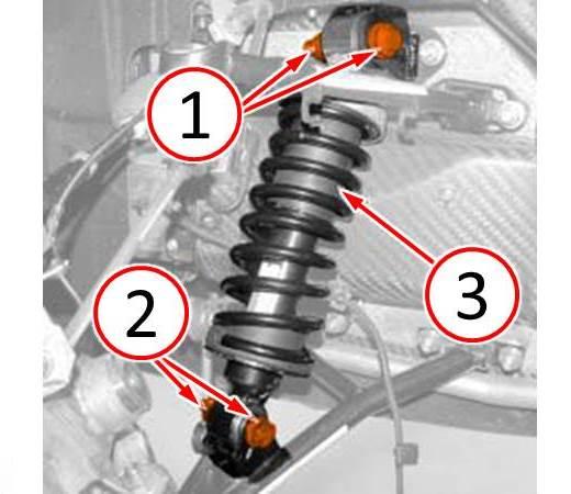
- Remove the upper fasteners (1) from the shock absorber (Fig. 2).
- Remove the lower fasteners (2) from the shock absorber (Fig. 2).
- Reposition the shock absorber (3) for access to the upper shock absorber bracket (Fig. 2).
Fig. 2 Remove Fasteners And Reposition Shock Absorber
1 – Shock Absorber Upper Fasteners
2 – Shock Absorber Lower Fasteners
3 – Shock Absorber
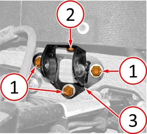
- Remove and discard the nuts (1) from the shock absorber bracket (Fig. 3).
- Remove and discard the bolt (2) from the shock absorber bracket (Fig. 3).
- Remove the shock absorber bracket (3) from the vehicle (Fig. 3).
Fig. 3 Remove Shock Absorber Upper Bracket
1 – Shock Absorber Bracket Fastener Nuts
2 – Shock Absorber Bracket Fastener Bolt
3 – Shock Absorber Bracket
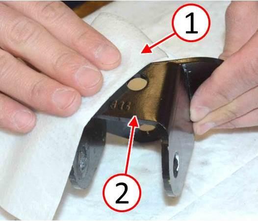
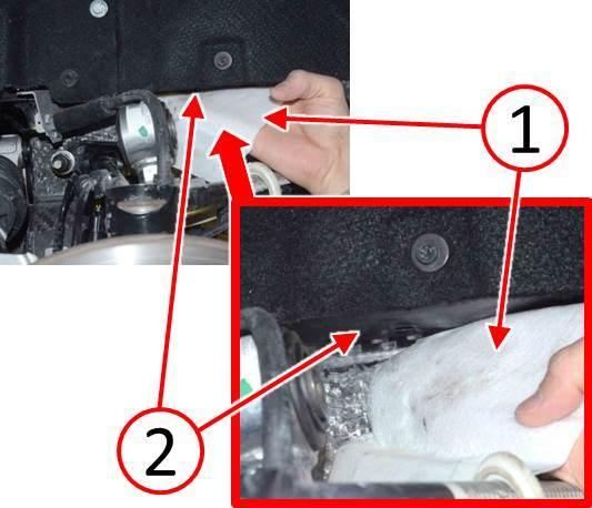
- Using a clean cloth and isopropyl alcohol (1), thoroughly clean the shock absorber bracket top surface (2) (Fig. 4).
Fig. 4 Clean Shock Absorber Bracket Top Surface
1 – Alcohol Wipe
2 – Shock Absorber Bracket Top Surface
- Using a clean cloth and isopropyl alcohol (1), thoroughly clean the carbon fiber vehicle structure at the shock absorber bracket contact surface (Fig. 5).
Fig. 5 Clean Contact Surface Of Structure To Shock Absorber Bracket
1 – Alcohol Wipe
2 – Carbon Fiber Structure Shock Absorber Bracket Contact Surface
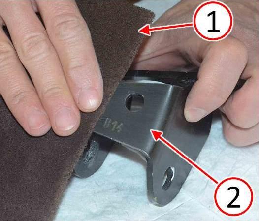
- Using an abrasive pad (1), scuff the top surface (2) of the shock absorber bracket to improve adhesive bond ( 6).
- Using an abrasive pad, also scuff the carbon fiber vehicle structure at the bracketcontact surface to improve adhesive bond.
Fig. 6 Scuff Top Surface Of Shock Absorber Bracket With Abrasive Pad
1 – Abrasive Pad
2 – Shock Absorber Bracket Top Surface
- Insert the two-component structural adhesive cartridge into the dispensing gun.
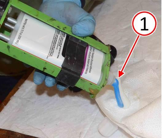
- Squeeze a small amount of the two-component adhesive from each side of the cartridge (1) ( 7). This will level the plungers and ensure that the adhesive is coming out of both sides of the adhesive cartridge.
Fig. 7 Purge Air From Adhesive Cartridge
1 – Purge Air From Adhesive Cartridge
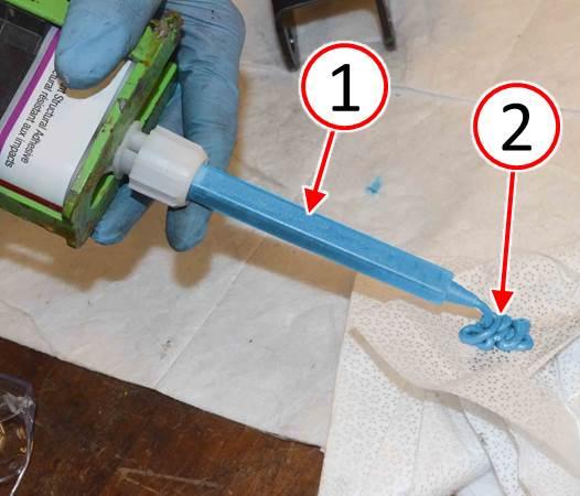
- Attach the mixing tip (1) to the adhesive cartridge then dispense a small amount of material (2), approximately the length of the mixing tip, to verify that the adhesive is evenly mixed in the mixing tip (Fig. 8).
Fig. 8 Attach Mixing Tip To Adhesive Cartridge And Ensure Proper Mix
1 – Adhesive Cartridge Mixing Tip
2 – Verify Even Two-Component Adhesive Mixing
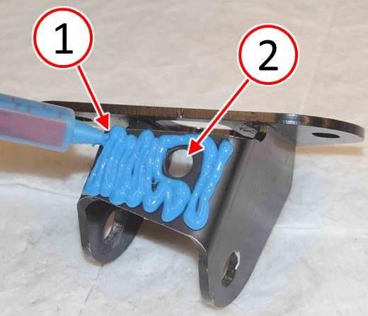
NOTE: The structural adhesive (1) must not cover the fastener hole (2) (Fig. 9).
- Apply structural adhesive (1) to the top surface of the shock absorber bracket. Be sure to avoid the fastener hole (2) (Fig. 9).
Fig. 9 Apply Adhesive to Shock Bracket Top Surface
1 – Apply Adhesive 2 – M8 Bolt Hole
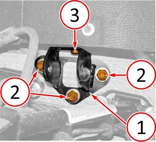
- Install the shock absorber bracket (1) to the vehicle structure (Fig. 10).
- Install by hand but do not fully tighten the NEW M10 nuts (2) (Fig. 10).
- Apply MOPAR lock & seal adhesive or equivalent to the NEW M8 bolt threads and install by hand but do not fully tighten the NEW M8 bolt (3) (Fig. 10).
NOTE: Ensure the shock absorber bracket is held firmly against the vehicle structure mounting surfaces (no gap visible) before tightening the fasteners.
- Tighten the M10 nuts (2) to 55 N·m (41 ft. lbs.) + 45 degrees (Fig. 10).
- Tighten the M8 bolt (3) to 20 N·m (15 ft. lbs.) (Fig. 10).
Fig. 10 Install Shock Absorber Bracket Using New Fasteners
1 – Shock Absorber Bracket
2 – Shock Absorber Bracket Fastener Nuts
3 – Shock Absorber Bracket Fastener Bolt
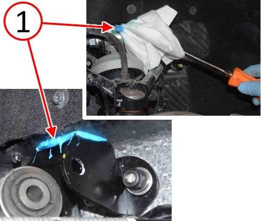
- Remove any excess structural adhesive (1) that may have squeezed out between the shock absorber bracket and the vehicle structure (Fig. 11).
Fig. 11 Remove Excess Adheasive
1 – Excess Adhesive
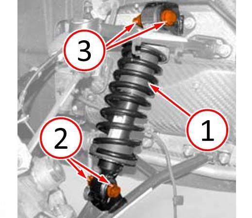
- Place the shock absorber (1) into the proper mounting position (Fig. 12).
- Install by hand but do not fully tighten the NEW lower M12 shock absorber fasteners (2) (Fig. 12).
- Install by hand but do not fully tighten the NEW upper M14 shock absorber fasteners (3) (Fig. 12).
- Place the suspension at curb height before tightening the upper and lower shockabsorber fasteners.
- Tighten the lower M12 nut (2) to 120 N·m (89 ft. lbs.) (Fig. 12).
- Tighten the upper M14 nut (3) to 150 N·m (110 ft. lbs.) (Fig. 12).
Fig. 12 Install Shock Absorber Using New Fasteners
1 – Shock Absorber
2 – Shock Absorber Lower Fasteners
3 – Shock Absorber Upper Fasteners
- Install the front wheel assemblies. Refer to the detailed service procedures available in DealerCONNECT> TechCONNECT under: Service Info> 22 – Tires and Wheels> Removal and Installation.
CAUTION: The vehicle must be parked in an area where the ambient temperature is at or above 72 degrees F (22 degrees C) and structural adhesive must be allowed to cure for one hour before driving the vehicle on the road.
- Lower the vehicle and park for 1 hour at 72 degrees F (22 degrees C) before driving.
- Verify the popping noise has been eliminated.
POLICY:
Reimbursable within the provisions of the warranty.
TIME ALLOWANCE:
| Labor Operation No: | Description | Skill Category | Amount |
| 02-15-17-90 | Bond Right And Left Front Upper Shock Absorber Brackets To Carbon Fiber Structure (1 – Semi-Skilled) | 4 – Chassis Systems | 1.5 Hrs. |
FAILURE CODE:
| ZZ | Service Action |
PART REIMBURSEMENT DETAIL:
| Part No: | Description |
| NPN | MOPAR Lock & Seal Adhesive |
| NPN | LORD Fusor® 2098 Structural Adhesive = 6.59 oz (195 mL)
OR 3M® 07333 Structural Adhesive = 6.75 oz (200 mL) |
NOTE: This part number is for reimbursement only and will need to be claimed for 1/6 of Dealer Net of Part No. 04318031 or it will be rejected.
NOTE: This part number is for reimbursement only and will need to be claimed for the value of LORD Fusor® 2098 or 3M® 07333 or it will be rejected. If this is a non-MOPAR part or product, a copy of the invoice showing the purchase of the non-MOPAR part or product needs to be attached to the reimbursement claim.
 Loading...
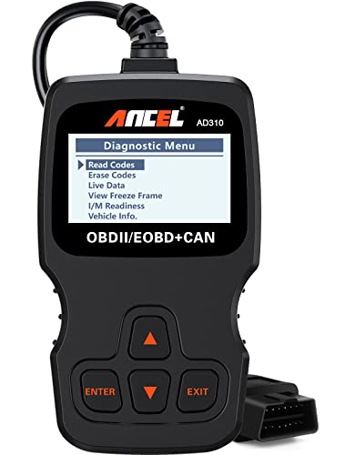
- CEL Doctor: The ANCEL AD310 is one of the best-selling OBD II scanners on the market and is recommended by Scotty Kilmer, a YouTuber and auto mechanic. It can easily determine the cause of the check engine light coming on, quickly read and clear diagnostic trouble codes, read live data & hard memory data, view freeze frame, I/M monitor readiness and collect vehicle information. Instead of taking car to mechanic shop, you can use it to check the trouble code and show code definition by yourself.
- Sturdy and Compact: Equipped with a 2.5 foot cable made of very thick, flexible insulation. It is important to have a sturdy scanner as it can easily fall to the ground when working in a car. The AD310 OBD2 scanner is a well-constructed mechanic tool with a sleek design. It weighs 12 ounces and measures 8.9 x 6.9 x 1.4 inches. Thanks to its compact design and light weight, transporting the device is not a problem. The buttons are clearly labelled and the screen is large and displays results clearly.
- Accurate Fast and Easy to Use: The AD310 scanner can help you or your mechanic understand if your car is in good condition, provides exceptionally accurate and fast results, reads and clears engine trouble codes in seconds. If you want to find out the cause of the check engine light, this device will let you know immediately and fix the problem right away without any car knowledge. No need for batteries or a charger, get power directly from the OBDII Data Link Connector in your vehicle.
- OBDII Protocols and Car Compatibility: Many cheap scan tools do not really support all OBD2 protocols. This is not the case with the AD310 scanner as it can support all OBDII protocols such as KWP2000, J1850 VPW, ISO9141, J1850 PWM and CAN. This device also has extensive vehicle compatibility with 1996 US-based, 2000 EU-based and Asian cars, light trucks, SUVs, as well as newer OBD2 and CAN vehicles both domestic and foreign. Check compatibility with your vehicle model before purchasing.
- Home Necessity and Worthy to Own: This is an excellent code reader to travel or home with as it weighs less and it is compact in design. You can easily slide it in your backpack as you head to the garage, or put it on the dashboard, this will be a great fit for you. The AD310 is not only portable, but also accurate and fast in performance. Moreover, it covers various car brands and is suitable for people who just need a code reader to check their car.
- [Pro OBD2 Scanner] - BlueDriver is the easiest way to scan and understand your vehicle like a professional mechanic. Read and clear your car’s trouble codes and check engine light.
- [Read & Clear All The Codes] - BlueDriver's enhanced vehicle diagnostics gives you access to information normally available only to mechanics on their OBD2 scan tools. Now you can read and clear ABS, Airbag, SRS, TPMS codes, and many more.
- [Get The Right Fix & View Live Data] - Much more than a car code reader, BlueDriver is a diagnostic tool. You’ll get unlimited repair reports with possible causes and fixes, plus real-time health monitoring while you drive with the live data feature.
- [Wireless & Bluetooth Enabled] - Say goodbye to wires. BlueDriver connects with Bluetooth via your phone/tablet to a sensor that plugs into your car's OBDII port. Get all of the capabilities of an expensive code reader & scan tool without any annoying wires.
- [User-Friendly App and Repair Videos] - BlueDriver gives you more ways to scan and fix your vehicle. Our iOS & Android app connects you to a large database of repair videos with step-by-step directions of repairs.
- [Vehicle CEL Doctor] The NT301 obd2 scanner enables you to read DTCs, access to I/M readiness status, figure out the root reason of check engine light or MIL turned on, monitor sensors test, read live data and retrieve VIN of your vehicle. The fault code only can be cleared after repair finished by NT301, as like all the obd2 code readers' working principle
- [Accuracy & Streams] Live data graphing and logging. Accurately read error codes for most Worldwide cars, SUVs, light trucks and 12V diesels equipped with Obd2. Graphing live vehicle sensors data allows you to focus on any suspicious data and trend.
- [Worthy to Own] Recommended by most professional mechanics on Youtube. Codes analysis and Printer compatible. Unique PATENTED design, 2.8" color screen and 1-year seller assurance with EXCLUSIVE tech and service team. Plug & Play, no need to update before using. Available to windows system. NOT support ios and Mac
- [S-mog Check Helper] Read/Erase and I/M readiness hotkeys make it easy to use the car computer reader right out of the package. Red-Yellow-Green Leds and build-in speaker indicate the readiness status for confident e-missions test
- [Home Necessity] Open to global customers. No battery required, NT301 obd scanner is charged directly from the 16pin DLC in your vehicle. It is recommended as a necessity in your toolbox and great choice for Home and Autoshop Mechanics. This scanner for car only supports to read the fault code of engine system, not support ABS or SRS
- WIDE COMPATIBILITY – Trusted by YouTube Star Scotty Kilmer. The AD410 OBD2 Scanner supports all 16PIN vehicles that comply with the OBDII protocol, including KWP2000, ISO9141, J1850 VPW, J1850 PWM, and CAN. This OBD2 code scanner compatible with 1996 US-based, 2000 EU-based and Asian cars, light trucks, SUVs, as well as newer OBD2 and CAN vehicles. Multilingual support (English, German, French, Spanish, etc.), this car code reader is ideal for international users. Check compatibility with your vehicle model before purchasing. !!! Powered directly from your vehicle's OBDII connector, this diagnostic tool doesn' t need a battery or charger.
- CRITICAL FUNCTIONALITY – Quickly Read & Clear Fault Codes. The AD410 obd2 scanner diagnostic tool quickly reads and clears stored emissions-related codes, pending codes, and provides code definitions. With over 42,000 built-in DTC lookups, you can easily identify faults without the need for Google searches. Reset the MIL, check monitor readiness before smog tests, and understand your vehicle's health before costly repairs. !!! Note: Fault codes can be cleared after resolving the underlying issue, the code reader itself does not have a reset function.
- ENHANCED OBDII DIAGNOSTICS – Comprehensive System Testing. This engine obd2 scanner diagnostic tool offers advanced diagnostics, including testing of O2 sensors and EVAP systems. Perform a leak test on your vehicle's EVAP system and monitor the fuel tank's integrity. The O2 sensor test helps fine-tune the air/fuel mixture, improving fuel efficiency and reducing emissions—saving you money at the pump and reducing your car's environmental impact. !!! Note: The AD410 is only an engine code reader, it DOESN'T support other systems such as ABS, SRS, Transmission and others.
- QVGA DISPLAY & NEW UI – Easy-to-Use, User-Friendly Interface. The AD410 scanner for car boasts a 2.4 TFT true-color LCD display (262K) for clear, easy-to-read results. With an intuitive UI design, you can quickly access OBDII diagnostics, I/M readiness checks, DTC search, and setup options. No need to read a manual—this user-friendly auto diagnostic code scanner is perfect for beginners, mechanic and seasoned users alike.
- DIAGNOSTIC REPORTS & FREE LIFETIME UPDATES. The AD410 car scanner reader allows you to review, save, or print detailed diagnostic trouble code reports. Plus, with lifetime free software updates, you’ll always have the latest features and bug fixes. Simply download the updates from the ANCEL website and follow the easy on-screen installation instructions. (Note: update is not necessary, the AD410 code reader can be directly inserted into the OBDII interface of the car to use, if it doesn't work, then consider updating the device.) The ANCEL website provides the latest product user manual, which can be downloaded and viewed at any time.
- Professional OBD2 Scanner Diagnostic Tool with Powerful Functions:OBD2 scanner code reader feature built-in 35901 OBD2 DTCs lookup library, As professional car scanner, the obd2 scanner diagnostic tool will help you to determine the cause of the engine light,read I/M readiness, Read & clear codes, turn off engine light or MIL, view freeze frame, retrieve vehicle VIN, battery voltage test, live data stream, onboard monitoring mode, and perform component testing etc
- OBD2 Scanner Built-in 35,901 DTC Lookup: The OBD2 scanner car code reader built-in 35,901 DTCs, the old model obd2 scanner diagnostic tool usually only have 3,000-10,000.the OBD2 Scanner of DTC library covers tens of thousands detailed fault code definitions that will quickly determine the fault cause and catch potential problems before they cost you a fortune. Besides, you don't need to google the meaning of each fault code.If you are looking to replace or upgrade an existing car code reader, this code reader is an excellent option.
- OBD2 Diagnostic Scanner Tool Compatible with 98% Vehicles And Multiple Languages: The code reader OBD2 scanner for cars is designed to be compatible with most vehicles manufactured after 1996 US-Based, 2000 EU-Based and Asian cars. If your car has a 16-pin OBD2 port and was produced within the specified timeline, it should be compatible with the code reader and the obd2 scanner diagnostic tool support for 10 languages: English, French, Spanish, German, Chinese, Russian, Italian, Japanese, Portuguese, Dutch, which make it easy to use for people from different countries.
- Car Scanner Diagnostic offers Convenient Data Printing:The code reader for car offers advanced features such as live data and DTC replay combined with printing function, Connect the OBD2 scanner to your computer to easily print fault data, empowering you to prevent random charges at car repair shops and save valuable time and money. Additionally, WEJOWE offer lifetime free upgrades for the device, ensuring you always have access to the latest features and improvements.
- Super Compact & What You Will Get: The OBD2 scanner tool is easy to carrying and storage,With each package, you will receive a canvas storage bag for convenient storage and a Type-C cable to connect to your computer.And Car Scanner Diagnostic offers Convenient Data Printing:The code reader for car offers advanced features such as live data and DTC replay combined with printing function, Connect the OBD2 scanner to your computer to easily print fault data, empowering you to prevent random charges at car repair shops and save valuable time and money.
- Multi-Functions - It's a practical multi-function OBD2 code reader which helps you determine the cause of the check engine light coming on, quickly read and remove diagnostic trouble codes, read live data & hard memory data, view freeze frame, I/M monitor readiness and collect vehicle information. Instead of taking car to mechanic shop, you can use it to check the trouble code and show code definition by yourself. Wide Compatibility - Supports 9 protocols compatible with most 1996 US-Based, 2000 EU-Based and Asian cars, light trucks, SUVs, as well as newer OBD2 and CAN vehicles both domestic and foreign. Check compatibility with your vehicle model before purchasing. It can also be used for some motorcycle OBD2 system diagnosis. (Note: an additional specific adapter cable is needed. not included with this device) 2.8" LCD Display & Multi-language - Designed with a clear 2.8" LCD screen (128 x 64 pixels) - white backlight and contrast adjustment. No need any battery or charger, OBD reader gets the power directly from your vehicle through the OBDII Data Link Connector. It also supports 6 languages - English,German, Dutch, Spanish, French and Italian. This scanner is enjoyed and highly recommended by the customers worldwide. Compact Design & Easy to Use - It weighs about 12 ounces and measures 6 x 2.75 x 0.9 inches. Equiped with a 2.5 feet long heavy duty cable and the standard 16-PIN OBD connector. 6 buttons for quick operation. The plug and play design makes it user-friendly. Even if you don't have much technical knowledge, you can operate it without any hassle. "Accurate & Fast - Different with other similar scanners, the MP69033 scanner use the brand new ARM micro processor to make sure the ultra high accuracy and fast speed. With the excellent performance of the micro processor, the detailed real-time engine data can be detected and displayed on the screen in seconds. Get codes, fix the problem and turn off the CEL. If you just need a code reader to check your car, it's definitely an affordable and reliable tool.
- 🔥【On-Screen DTC Definition, Save Time & Easy To Use】Autel MS309 OBD2 code reader with UPGRADED CHIP to retrive and clear generic(P0, P2, P3 and U0), manufacturer-specific(P1, P3 and U1) and pending codes, and display DTCs(Diagnostic Trouble Codes) meanings under the codes based on the built-in database(more than 3000 codes). Don't need to spend much time to search meanings on the internet. This advanced plug-and-play MS309 scanner saves you time - a must-have obd2 scanner for each car owner.
- 🔥【Retrieve Freeze Frame Data &Vehicle info】The more specific the information available, the clearer the problem. The OBD2 scanner MS309 can retrieve freeze frame data, including important engine parameters like RPM, fuel pressure, fuel trim, engine coolant temperature, etc. Also it can retrieve Vehicle Information such as VIN number, Calibration ID(s), Calibration Verification Nos. (CVNs), etc, which is useful to check whether the ECU matches when you are buying a used car.
- 🔥【Read Codes & Clear Codes】Knowing the codes in advance will brace you for the repair cost estimate so that you won't be fooled and get overcharged by the repair shop.This Autel MaxiScan MS309 obd2 scanner scans OBD2-compliant vehicle Diagnostic Trouble Codes (DTCs) in seconds to pinpoint emission-related issues. The little guy can do many basic but necessary works: read/clear codes, view DTC definition, turn off check engine light, check I/M Readiness status, retrieve freeze frame data and vehicle info.
- 🔥【Turn Off Check Engine Light】When your car detects an emission related problem, Check Engine Light will be turned on. Do you want to spend hundreds of dollars to turn off this light every time, maybe it's just a gas cap that's not tightened or needs to change bad parts like spark plugs and ignition coils? With Autel MS309 scan tool, you can read code to quickly find out why the check engine light is on and reset it.
- 🔥【Ready For Annual Smog Check】If the OBD II Readiness Monitors on your car are not “Ready”, your car may fail the smog check. MS309 OBD2 scanner can retrieve I/M Readiness status to check the monitors like misfire monitor, fuel system monitor, comprehensive components monitor, catalyst monitor, O2 sensors, EVAP, etc, to help your car ready pass the annual smog check. That way you won't waste time and money on a failed smoke check.
- 【TURN OFF CEL】 This AL319 car diagnostic tool supports Reading DTCs, displaying Live Data, Freeze Frame & I/M Readiness etc to figure out the root cause of the Check Engine Light (CEL) and turning it off, to help you detect any potential problems, and to avoid excessive costs for unnecessary repairs.
- 【EXTENSIVE APPLICATION】 Autel AL319 Compatible with 7 languages (English, French, Spanish, etc.) and various post-1996 OBD II protocol vehicles (Toyota, Nissan, Honda, Ford, etc.), this OBD II scanner provides accurate and fast diagnosis for worldwide car owners.
- 【FOR END USER & DIYERS】 This error code reader AL319 is “plug and play” and comes with an easy interface. Even if you’re not familiar with vehicle repair, you can quickly take control of this obd2 scanner, and get the information you want.
- 【USER-FRIENDLY DESIGN】 This check engine code reader features a patented One-Click I/M Readiness, TFT color display, built-in speaker, LED Indicator etc. The cable is long enough without being too long and getting in the way. No batteries are needed.
- 【HIGH-QUALITY SERVICES】 12 months warranty from the date of purchase and lifetime free update are offered by this Automobile OBDII scan tool. Welcome to contact us via Q&A, email, or hotline, and our after-sale-service team for technical support.
- Full OBDII Modes Scanner for Car: As professional car scanner, ZM201 has all the OBD2 functions you need. Read & clear codes, turn off engine light or MIL, view freeze frame, read I/M readiness, retrieve vehicle VIN, battery voltage test, live data stream (with graphing display), built-in 35901 DTCs, O2 sensor test, onboard monitoring mode, and perform component testing etc.
- Enhanced OBD2 Scanner Diagnostic Tool: Live data and DTC replay combined with printing function, you can connect it to a computer for fault data printing, prevent auto repair shops from charging randomly, save money and time. ZM201 obd scanner also comes with free-lifetime software updates, ensuring you always have the latest features and improvements.
- 35,901 DTC Lookup: ZM201 car code reader built-in 35,901 DTCs, the old model obd2 usually only have 3,000-10,000. So the ZM201 car scanner has a huge advantage, which means that this obd2 scanner can better help diagnose and solve your vehicle faults. This is a great option if you want to replace or upgrade an existing car scanner.
- Compatible with 98% Vehicles: ZM201 OBD2 scanner for car is compatible with most cars after 1996(USA)/2002(EU)/2008(Asia). If your car has an OBD2 port (16Pin), and the production time meets the above timeline, then your vehicle is compatible. But it is not compatible with new energy vehicles, hybrid vehicles, and models that do not comply with the OBD2 protocol.
- Convenient Shortcut Functions: The addition of shortcut keys enhances the user experience. Pressing F1 enables you to quickly retrieve trouble codes, while F2 provides instant access to I/M readiness information. We've also introduced left and right navigation buttons (the previous model had only up and down buttons), making operation even more convenient.
- Full Systems Diagnostic: ANCEL DS160 offers comprehensive and in-depth diagnostics for all available modules. This includes the main system of engine, ABS (Brake), SRS (Airbag), transmission, ESP, SAS, audio control, air conditioning control, PCM, and more.This enables you to detect issues early on and make informed decisions for achieving optimal performance.
- 30+ F-ree Reset Services: The DS160, compatible with kia, hyundai and genesis, offers over 30 special functions like injector coding, ABS Bleeding, gearbox learn, throttle learn, battery matching, SAS, oil, AdBlue reset, etc. These functions simplify maintenance and help extend vehicle longevity. Note: the reset functions vary based on the car model and year, provide your vehicle details for assistance. Get more reset functions under the "diagnose-vehicle brand-system-special functions".
- Advanced Bidirectional Control: This scan tool allows you to send commands directly to the car's E-C-U and components for active testing. It performs specific tests on various systems, including windows, mirrors, door, injectors, brakes, wipers, cooling fan, headlights, horn, fuel pump, and A/C clutch. This feature helps assess the condition of car actuators, making it easier to determine if repairs are necessary, ensuring accurate and efficient diagnostics.
- E-C-U Off Line Coding: It enables you to customize your car setting for your engine control unit, such as refresh hidden features and disable unwanted features for energy saving or better driving. Note: it does not support online coding.
- Lifetime F-ree WiFi Update: In contrast to other OBD2 scanners on the market that demand users to pay for updates,Our tool comes with over 30 reset functions and lifetime f-ree updates.This not only saves you more but also provides you with peace of mind. You can be assured that you are always using the most up-to-date version of the tool. This leads to more accurate diagnoses and enhanced overall performance.
Last update on 2025-05-08 / Affiliate links / Images from Amazon Product Advertising API
This product presentation was made with AAWP plugin.
