| “This site contains affiliate links for which OEMDTC may be compensated” |
NUMBER: 13-002-15
GROUP: Frames & Bumpers
DATE: April 29, 2015
THIS SERVICE BULLETIN IS ALSO BEING RELEASED AS RAPID RESPONSE TRANSMITTAL (RRT) 15-042. ALL APPLICABLE SOLD AND UN-SOLD RRT VIN’s HAVE BEEN LOADED. TO VERIFY THAT THIS RRT SERVICE ACTION IS APPLICABLE TO THE VEHICLE, USE VIP OR PERFORM A VIN SEARCH IN TECHCONNECT. ALL REPAIRS ARE REIMBURSABLE WITHIN THE PROVISIONS OF WARRANTY.
SUBJECT:
Trailer Tow Package Not Installed On Vehicle
OVERVIEW:
This bulletin involves installing a MOPAR accessory trailer hitch and related wiring.
MODELS:
| 2015 | (VF) | Ram Pro Master Pro Master |
NOTE: This bulletin applies to vehicles built on or after October 9, 2014 (MDH 1009XX) and on or before October 31, 2014 (MDH 1031XX) equipped with Mopar Trailer Tow Group (sales code AHT).
SYMPTOM/CONDITION:
The customer may describe the trailer hitch missing from a vehicle ordered with a trailer hitch.
DIAGNOSIS:
If a customer’s VIN is listed in VIP or your RRT VIN list, perform the repair. For all other customers that are missing the trailer tow package on vehicles with sales code AHT, perform the Repair Procedure.
PARTS REQUIRED:
| Qty. | Part No. | Description |
|---|---|---|
| 1 | 82213897AB | Class IV Trailer Hitch |
| 1 | 82213930AC | Trailer Tow Prep Harness |
| 1 | 82208454AB | Ram Receiver Plug Receiver Plug |
REPAIR PROCEDURE:
- Remove the rear bumper fascia. Refer to the detailed service procedures available in DealerCONNECT> TechCONNECT under: Service Info> 13 – Frame and Bumpers> Bumpers> FASCIA, Rear> Removal.
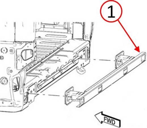
- Remove and discard the rear bumper reinforcement. Refer to the detailed service procedures available in DealerCONNECT> TechCONNECT under: Service Info> 13 Frame and Bumpers> Bumpers> REINFORCEMENT, Bumper, Rear> Removal.
Fig. 1 Rear Bumper Reinforcement
1 – Bumper Reinforcement
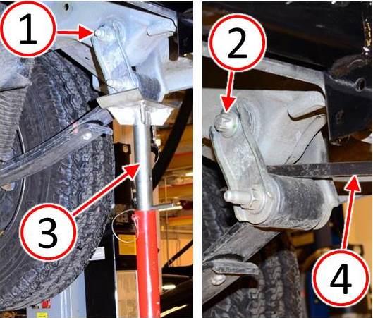
NOTE: If the upper spring shackle bolt threaded end (1) is pointing inboard (toward the spare tire) it will be necessary for trailer hitch clearance to turn the upper shackle bolt around so that the bolt head (2) is inboard and bolt threaded end is pointing outboard (Fig. 2).
- Inspect upper spring shackle bolts. Is the threaded end of the bolt facing inboard toward the spare tire?
- YES>>> Continue with Step #4.
- NO>>> Proceed to Step #5.
- If the right and/or left side upper spring shackle bolt must be turned around, perform the following steps:
- Lift and support the vehicle. Refer to the detailed service procedures available inDealerCONNECT> TechCONNECT under: Service Info> 04 – Vehicle Quick Reference> Hoisting> Standard Procedure.
- Support the rear spring shackle with an appropriate stand (3) (Fig. 2). A pry bar (4) may be necessary to position the spring shackle for removal and installation of the upper spring shackle bolt (Fig. 2).
- Loosen the lower spring shackle bolt to ease upper bolt removal/installation.
- Remove the upper spring shackle nut and bolt (1) (Fig. 2).
- Turn the upper spring shackle bolt around and reinstall so that the bolt head (2) isfacing inboard toward spare tire (Fig. 2).
- Install the upper spring shackle nut but do not tighten.
- Lower the vehicle to curb height.
- Tighten both the upper and lower spring shackle nuts to 170 N·m (125 ft lbs) torque.
Fig. 2 Spring Shackle Bolts
1 – Bolt Threaded End
2 – Bolt Head
3 – Stand
4 – Pry Bar
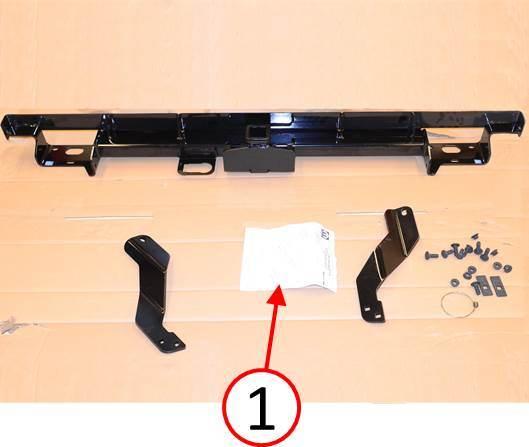
- Unbox the trailer hitch kit (Fig. 3).
NOTE: Leave the bumper fascia off the vehicle until the trailer wiring harness has been fully installed.
- For hitch installation, follow the MOPAR trailer hitch installation instructions (1) provided in the trailer hitch kit ( 3). If the installation instruction sheet is missing, a replacement copy may be downloaded from the Star Parts catalog. Refer to group 001A – MOPAR Accessories> 200 – Carriers & Cargo Hauling Accessories> 204 Hitches & Towing. Click on the Hitch Receiver Info link to download/print a replacement installation instruction sheet.
Fig. 3 Trailer Hitch Kit
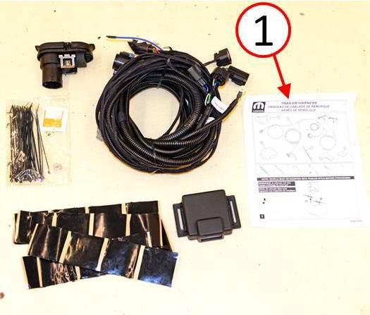
- Unbox the trailer tow wire harness kit (Fig. 4).
- For wire harness installation, follow the MOPAR trailer tow wire harness installation instructions (1) provided in the kit ( 3). If the installation instructions are missing, a replacement copy may be downloaded from the Star Parts catalog. Refer to group 001A – MOPAR Accessories> 200 – Carriers & Cargo Hauling Accessories> 204 Hitches & Towing. Click on the Trailer Tow Wiring Harness Cargo Vans Info link to download/print replacement installation instructions.
Fig. 4 Trailer Wire Harness Kit
1 – Installation Instructions
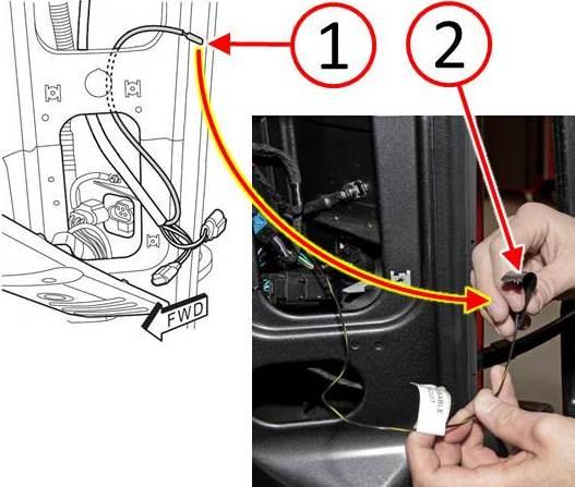
NOTE: The park assist wire (1) is part of the trailer tow wire harness and is located near the right rear passenger side tail lamp when the trailer tow wire harness is installed in the vehicle (Fig. 5).
- If the vehicle is not equipped with park assist, tape the exposed end of the park assist wire (1) with electrical tape (2) so that the wire does not make contact with any metal surface (Fig. 5).
Fig. 5 Park Assist Wire
1 – Park Assist Wire
2 – Electrical Tape
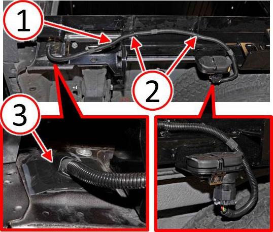
- Secure the trailer tow wire harness (1) to the trailer hitch using cable ties (2) suppliedin the wire harness kit (Fig. 6).
- Seal the trailer tow wire harness grommet exit point by using mastic patches (3) supplied in the wire harness kit (Fig. 6).
Fig. 6 Trailer Wire Harness Routing
1 – Trailer Tow Wire Harness
2 – Cable Ties
3 – Mastic Patches
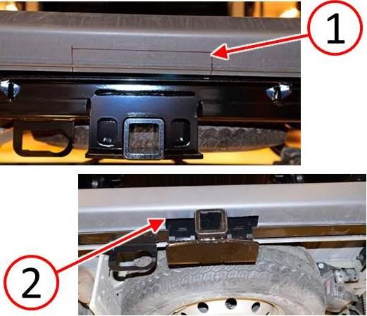
- Following the hitch installation instruction sheet directions, trim the underside of the rear bumper facia (1) as necessary for receiver clearance (2) (Fig. 7).
Fig. 7 Trim Rear Fascia For Receiver Clearance
1 – Scribed Cut Line
2 – Facia Trimmed For Clearance
- Install the rear bumper fascia. Refer to the detailed service procedures available inDealerCONNECT> TechCONNECT under: Service Info> 13 – Frame and Bumpers> Bumpers> FASCIA, Rear> Installation.
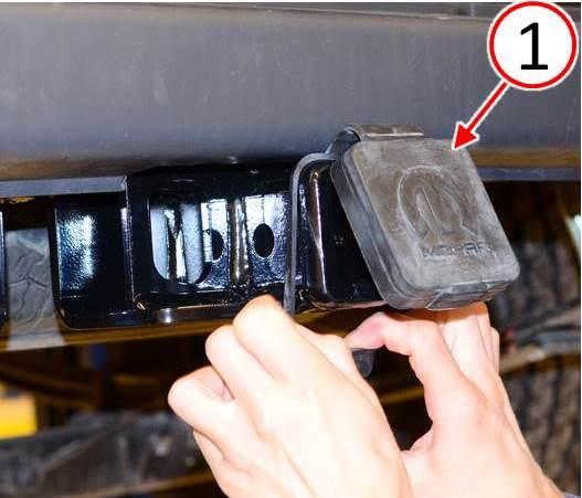
- Install the receiver plug onto the trailer hitch receiver (Fig. 8).
Fig. 8 Receiver Plug
1 – Receiver Plug
- Test all functions of trailer lighting for proper operation.
POLICY:
Reimbursable within the provisions of the warranty.
TIME ALLOWANCE:
| Labor Operation No: | Description | Skill Category | Amount |
|---|---|---|---|
| 23-99-51-90 | Hitch, Trailer Tow And Wiring Kit Install (1 – Semi-Skilled) | 6 – Electrical and Body Systems | 2.9 Hrs. |
FAILURE CODE:
| ZZ | Service Action |
 Loading...
