| “This site contains affiliate links for which OEMDTC may be compensated” |
NUMBER: 05-003-15
GROUP: Brakes
DATE: May 27, 2015
SUBJECT:
Rear Brake Noise
OVERVIEW:
This bulletin involves replacing the rear brake shoes and wheel cylinders.
MODELS:
| 2015 | (VM) | Ram ProMaster City ProMaster City |
NOTE: This bulletin applies to vehicles built on or before December 02, 2014 (MDH 1202XX) equipped with 4-Wheel Anti-Lock Brakes (sales codes BGK).
SYMPTOM/CONDITION:
The customer may describe a rear brake squeak/squeal noise when applying the brakes and/or a pop/click noise when applying and/or releasing the brakes.
DIAGNOSIS:
If the customer describes the symptom/condition, perform the Repair Procedure.
PARTS REQUIRED:
| Qty. | Part No. | Description |
|---|---|---|
| 2 | 68283192AA | Shoe Kit (services one side only) |
| 2 | 68283193AA | Wheel Cylinder |
REPAIR PROCEDURE:
NOTE: Before beginning, Refer to the brake system Warnings and Cautions available in DealerCONNECT> TechCONNECT under: Service Info> 05 Brakes, Base – Warning and Caution.
NOTE: For vehicles without an air outlet in the floor console, proceed to Step #2.
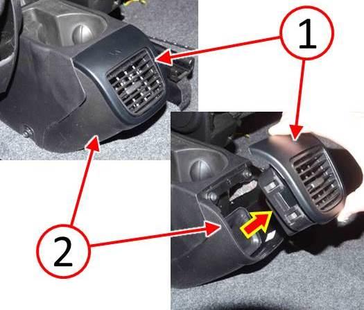
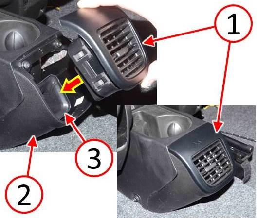
- Use a trim stick or equivalent to release and remove the air outlet (1) from the floor console end cap (2) (Fig. 1).
Fig. 1 Remove Floor Console Air Outlet
1 – Air Outlet
2 – Floor Console End Cap
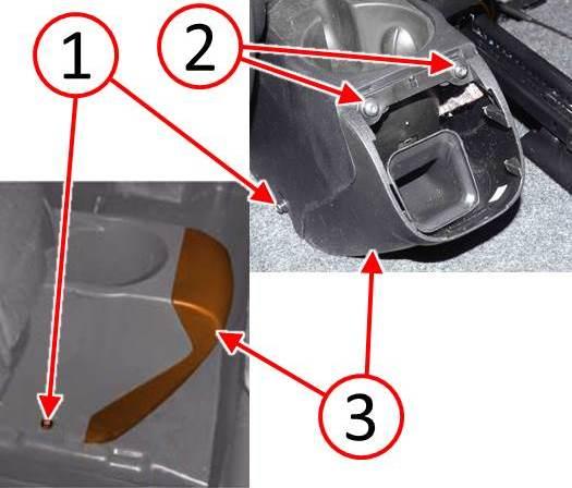
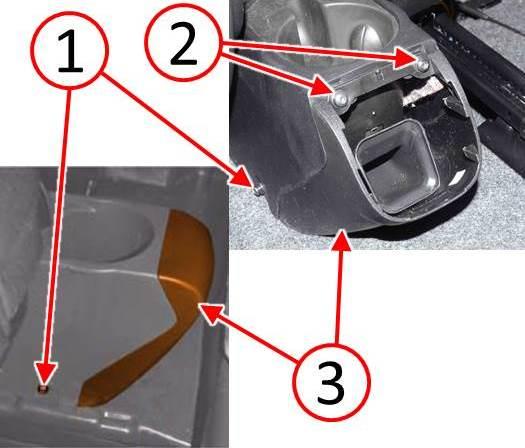
- Vehicle may be equipped with or without an air outlet in the floor console as shown in (Fig. 2). Perform the following applicable steps depending on how vehicle is equipped:
- Without air outlet: Remove the two lower screws (1) from the right and left side of the floor console, then remove the end cap (3) (Fig. 2).
- With air outlet: Remove the two lower screws (1) from the right and left side of the floor console and remove the two upper screws (2), then remove the end cap (3) (Fig. 2).
Fig. 2 Remove Floor Console End Cap
1 – Screws
2 – Floor Console End Cap
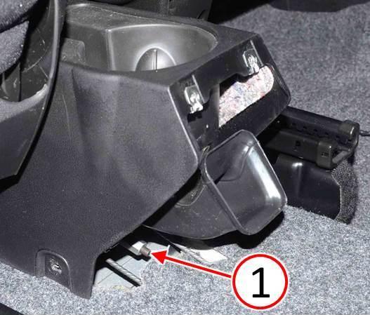
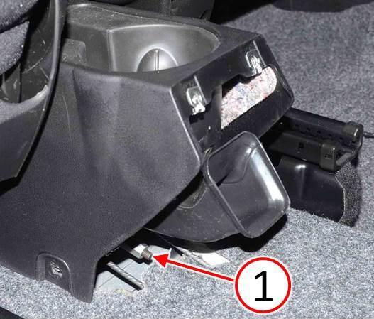
- Take note of the parking brake adjustment nut position, then loosen the nut (1) at least two or three turns to ensure the parking brake cables are completely slack (Fig. 3).
Fig. 3 Loosen Parking Brake Cable
1 – Parking Brake Cable Adjustment Nut
- Raise and support the vehicle. Refer to the detailed service procedures available in DealerCONNECT> TechCONNECT under: Service Info> 04 – Vehicle Quick Reference> Hoisting> Standard Procedure.
- Remove both rear tire and wheel assemblies. Refer to the detailed service procedures available in DealerCONNECT> TechCONNECT under: Service Info> 22 – Tires and Wheels> Removal.
NOTE: Left side brake assembly shown, right side brake assembly similar.
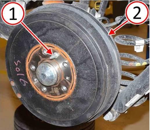
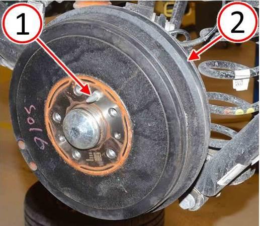
- Remove the brake drum retaining pin (1), then remove the brake drum (2) (Fig. 4).
Fig. 4 Remove Rear Brake Drums
1 – Brake Drum Retaining Pin
2 – Brake Drum
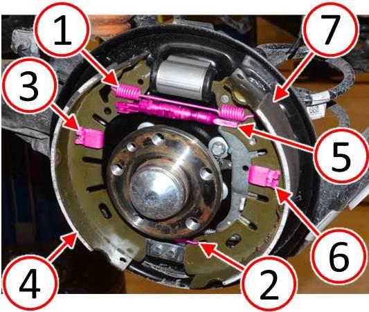
- Remove the upper brake shoe return spring (1) and lower brake shoe return spring (2) (Fig. 5).
- Remove the front-facing brake shoe retaining clip (3) and brake shoe (4) (Fig. 5).
- Remove the brake shoe adjuster (5) ( 5).
- Remove the rear-facing brake shoe retaining clip (6) (Fig. 5).
- Disconnect the park brake cable from the rear-facing brake shoe (7), then remove the brake shoe (Fig. 5).
Fig. 5 Remove Rear Brake Shoes
1 – Upper Brake Shoe Return Spring
2 – Lower Brake Shoe Return Spring
3 – Brake Shoe Retaining Clip
4 – Front-Facing Brake Shoe
5 – Brake Shoe Adjuster
6 – Brake Shoe Retaining Clip
7 – Rear-Facing Brake Shoe
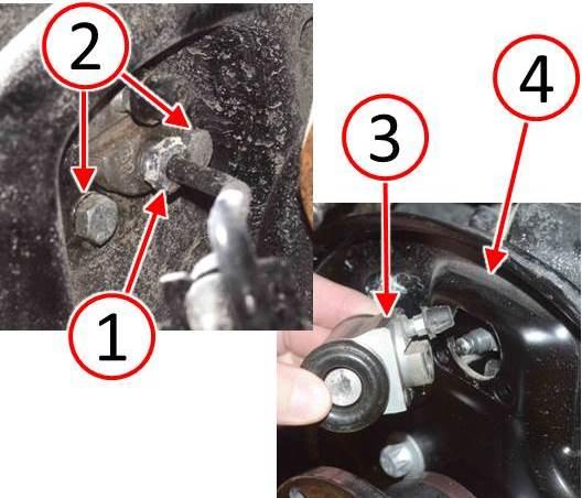
- Disconnect the hydraulic brake tube (1) at the wheel cylinder (Fig. 6).
- Remove the wheel cylinder attaching screws (2) (Fig. 6).
- Remove the wheel cylinder (3) from the backing plate (4) (Fig. 6).
- Install the NEW wheel cylinder (3) to the backing plate (4) (Fig. 6).
- Install the wheel cylinder attaching screws (2) and tighten to 13 N·m (115 in. lbs.) (Fig. 6).
- Hand start the hydraulic brake tube nut (1) into the wheel cylinder and tighten to 17 N·m (150 in. lbs.) (Fig. 6).
Fig. 6 Replace Rear Wheel Cylinders
1 – Hydraulic Brake Tube Nut
2 – Wheel Cylinder Attaching Screws
3 – Wheel Cylinder
4 – Brake Backing Plate
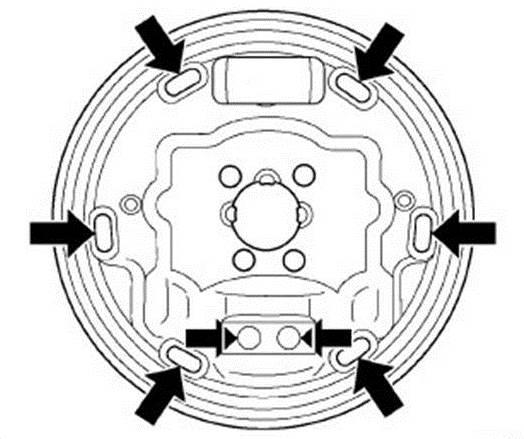
- Lubricate the shoe contact areas on the backing plate and anchor using Mopar® Brake Lubricant or equivalent (Fig. 7).
- Lubricate the brake shoe adjuster screw threads with Mopar® Brake Lubricant orequivalent. Turn the adjuster wheel in until it is completely seated.
Fig. 7 Apply Lubricant To Backing Plate
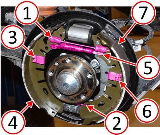
- Connect the park brake cable to the NEW rear-facing brake shoe (7) (Fig. 8).
- Install the NEW rear-facing brake shoe (7) and retaining clip (6) (Fig. 8).
- Install the brake shoe adjuster (5) (Fig. 8).
- Install the NEW front-facing brake shoe (4) and retaining clip (3) (Fig. 8).
- Install the lower brake shoe return spring (2) and upper brake shoe return spring (1) (Fig. 8).
Fig. 8 Install Rear Brake Shoes
1 – Upper Brake Shoe Return Spring
2 – Lower Brake Shoe Return Spring
3 – Brake Shoe Retaining Clip
4 – front-facing Brake Shoe
5 – Brake Shoe Adjuster
6 – Brake Shoe Retaining Clip
7 – rear-facing Brake Shoe
- Turn the brake shoe adjuster to obtain a proper brake shoe to brake drum clearance setting. A slight drag from the brake shoes should be felt while rotating the brake drum.
- Install the brake drum (2), then install the brake drum retaining pin (1). Tighten the pinto 12.5 N·m (110.6 in. lbs.) (Fig. 9).
Fig. 9 Install Rear Brake Drums
1 – Brake Drum Retaining Pin
2 – Brake Drum
- Bleed the wheel cylinders as necessary. Refer to the detailed service procedures available in DealerCONNECT> TechCONNECT under: Service Info> 05 – Brakes/05 Brakes, Base/Standard Procedure.
- Install both rear tire and wheel assemblies. Refer to the detailed service proceduresavailable in DealerCONNECT> TechCONNECT under: Service Info> 22 – Tires and Wheels> Installation.
- Lower the vehicle.
- Properly adjust the parking brake control cable by turning the adjustment nut (1) (Fig. 10). Refer to the detailed service procedures available in DealerCONNECT> TechCONNECT under: Service Info> 05 – Brakes, Base> Parking Brake> CABLE, Parking Brake> Adjustment.
Fig. 10 Adjust Parking Brake Cable
1 – Parking Brake Cable Adjustment Nut
- Vehicle may be equipped with or without an air outlet in the floor console as shown in (Fig. 11). Perform the following applicable steps depending on how vehicle is equipped:
- Without air outlet: Install the end cap (3), then install the two lower screws (1) to the right and left side of the floor console (Fig. 11).
- With air outlet: Install the end cap (3), then install the two upper screws (2) and the two lower screws (1) to the right and left side of the floor console (Fig. 11).
Fig. 11 Install Floor Console End Cap
1 – Screws
2 – Floor Console End Cap
NOTE: For vehicles equipped without an air outlet in the floor console, proceed to Step #33.
NOTE: Ensure the air outlet (1) aligns properly with the air duct (3) during installation (Fig. 12).
- Install the air outlet (1) to the floor console end cap (2) (Fig. 12).
Fig. 12 Install Floor Console Air Outlet
1 – Air Outlet
2 – Floor Console End Cap
3 – Air Duct
- Test the service brakes applying in both forward and reverse directions to ensure the brakes operate properly.
- Test the parking brake for proper operation.
POLICY:
Reimbursable within the provisions of the warranty.
TIME ALLOWANCE:
| Labor Operation No: | Description | Skill Category | Amount |
|---|---|---|---|
| 05-90-50-96 | Replace Rear Brake Shoes And Wheel Cylinders (2 – Skilled) | 4 – Chassis Systems | 1.2 Hrs. |
FAILURE CODE:
| ZZ | Service Action |
 Loading...
