| “This site contains affiliate links for which OEMDTC may be compensated” |
NHTSA Campaign Number: 15V879
Component(s): ELECTRICAL SYSTEM , INTERIOR LIGHTING
Potential Number of Units Affected: 389,252
Manufacturer: Chrysler (FCA US LLC)
SUMMARY:
Chrysler (FCA US LLC) is recalling certain model year 2011-2013 Dodge
 Durango and Jeep
 Grand Cherokee vehicles manufactured December 3, 2009, to September 1, 2012.
In the affected vehicles, the wiring for the vanity lamp in the sun visor may short circuit, after having been remedied for a prior recall for the vanity lamp wiring.
This recall is also addressing certain vehicles that have not been remedied under that prior recall.
CONSEQUENCE:
The vanity lamp wiring may short, increasing the risk of a vehicle fire.
REMEDY:
Chrysler will notify owners, and dealer will install clearance for sun visor wiring, protection from sharp edges, and replace the sun visor, free of charge.
The recall began on July 28, 2016.
Owners may contact Chrysler customer service at 1-800-853-1403.
Chrysler ’s number for this recall is R71.
NOTES:
Owners may also contact the National Highway Traffic Safety Administration Vehicle Safety Hotline at 1-888-327-4236 (TTY 1-800-424-9153), or go to www.safercar.gov.
Check if your Vehicle has a Recall
Dealer Service Instructions for:
Revised August 2016
Safety Recall R71 / NHTSA 15V-879 Sun Visor Wiring
NOTE: The model year information section has been revised.
NOTE: This recall applies only to the above vehicles equipped with a sun visor vanity light (sales code GNC) built through September 01, 2012 (MDH 090100).
Subject
The sun visor vanity lamp wiring on about 388,600 of the above vehicles may experience a high resistance short after a service repair to the sun visor, headliner or while gaining access above the headliner. This may result in an inoperative vanity lamp and an increased risk of fire.
Repair
The sun visor wiring must be inspected on all involved vehicles that may have had an improper service procedure. Any damaged sun visor vanity lamp wiring will be repaired. Also, the sun visors will be replaced, the sheet metal will be modified and wire guides will be installed to reroute sun visor vanity lamp wiring to prevent wiring damage.
Parts Information
| Part Number | Description |
|---|---|
| CBXDP361AB | Sun Visor Wire Guide Package |
| Each package contains the following components: | |
| Quantity | Description |
| 1 | Guide, sun visor wire (right side) |
| 1 | Guide, sun visor wire (left side) |
Each dealer to whom vehicles in the recall were assigned will receive enough Sun Visor Wire Guide Packages to service about 15% of those vehicles.
| Part Number | Description |
|---|---|
| CBXZR711AA | Sun Visor Assembly (Grey WK /WD) |
| CBXZR712AA | Sun Visor Assembly (Beige (WK only) |
| 68065586AA | Tape, Abrasion
NOTE: One roll of tape will repair 40 vehicles. |
| 68303542AB | Tape, Patch (5”x 3”) (50 patch quantity)
NOTE: This is a roll with 50 tape patches. One roll can repair up to 10 vehicles (6 patches per vehicles without a sunroof or a single pane sunroof/8 patches per vehicle with a dual pane sunroof). |
| 68303542AA | Tape, Patch (5”x 3”) (1,500 patch quantity)
NOTE: The above part number is a bulk roll of 1,500 tape patches and can repair up to 300 vehicles. This is the same tape patches as in 68303542AB only in a larger quantity roll and is probably already in your dealer parts inventory. Check your dealership parts inventory before ordering additional tape patches. |
| 04443633 | Primer, Corrosion Resistant (MS 90082)
NOTE: One can of primer will repair 50 vehicles. |
| Part Number | Description |
| 1MZ82HL1AC | Cover, Single Visor Screw (Beige) |
| 1MZ82HDAAC | Cover, Single Visor Screw (Grey) |
NOTE: The above covers should only be ordered if the original part was damaged during the repair process.
The following special tools are required to perform this repair:
| wiTECH VCI Pod Kit |
| Laptop Computer |
| wiTECH Software |
| Support, Headliner Opening |
| Templates, Magnets, and Carbide Burr |
Service Procedure
CAUTION: Wash your hands thoroughly before performing this service procedure to avoid staining the headliner.
NOTE: Six tape patches are required for vehicles without a sunroof / seven tape patches per vehicle equipped with a sunroof
- If equipped, open sunroof shade.
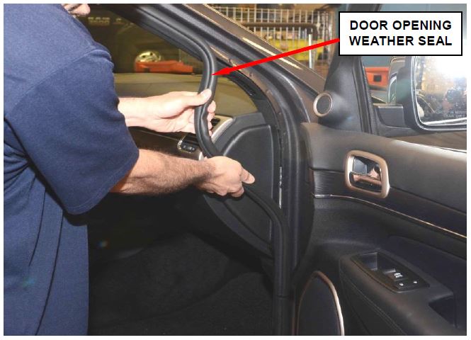
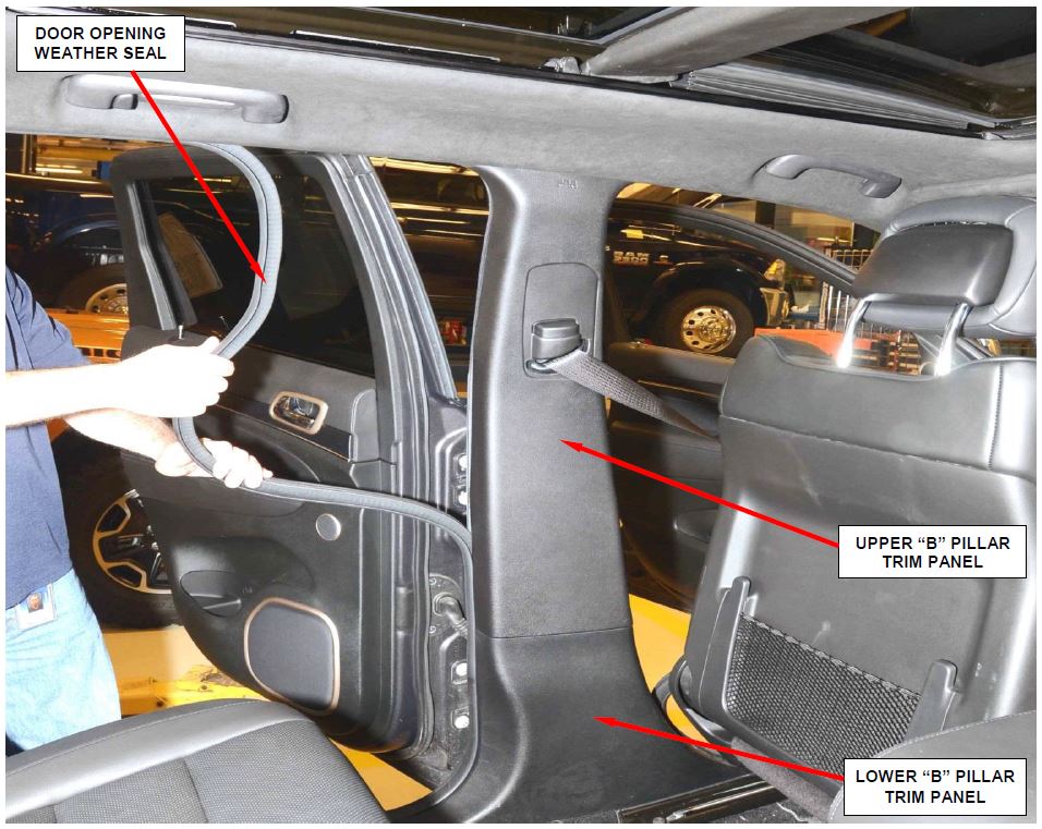
Figure 1 – Door Opening Weather Seal
- Move both front seats to the full rear position.
- Remove and save the right and left side front door opening sill plates.
- Remove and save the right and left side front door weather seals (Figure 1).
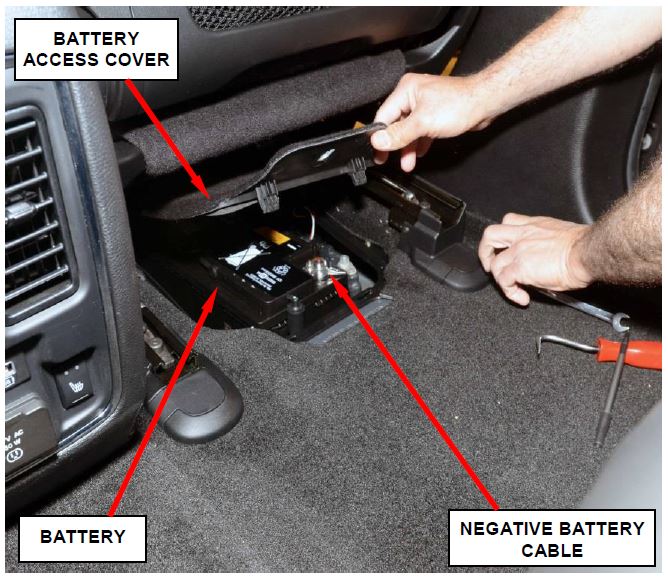
- Disconnect the negative battery cable located under the passenger seat (Figure 2).
CAUTION: After disconnecting the negative battery cable, wait two minutes before continuing with this service procedure.
Figure 2 – Battery Location
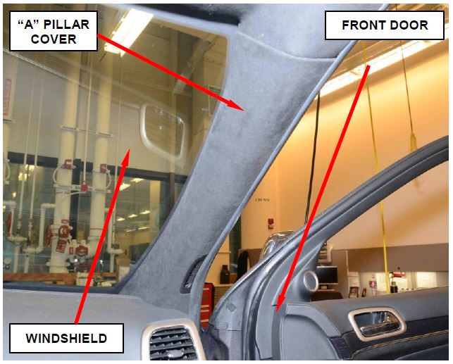
- Remove and save the right and left side “A” pillar covers (Figure 3).
CAUTION: Use extreme care when disconnecting the “A” pillar cover tether.
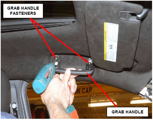
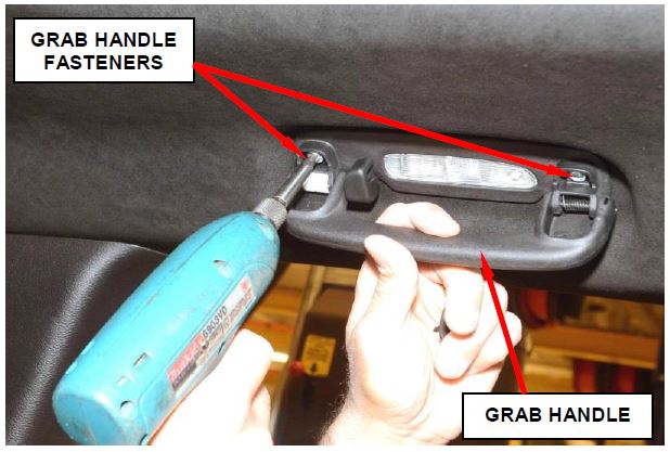
- Remove and save the right and left side front overhead grab handles (Figure 4).
- Temporarily connect the negative battery cable to the battery.
Figure 3 – “A” Pillar Cover (right side shown)
- Move both front seats to the full forward position.
- Disconnect the negative battery cable.
CAUTION: After disconnecting the negative battery cable, wait two minutes before continuing with this service procedure.
- Remove and save the right and left side rear door opening sill plates.
Figure 4 – Front Overhead Grab Handle
Figure 5 – Rear Door Weather Seal and “B” Pillar Panels
- Remove and save the right and left side rear door weather seals (Figure 5).
- Remove and save the right and left side upper and lower “B” pillar trim panels (Figure 5).
- Remove and save the right and left side rear overhead grab handles (Figure 6).
Figure 6 – Rear Overhead Grab Handle
- Temporarily connect the negative battery cable to the battery.
- Move the seats to the full rear position.
- Disconnect the negative battery cable.
CAUTION: After disconnecting the negative battery cable, wait two minutes before continuing with this service procedure.
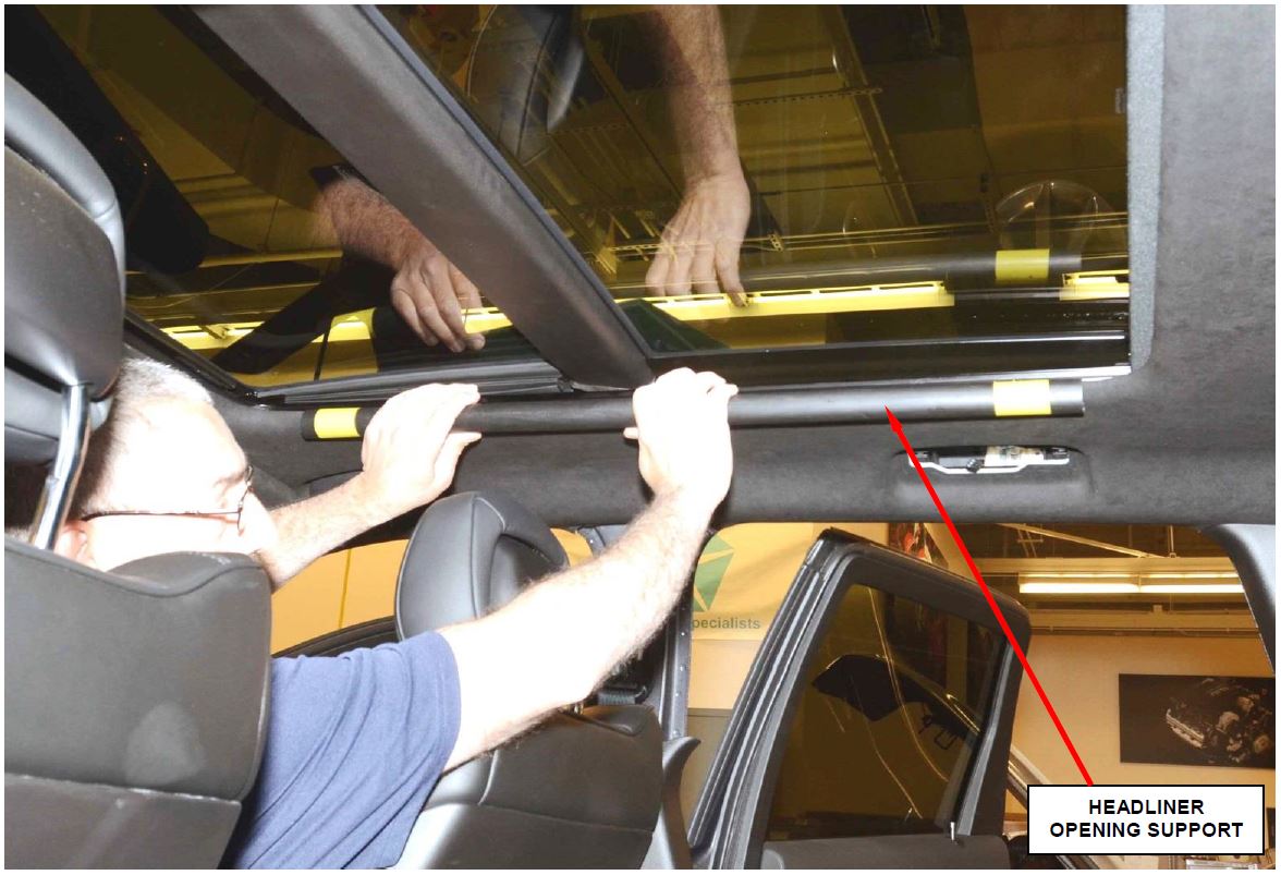
- For vehicles equipped with a dual pane sunroof, install right and left side headliner opening supports (Special Tool 2021400230) (Figure 7).
Figure 7 – Headliner Stiffener Tubes (Dual Pane Sunroof Only)
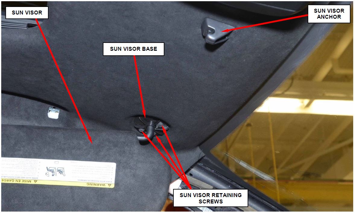
- Remove and save the right and left side sun visor screw covers (Figure 8).
- Adjust the front seats to support the headliner with the headrest in the highest position.
- Remove and save the right and left side sun visor anchors (Figure 8).
Figure 8 – Sun Visor Retaining Screws and Anchor
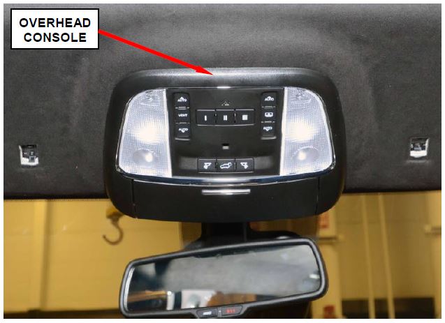
- Remove and save the front overhead console as an assembly (Figure 9).
- For vehicles equipped with rear overhead DVD console, remove and save the rear overhead DVD console.
Figure 9 – Front Overhead Console
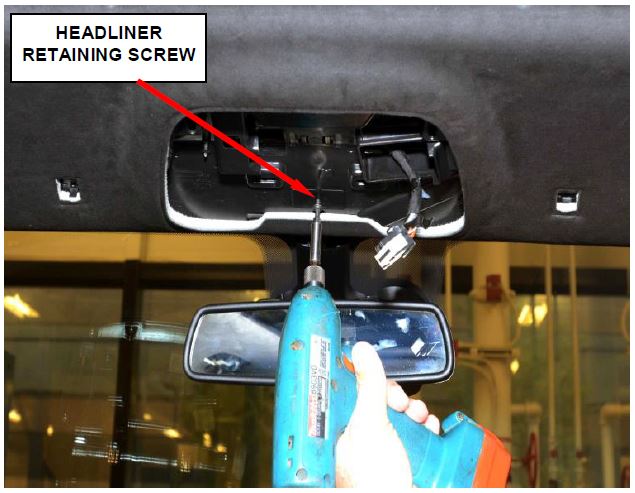
- Remove and save the headliner retaining screw (Figure 10).
- Remove and discard the three retaining screws holding the right and left side sun visors (Figure 8).
CAUTION: Do not allow the sun visors to hang by the wires.
Figure 10 – Headliner Retaining Screw
- Carefully lower the front of the headliner to gain access to the right and left side sun visor wiring.
CAUTION: Carefully lower the headliner just enough to gain access to the sun visor wiring. Do not lower the headliner any more than necessary to prevent kinking the headliner.
- Carefully disconnect the electrical connectors for the right and left sun visor.
- Remove and discard the original sun visors.
- Inspect the right and left side headliner wiring for broken or bare wires. Repair wires if required.
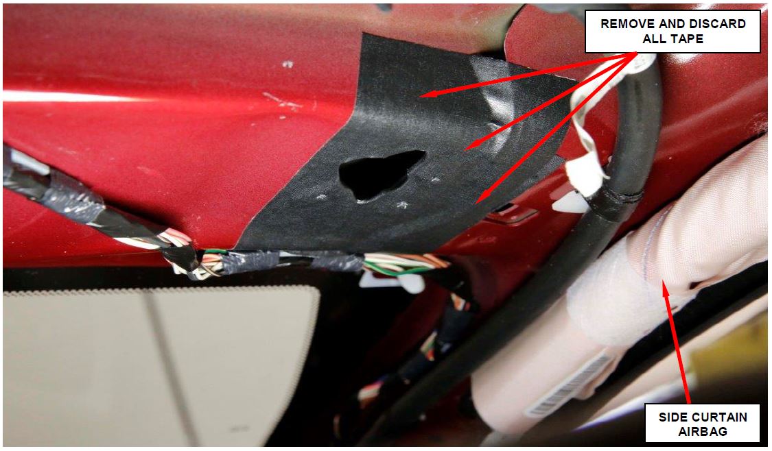
- For vehicles that had Safety Recall P36 performed, remove all protective and abrasion tape applied to the right and left visor hole openings (Figure 11).
Figure 11 – Remove and Discard the Abrasion Tape and Tape Patches from Left and Right Visor Hole Openings (right side shown)
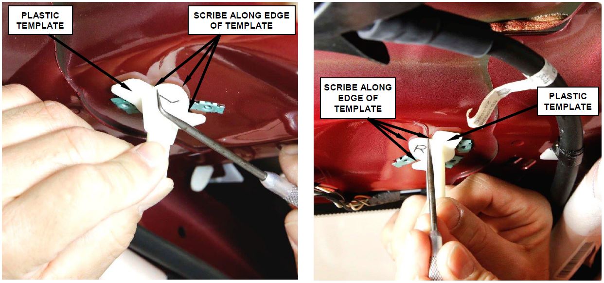
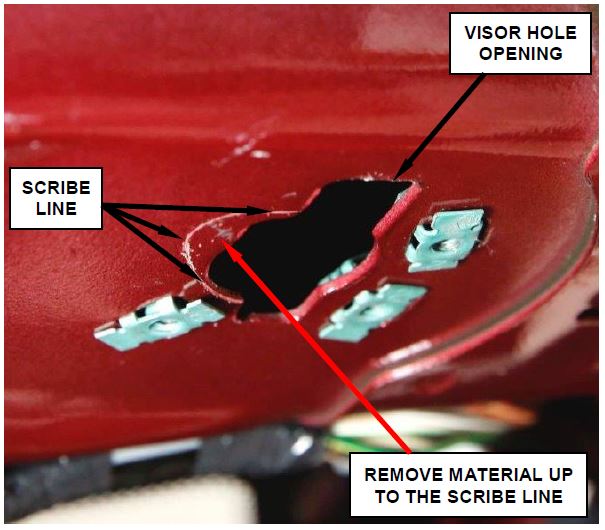
Figure 12 – Install Template and Scribe Cut Line
- Hold the plastic template marked “L” into the left visor hole opening in the roof panel and scribe a line on the sheet metal (Figure 12).
- Remove and save the left template. Verify that the scribe mark is visible (Figure 13).
- Hold the plastic template marked “R” into the right visor hole opening in the roof panel and scribe a line on the sheet metal (Figure 12).
- Remove and save the right template. Verify that the scribe mark is visible (Figure 13).
Figure 13 – Scribe Mark (right side shown)
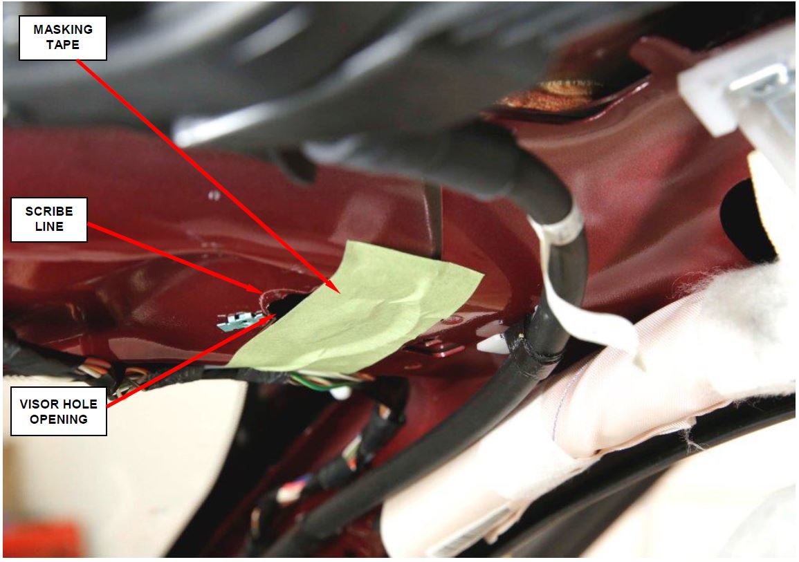
- Apply masking tape (or equivalent) over the right and left visor hole opening in the sheet metal panel as shown in Figure 14.
NOTE: Covering the visor hole opening with masking tape will greatly decrease the potential for metal shaving being thrown about the interior of the vehicle during the grinding process.
Figure 14 – Apply Masking Tape to Cover Majority of the Visor Hole Opening (right side shown)
- Place a fender cover or equivalent over the defroster vents on the instrument panel to prevent any metal shavings from entering the defroster vents.
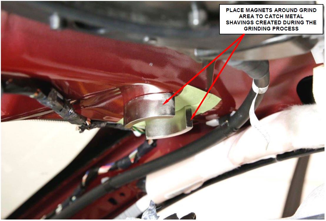
- Install the two supplied magnets around the left visor hole to catch any metal shavings created from the grinding process (Figure 15).
CAUTION: Failure to use magnets to catch the metal shavings will allow the shavings to fall throughout the interior of the vehicle and on the top of the headliner.
Figure 15 – Install Magnets to Catch Metal Shavings (right side shown)
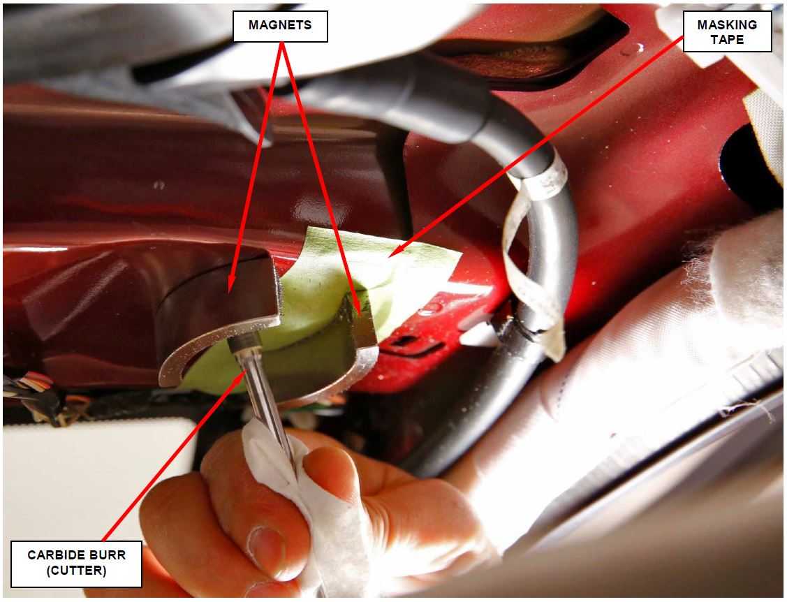
- Using the supplied carbide burr and a die grinder, grind a relief in the left visor hole opening (Figure 16).
WARNING: Wear safety glasses and protective gloves to prevent personal injury.
CAUTION: Do not grind beyond the scribe marks made in Steps 31 and 33.
- Carefully remove the magnets and tape from the left visor hole.
- Using 320 grit emery cloth, remove any burrs from the left visor hole, remove masking tape and clean away any dust/debris.
- Repeat Steps 37 through 40 for the right visor
Figure 16 – Grind Away Sheet Metal Inside Scribe Mark (right side shown)
- Apply primer with a brush to any bare metal at the right and left visor holes that was created by the grinding process.
CAUTION: Do not spray primer directly from the can onto the vehicle. Primer over-spray may damage interior surfaces. Spray product in a container and brush onto vehicle.
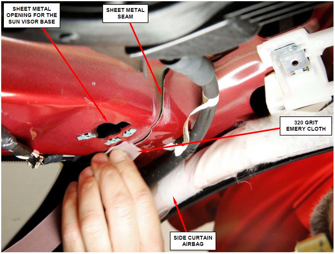
- Using 320 grit emery cloth, dull the edge of the sheet metal seam on the right and left upper “A” pillar (Figure 17).
Figure 17 – Dull Sheet Metal Seam Edge (right side shown)
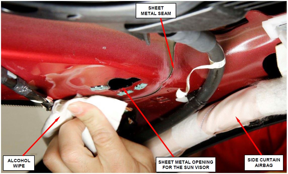
- Clean the sheet metal edge with an alcohol wipe to remove any dust and/or debris (Figure 18).
Figure 18 – Clean Seams with Alcohol Wipe (right side shown)
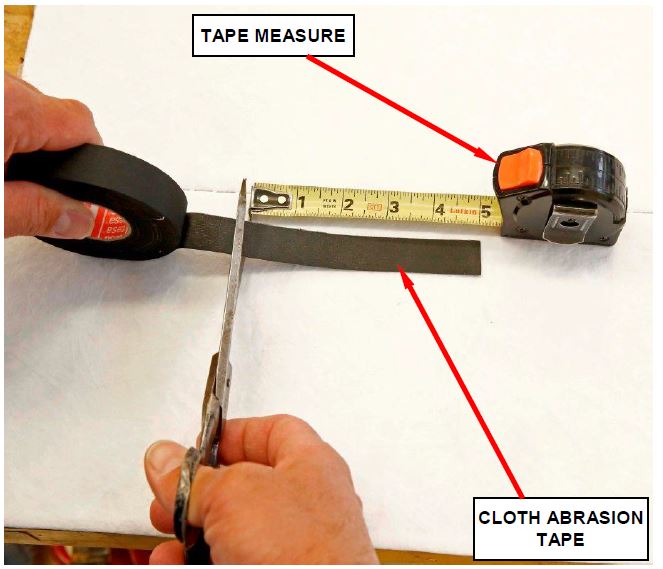
- Cut two pieces of cloth abrasion tape 5 inches (125 mm) long (Figure 19).
Figure 19 – Cut Two Piece of Cloth Abrasion Tape
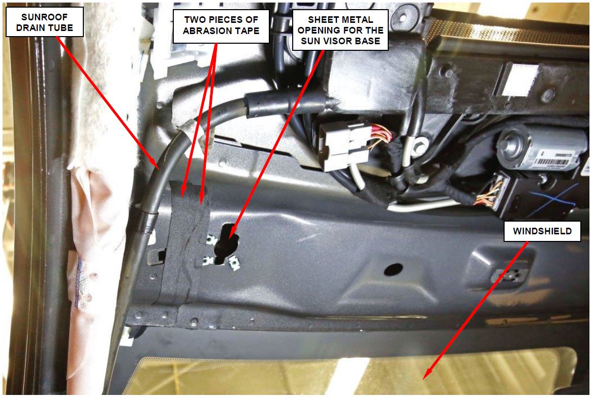
Figure 20 – Apply the Two 5 Inch Strips of Tape Over Sheet Metal Seam (left side shown)
- Apply the two pieces of cloth abrasion tape over the sheet metal seam located at the top of the “A” pillar (Figure 20).
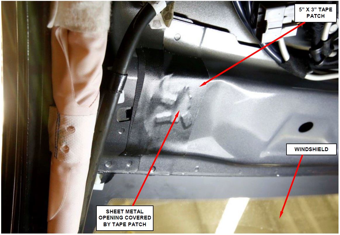
Figure 21 – Apply 5”x 3” Tape Patch over the Abrasion Tape (left side shown)
- Apply one piece of (5”x 3”) tape patch over the tape applied in Step 46 (Figure 21).
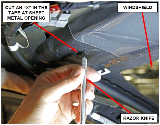
- Using a razor knife, cut an “X” in the tape where it spans the sheet metal opening for the sun visor base (Figure 22).
WARNING: Use extreme care when using a razor knife to prevent personal injury.
Figure 22 – Cut an “X” in the Tape (left side shown)
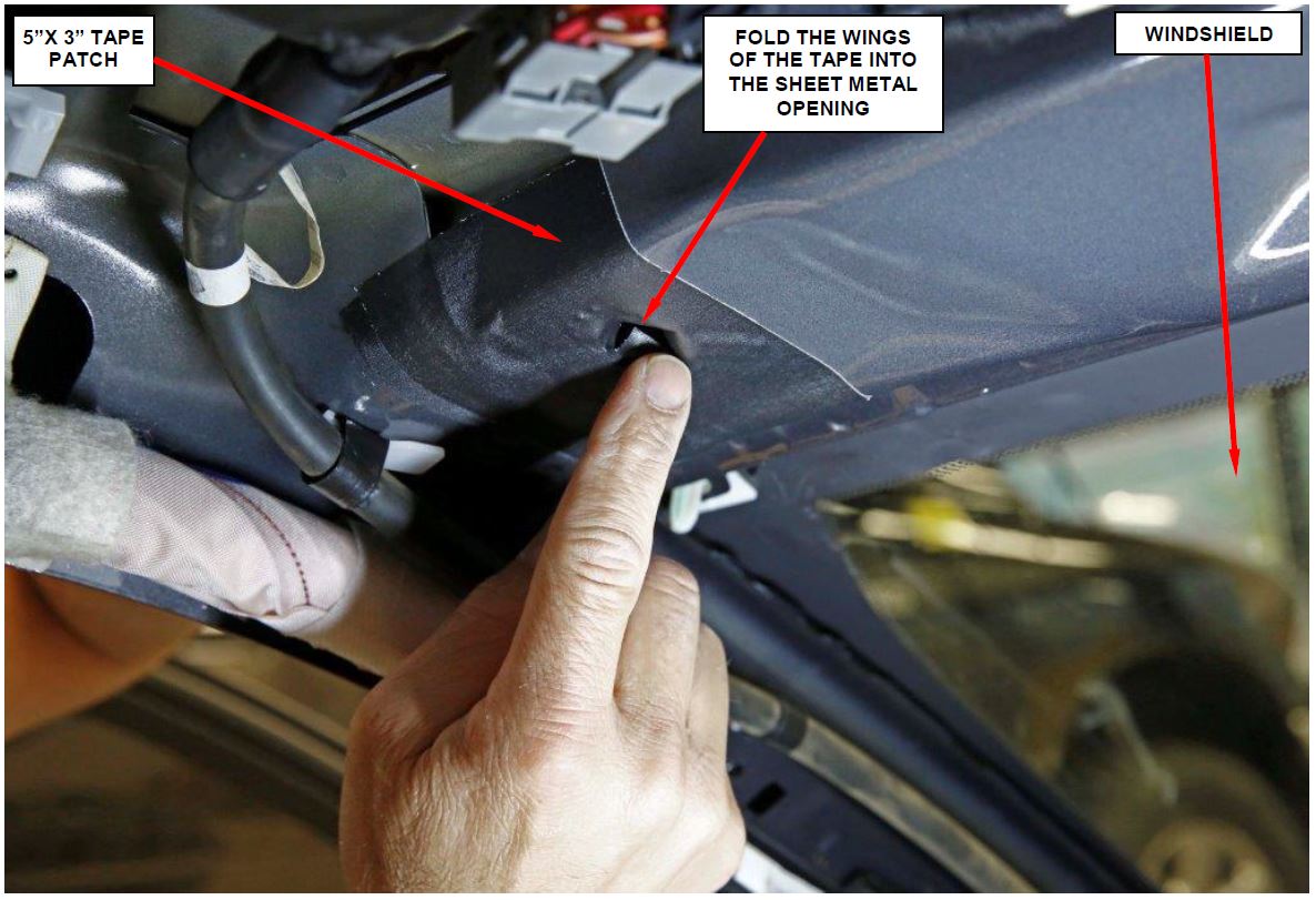
Figure 23 – Fold Tape Wings into the Hole (left side shown)
- Fold the wings of the tape into the sheet metal opening (Figure 23).
- Repeat Steps 44 through 48 on the other sheet metal opening.
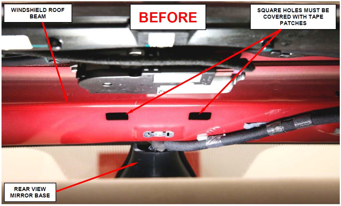
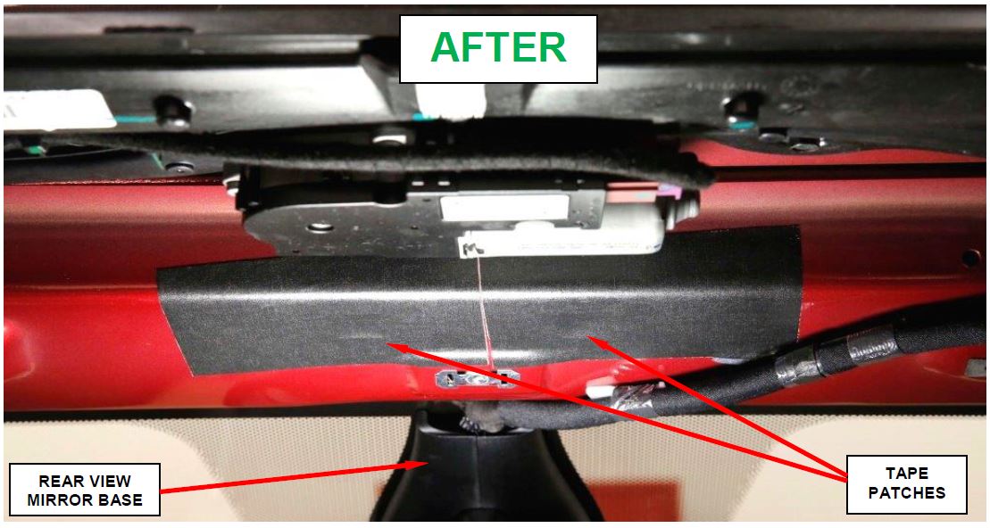
- Apply two tape patches over the square holes in the center of the windshield roof beam (Figure 24).
Figure 24 – Apply One Tape Patch Over Each Square Hole in the Windshield Roof Beam (vehicle with sunroof option shown)
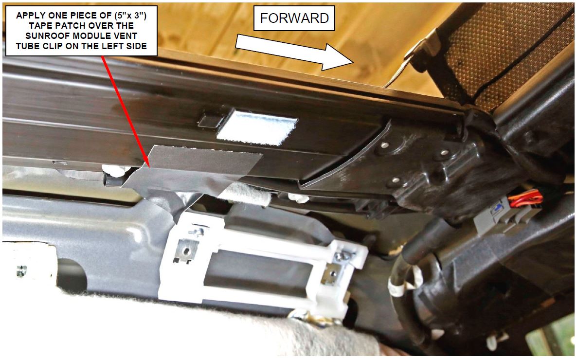
Figure 25 – Apply Tape Patch Over Sunroof Module Vent Tube Clip (Dual Pane Sunroof Left Side Only)
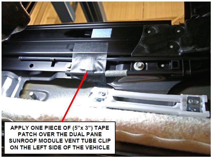
- For vehicles equipped with a Dual Pane Sunroof and did not have recall P36 performed, apply one piece of (5”x 3”) tape patch over the sunroof module vent tube clip on the left side of the vehicle (Figure 25 and 26).
Figure 26 – Apply Tape Patch Over Sunroof Module Vent Tube Clip (Dual Pane Sunroof Only)
- Remove and discard the original right and left side sun visor wire guides.
- Install the new right and left side sun visor wire guides onto the back side of the headliner.
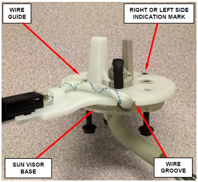
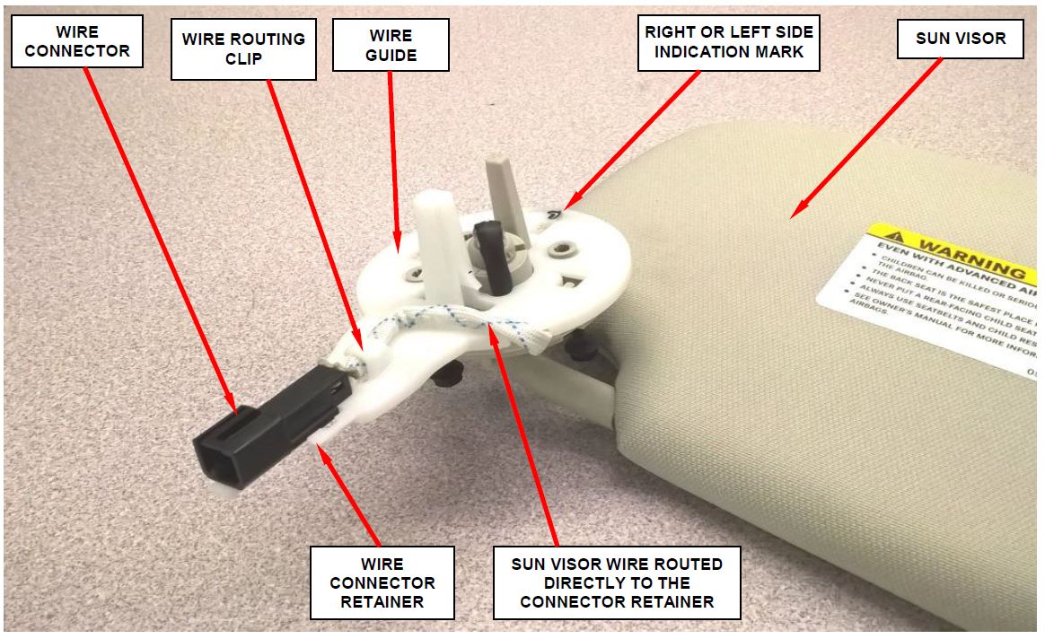
NOTE: The plastic wire guides are marked “R” for the right side and “L” for the left side (Figure 27 and 28).
Figure 27 – Sun Visor Wire Routing
(Parts removed from vehicle for photographic purposes only)
- Snap the new right and left side sun visors into place on the headliner.
- Route the sun visor wire as shown in Figure 28. Then connect the sun visor wire harness electrical connector to the wire guide connector retainer.
NOTE: Figures 28 show the sun visor parts assembled without the headliner in place.
CAUTION: Be sure to route the sun visor wire in the wire groove on the plastic wire guide (Figure 28).
CAUTION: It is critical that the sun visor wire remains under the wire routing clip shown in Figure 28 when reinstalling the visor to prevent improper wire routing.
Figure 28 – Sun Visor Wire Routing
(Parts removed from vehicle for photographic purposes only)
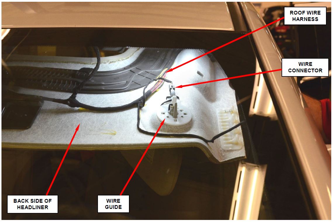
Figure 29 – Wire Guide Connector (viewed through windshield)
- Connect the roof wire harness connector to the sun visor electrical connector (Figure 29).
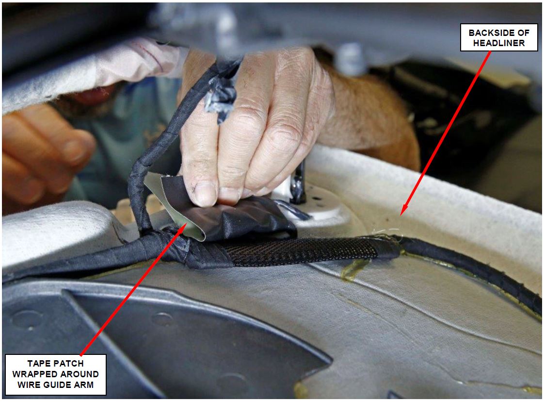
Figure 30 – Wrap Tape Patch Around the Right and Left Wire Guide Arms
- Apply a piece of (5” x 3”) tape patch around the right and left side wire guide arm as shown in Figure 30.
- Carefully lift the headliner into position and snap the wire guides into the roof structure.
- Install the right and left side sun visor anchors (Figure 8).
- For vehicles equipped with a dual pane sunroof, remove and save right and left headliner opening supports (Special Tool 2021400230).
- Install the three sun visor retaining screws for the right and left side sun visors (Figure 8).
CAUTION: Do not use power tools to install the three sun visor retaining screws. Use only hand tools when installing the three sun visor retaining screws. Pay close attention during sun visor retaining screw installation to prevent accidentally driving a screw through the sun visor wire harness.
- Install the right and left side sun visor screw covers.
- Install the headliner retaining screw (Figure 10).
- Install the front overhead console as an assembly (Figure 9).
- For vehicles equipped with rear overhead DVD console, install the rear overhead DVD console.
- Install the right and left side front overhead grab handles (Figure 4).
- Install the right and left side “A” pillar covers (Figure 3).
CAUTION: Be sure to connect the tether to the “A” pillar cover.
- Install the right and left side front door weather seals (Figure 1).
- Install the right and left side front door opening sill plates.
- Connect the negative battery cable to the battery (Figure 2).
- Move both front seats to the full forward position.
- Install the right and left side upper and lower “B” pillar trim panels (Figure 5).
- Install the right and left side rear overhead grab handles (Figure 6).
- Install the right and left side rear door weather seals (Figure 5).
- Install the right and left side rear door opening sill plates.
- Using a suitable interior cleaner, clean the “A” and “B” pillar panels as required.
- Connect the wiTECH scan tool and clear all Diagnostic Trouble Codes (DTC’s).
- Disconnect the wiTECH scan tool from the vehicle.
- Return the vehicle to the customer.
Completion Reporting and Reimbursement
Claims for vehicles that have been serviced must be submitted on the DealerCONNECT Claim Entry Screen located on the Service tab. Claims submitted will be used by FCA to record recall service completions and provide dealer payments.
Use the following labor operation number and time allowance:
| Labor Operation Number | Time Allowance | |
|---|---|---|
| Replace right and left sun visor, install wire guides, and grind reliefs | 08-R7-11-82 | 2.2 hours |
| Related Operation | ||
| Repair one wire | 08-R7-11-50 | 0.1 hours |
| Repair two to four wires | 08-R7-11-51 | 0.2 hours |
| Optional Equipment | ||
| Dual pane sunroof | 08-R7-11-60 | 0.2 hours |
| Rear Overhead DVD Console | 08-R7-11-61 | 0.2 hours |
Add the cost of the recall parts package plus applicable dealer allowance to your claim.
NOTE: See the Warranty Information Center (WIC) Claim Processing Tip and the Warranty Administration Manual, Recall Claim Processing Section, for complete recall claim processing instructions.
Dealer Notification
To view this notification on DealerCONNECT, select “Global Recall System” on the Service tab, then click on the description of this notification.
Owner Notification and Service Scheduling
All involved vehicle owners known to FCA are being notified of the service requirement by first class mail. They are requested to schedule appointments for this service with their dealers. A generic copy of the owner letter is attached.
Enclosed with each owner letter is an Owner Notification postcard to allow owners to update our records if applicable.
Vehicle Lists, Global Recall System, VIP and Dealer Follow Up
All involved vehicles have been entered into the DealerCONNECT Global Recall System (GRS) and Vehicle Information Plus (VIP) for dealer inquiry as needed.
GRS provides involved dealers with an updated VIN list of their incomplete vehicles. The owner’s name, address and phone number are listed if known. Completed vehicles are removed from GRS within several days of repair claim submission.
To use this system, click on the “Service” tab and then click on “Global Recall System.” Your dealer’s VIN list for each recall displayed can be sorted by: those vehicles that were unsold at recall launch, those with a phone number, city, zip code, or VIN sequence.
Dealers must perform this repair on all unsold vehicles before retail delivery. Dealers should also use the VIN list to follow up with all owners to schedule appointments for this repair.
Recall VIN lists may contain confidential, restricted owner name and address information that was obtained from the Department of Motor Vehicles of various states. Use of this information is permitted for this recall only and is strictly prohibited from all other use.
Additional Information
If you have any questions or need assistance in completing this action, please contact your Service and Parts District Manager.
Customer Services / Field Operations
FCA US LLC
SUN VISOR WIRING
IMPORTANT SAFETY RECALL
R71 / NHTSA 15V-879
This notice applies to your vehicle (VIN: xxxxxxxxxxxxxxxxx).
This notification letter is sent to you in accordance with the National Traffic and Motor Vehicle Safety Act.
Dear: (Name)
FCA has decided that a defect, which relates to motor vehicle safety, exists in certain 2011 and 2012 model year Jeep Grand Cherokee and Dodge Durango vehicles.
| The problem is… | The sun visors on your vehicle may experience a high resistance short at the sun visor vanity lamp wiring after a service repair to the sun visor, headliner or while gaining access above the headliner. This may result in an inoperative vanity lamp and/or an electrical fire. |
| What your dealer will do… | FCA will repair your vehicle free of charge. To do this, your dealer will replace the sun visors, modify the surrounding sheet metal and install vanity lamp wiring guides. The work will take about three hours to complete. However, additional time may be necessary depending on service schedules. |
| What you must do to ensure your safety… | Simply contact your Chrysler , Jeep, Dodge or RAM , Jeep, Dodge or RAM dealer right away to schedule a service appointment. Ask the dealer to hold the parts for your vehicle or to order them before your appointment. Please bring this letter with you to your dealer. dealer right away to schedule a service appointment. Ask the dealer to hold the parts for your vehicle or to order them before your appointment. Please bring this letter with you to your dealer. |
| If you need help… | If you have questions or concerns which your dealer is unable to resolve, please contact the FCA Recall Assistance Center at 1-800-853-1403. |
Please help us update our records by filling out the attached prepaid postcard if any of the conditions listed on the card apply to you or your vehicle. If you have further questions go to recalls.mopar.com.
If you have already experienced this specific condition and have paid to have it repaired, you may visit www.fcarecallreimbursement.com to submit your reimbursement request online or you can mail your original receipts and proof of payment to the following address for reimbursement consideration: FCA Customer Assistance, P.O. Box 21-8004, Auburn Hills, MI 48321-8007, Attention: Recall Reimbursement. Once we receive and verify the required documents, reimbursement will be sent to you within 60 days. If you’ve had previous repairs and/or reimbursement you may still need to have the recall repair performed on your vehicle.
If your dealer fails or is unable to remedy this defect without charge and within a reasonable time, you may submit a written complaint to the Administrator, National Highway Traffic Safety Administration, 1200 New Jersey Ave., S.E., Washington, DC 20590, or you can call the toll-free Vehicle Safety Hotline at 1-888-327-4236 (TTY 1-800-424-9153), or go to safercar.gov.
We’re sorry for any inconvenience, but we are sincerely concerned about your safety. Thank you for your attention to this important matter.
Customer Services / Field Operations
FCA US LLC
Note to lessors receiving this recall: Federal regulation requires that you forward this recall notice to the lessee within 10 days.
 Loading...
