| “This site contains affiliate links for which OEMDTC may be compensated” |
NHTSA Campaign Number: 16V047
Component(s): AIR BAGS
Potential Number of Units Affected: 111,519
Manufacturer: Chrysler (FCA US LLC)
SUMMARY:
FCA US LLC (Chrysler ) is recalling certain model year 2009 Dodge
 Journey vehicles manufactured December 31, 2007, to August 31, 2008, 2008-2009 Dodge
 Grand Caravan and Chrysler
 Town and Country vehicles manufactured June 18, 2007, to August 31, 2008.
In the affected vehicles, the air bag control units may corrode and fail.
CONSEQUENCE:
If the air bag control unit fails, the air bags may not deploy in the event of a crash, increasing the risk of occupant injury.
Additionally, the air bags may inadvertently deploy, increasing the risk of a crash.
REMEDY:
Chrysler will notify owners, and dealers will replace the air bag control unit, free of charge.
Interim notices were sent to owners on March 7, 2016.
Owners will receive a second notice when remedy parts become available in the fourth quarter of 2016.
Owners may contact Chrysler customer service at 1-800-853-1403.
Chrysler ’s number for this recall is S07.
NOTES:
Owners may also contact the National Highway Traffic Safety Administration Vehicle Safety Hotline at 1-888-327-4236 (TTY 1-800-424-9153), or go to www.safercar.gov.
Check if your Vehicle has a Recall
Dealer Service Instructions for:
Revised December 2016
Safety Recall S07 / NHTSA 16V-047
Occupant Restraint Control Module
NOTE: An additional labor operation number has been added to the recall and the “Parts Information” section has been revised.
SPECIAL NOTE: A small number of vehicles may be involved in both Safety Recall L01 and S07. If Safety Recall L01 has been completed, Safety Recall S07 is not required. Use the inspection labor operation in this recall to relieve the vehicle from Safety Recall S07. If Safety Recall L01 has not been completed, only perform Safety Recall S07. Safety Recall L01 has been cancelled.
Models
NOTE: This recall applies only to the above vehicles built at Windsor Assembly plant (“R” in the 11th VIN Position) through August 31, 2008 (MDH083119) or St. Louis South Assembly plant (“B” in the 11th VIN Position) through August 28, 2008 (MDH 082814).
| 2009 | (JC) | Dodge Journey Journey |
NOTE: This recall applies only to the above built through August 30, 2008 (MDH 083000).
| IMPORTANT: Some of the involved vehicles may be in dealer used vehicle inventory. Dealers should complete this recall service on these vehicles before retail delivery. Dealers should also perform this recall on vehicles in for service. Involved vehicles can be determined by using the VIP inquiry process. |
Subject
The Occupant Restraint Control (ORC) module on about 110,900 of the above vehicles may experience a malfunction due to corrosion of the power supply integrated circuit. This could result in an illuminated airbag warning lamp with the possibility of no airbag deployment in a crash necessitating airbag deployment or an inadvertent airbag deployment without an illuminated airbag warning lamp. Either of these conditions could increase the risk of a crash and/or injury to front seat vehicle occupants.
Repair
The original ORC module must be replaced on all involved vehicles.
NOTE: Some vehicles involved in this recall were also involved in Safety Recall K25. If not previously performed, Safety Recall K25 must also be performed at this time.
WARNING: Failure to perform Safety Recall K25, if required, could allow water from the HVAC unit to contaminate the new ORC module. Do not complete Recall S07 without verifying on the VIP system that Safety Recall K25 has been performed.
Parts Information
| Part Number | Description |
|---|---|
| CBL7S071AA | ORC Module (JC models with SABC & Thorax) |
| CBL7S072AA | ORC Module (JC models without SABC & Thorax) |
| CBL7S073AA | ORC Module (JC models with SABC & Thorax 5-passenger calibration) |
| CBL7S074AA | ORC Module (Non-NAFTA (YAB sales code) JC models with 3rd row 50/50 Fold/ Reclining Seat, SABC & Thorax) |
| CBL7S075AA | ORC Module (Non-NAFTA (YAB sales code) JC models with 5-passenger calibration, SABC & Thorax) |
| CBL7S07AAA | ORC Module (RT models built on or before 02/25/2008 with SABC) |
| CAN3L011AB | ORC Module (RT models built on or after 02/26/2008 with SABC) |
| CBL7S07BAA | ORC Module (RT models built on or before 02/25/2008 without SABC) |
| CBL7S077AA | ORC Module (RT models built on or after 02/26/2008 without SABC) |
| CBL7S078AA | ORC Module (Non-NAFTA (YAB sales code) RT models built on or after 02/26/2008 with SABC and Thorax) |
Definitions:
SABC = Side AirBag Curtain.
Thorax = Airbag located in the front seat seatback side cushion.
5-passenger calibration = Vehicles without sales code CAU.
7-passenger calibration = Vehicles with sales code CAU.
Each dealer to whom vehicles in the recall were assigned will receive enough ORC modules to service about 20% of those vehicles.
Parts Return
No parts return required for this campaign.
Special Tools
The following special tools are required to perform this repair:
| wiTECH micro pod II |
| Laptop Computer |
| wiTECH Software |
Service Procedure
A. Replace ORC Module (RT Models)
WARNING: To avoid serious or fatal injury on vehicles equipped with side curtain airbags, disable the Supplemental Restraint System (SRS) before attempting any Occupant Restraint Controller (ORC) module diagnosis or service. The ORC module contains a rollover sensor, which enables the system to deploy the side SRS components in the event of a vehicle rollover event. If an ORC module is accidentally rolled during service while still connected to battery power, the side SRS components will deploy. Disconnect and isolate the battery negative (ground) cable, then wait two minutes for the system capacitor to discharge before performing further diagnosis or service. This is the only sure way to disable the SRS. Failure to take the proper precautions could result in accidental airbag deployment.
WARNING: To avoid serious or fatal injury on vehicles equipped with airbags, disable the Supplemental Restraint System (SRS) before attempting any ORC module diagnosis or service. Disconnect and isolate the battery negative (ground) cable, then wait two minutes for the system capacitor to discharge before performing further diagnosis or service. This is the only sure way to disable the SRS. Failure to take the proper precautions could result in accidental airbag deployment.
WARNING: To avoid serious or fatal injury, never strike or drop the Occupant Restraint Controller (ORC) module, as it can damage the impact sensor or affect its calibration. The ORC module contains the impact sensor, which enables the system to deploy the Supplemental Restraint System (SRS) components. If an ORC module is accidentally dropped during service, the module must be scrapped and replaced with a new unit. Failure to observe this warning could result in accidental, incomplete, or improper SRS component deployment.
- Disconnect and isolate the battery negative cable. Wait two minutes for the system capacitor to discharge.
CAUTION: Vehicles equipped with a MyGig radio (sales code REN or REZ) must have the 30 amp fuse for the radio removed prior to disconnecting or reconnecting the battery (for fuse location please consult the vehicle’s fuse cover). Disconnecting and reconnecting the battery can cause electrical spikes that may damage the MyGig radio. Removal of the radio 30 amp fuse will prevent this from occurring.
- If equipped, unlatch and remove the center console located between the two front seats.
- Remove and save the six lower storage bin retaining push pins.
- Remove and save the storage bin shroud.
- Remove and save the cup holder.
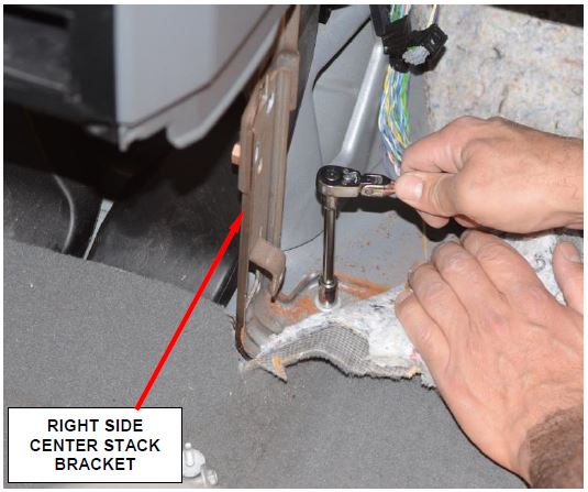
- Remove and save the right side center stack bracket (Figure 1).
Figure 1 – Right Side Center Stack Bracket
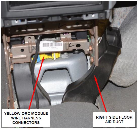
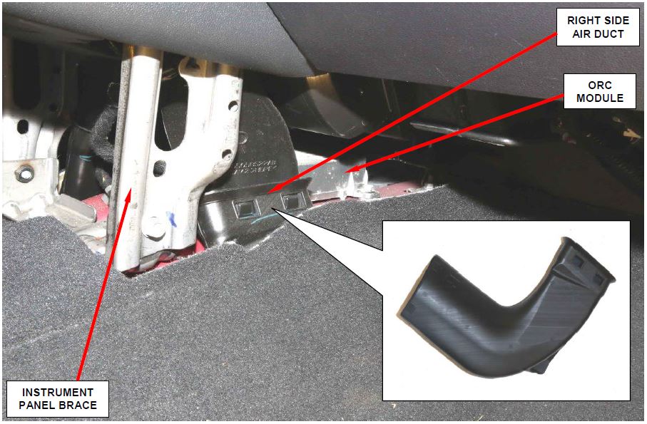
- If equipped, carefully relocate the right side floor air duct (Figure 2).
- Vehicles equipped with Electronic Stability Program (ESP), remove and save the ESP dynamics sensor from the right side of the ORC module mounting bracket.
- Disconnect the yellow instrument panel wire harness connector and body wire harness connector from the ORC module yellow electrical receptacles located on the rearward facing side of the ORC module (Figure 2).
NOTE: To disconnect the wire harness connectors from the ORC module, depress the release tab and lift the lever arm to the fully open position on each connector.
Disconnecting the 36 pin connector first will allow for easier access when disconnecting the 72 pin connector.
Figure 2 – Right Side Floor Air Duct
- Remove and save the three screws that secure the ORC module to the ORC mounting bracket.
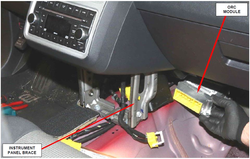
- Working from the right side of the transmission tunnel, lift the original ORC module far enough to disengage the locating pins and remove the original ORC module from the bracket. Discard the original ORC module.
- Working from the right side of the transmission tunnel, carefully position the new ORC module to the ORC module mounting bracket.
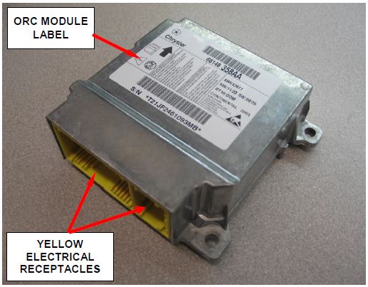
Figure 3 – ORC Module
NOTE: When the ORC module is correctly positioned, the arrow on the ORC module label will be pointed forward in the vehicle and the locating pins on the bottom of the ORC module will be engaged into the locating holes in the bracket.
- Install and tighten the three screws that secure the ORC module to the ORC module mounting bracket. Tighten the screws to 88 in. lbs. (10 N·m).
- Reconnect the body wire harness connector and the instrument panel wire harness connector to the ORC module yellow electrical receptacles located on the rearward facing side of the module (Figure 3). Be certain that the latches on both connectors are each fully engaged.
CAUTION: The lever arms of the wire harness connectors for the ORC module MUST be in the unlatched position before they are inserted into their connector receptacles on the ORC module or they may become damaged.
- Vehicles equipped with Electronic Stability Program (ESP), install the ESP dynamics sensor onto the right side of the ORC module mounting bracket.
- If equipped, place the right side floor air duct back into position (Figure 2).
- Install the right side center stack bracket (Figure 1).
- Install the cup holder.
- Install the center stack lower storage bin and six retaining push pins.
- If equipped, install the center console.
- Do not reconnect the battery negative cable at this time. The Supplemental Restraint System (SRS) verification test procedure must be performed following ORC module replacement.
- Perform the following Supplemental Restraints System Verification Test procedure:
a. Be certain that the diagnostic scan tool contains the latest version of the proper diagnostic software. Connect the scan tool to the 16-way Data Link Connector (DLC).
b. Turn the ignition switch to the “ON” position.
c. Check to be certain that nobody is in the vehicle, then reconnect the battery negative cable.
d. Using the scan tool, read and record the active (current) Diagnostic Trouble Code (DTC) data.
e. Next, use the scan tool to read and record any stored (historical) DTC data.
- New ORC modules are shipped in a “Locked Out” state and will set a B-2722 DTC “ORC LOCKED-ALL DEPLOYMENT DISABLED.” Perform the following ORC Module Initialization procedure using the wiTECH scan tool:
a. Select the ORC icon from the vehicle view screen.
b. Select the “Miscellaneous Functions” tab.
c. Select “Initialize ORC” from the list.
d. Follow the screen prompts on the wiTECH screen.
NOTE: This will erase the fault codes and initialize the ORC module.
- Turn the ignition switch to the “OFF” position for 15 seconds, and then back to the “ON” position. Observe the airbag indicator in the instrument cluster. The airbag indicator lamp should illuminate for four to six seconds, and then go out. This indicates that the SRS is functioning normally and that the repairs are complete.
- For vehicles equipped with a MyGig radio, install the 30 amp radio fuse.
- For vehicles involved in Safety Recall K25, perform Safety Recall K25 if not previously performed.
NOTE: Refer to Safety Recall K25 Dealer Service Instructions for the service procedure, labor operation numbers, and labor time allowances.
WARNING: Failure to perform Safety Recall K25, if required, could allow water from the HVAC unit to contaminate the new ORC module. Do not complete this recall without verifying on the VIP system that Safety Recall K25 has also been performed.
- Return the vehicle to the customer.
B. Replace ORC Module (JC Models)
WARNING: To avoid serious or fatal injury on vehicles equipped with side curtain airbags, disable the Supplemental Restraint System (SRS) before attempting any Occupant Restraint Controller (ORC) module diagnosis or service. The ORC module contains a rollover sensor, which enables the system to deploy the side SRS components in the event of a vehicle rollover event. If an ORC module is accidentally rolled during service while still connected to battery power, the side SRS components will deploy. Disconnect and isolate the battery negative (ground) cable, then wait two minutes for the system capacitor to discharge before performing further diagnosis or service. This is the only sure way to disable the SRS. Failure to take the proper precautions could result in accidental airbag deployment.
WARNING: To avoid serious or fatal injury on vehicles equipped with airbags, disable the Supplemental Restraint System (SRS) before attempting any ORC module diagnosis or service. Disconnect and isolate the battery negative (ground) cable, then wait two minutes for the system capacitor to discharge before performing further diagnosis or service. This is the only sure way to disable the SRS. Failure to take the proper precautions could result in accidental airbag deployment.
WARNING: To avoid serious or fatal injury, never strike or drop the Occupant Restraint Controller (ORC) module, as it can damage the impact sensor or affect its calibration. The ORC module contains the impact sensor, which enables the system to deploy the Supplemental Restraint System (SRS) components. If an ORC module is accidentally dropped during service, the module must be scrapped and replaced with a new unit. Failure to observe this warning could result in accidental, incomplete, or improper SRS component deployment.
- Disconnect and isolate the battery negative cable. Wait two minutes for the system capacitor to discharge.
- Using the following procedure, remove the center console from the top of the transmission tunnel:
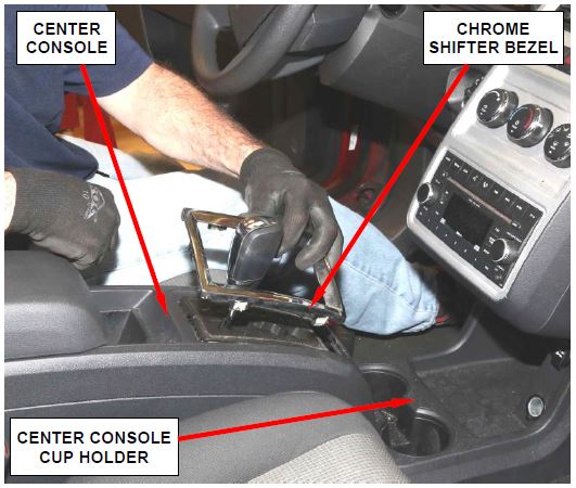
a. Using a plastic trim stick, carefully remove and save the chrome shifter bezel (Figure 4).
CAUTION: Use extreme care not to nick or scratch the chrome trim bezel.
Figure 4 – Chrome Shifter Bezel
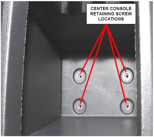
b. Remove and save the four retaining screws located in the center console storage bin (Figure 5).
c. Remove and save the plastic push pins at the front lower edge of the console.
d. Remove and save the center console.
Figure 5 – Console Retaining Screws Located in Center Console Storage Bin
- Using the following procedure, remove and save the center console cup holder.
a. Remove and save the center console cup holder liner.
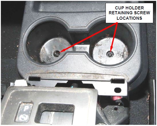
b. Remove and save the two retaining screws located on the bottom of the cup holder pockets (Figure 6).
Figure 6 – Center Console Cup Holder Retaining
c. Remove and save the four gear shift retaining nuts.
d. Relocate the gear shift assembly slightly rearward without disconnecting the gear shift linkage or wiring.
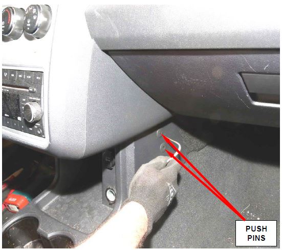
e. Disengage the four push pins on the side of the cup holder panel (two on each side) (Figure 7).
f. Partially remove the cup holder assembly and disconnect wiring.
g. Carefully remove the cup holder assembly.
- Remove and save the left side panel.
Figure 7 – Cup Holder Push Pins (right side shown)
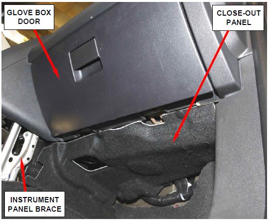
- Remove and save the right close-out panel (Figure 8).
Figure 8 – Right Side Close-Out Panel
- Remove and save the right side air duct (Figure 9).
- Disconnect the instrument panel wire harness connector, followed by the body wire harness connector from the yellow Occupant Restraint Controller (ORC) connector receptacles located on the rearward facing side of the module.
NOTE: To disconnect the wire harness connectors from the ORC, depress the release tab and lift the lever arm to the fully open position on each connector.
Figure 9 – Right Side Air Duct
- Remove and save the three bolts that secure the ORC to the ORC floor bracket.
- Lift the ORC far enough to disengage the locating pins and remove the ORC from the bracket (Figure 10).
Figure 10 – ORC Module
- Carefully position the new Occupant Restraint Controller (ORC) to the original ORC bracket.
NOTE: When the ORC is correctly positioned, the arrow on the ORC label will be pointed forward in the vehicle and the locating pins on the bottom of the ORC will be engaged into the locating holes in the ORC floor bracket.
- Install and tighten the three bolts that secure the ORC to the ORC floor bracket. Tighten the bolts to 108 in. lbs. (12.5 N·m).
- First reconnect the body wire harness connector, followed by the instrument panel wire harness connector to the ORC connector receptacles located on the rearward facing side of the module. Be certain that the latches on both connectors are each fully engaged.
CAUTION: The lever arms of the wire harness connectors for the ORC MUST be in the unlatched position before they are inserted into their connector receptacles on the ORC or they may become damaged.
- Install floor air duct.
- Install right side close out panel.
- Install left side panel.
- Install the cup holder assembly onto the top of the floor panel transmission tunnel.
- Place gear shift assembly into position and install retaining nuts. Tighten the nuts to 71 in. lbs. (8 N·m).
- Do not reconnect the battery negative cable at this time. Continue with Section C. SRS Verification Test.
C. SRS Verification Test
- During the following test, the battery negative cable remains disconnected and isolated, as it was during the Supplemental Restraint System (SRS) component removal and installation procedures.
- Be certain that the diagnostic scan tool contains the latest version of the proper diagnostic software. Connect the scan tool to the 16-way Data Link Connector (DLC). The DLC is located on the driver side lower edge of the instrument panel within a rectangular cutout in the lower instrument panel reinforcement, just forward of the instrument panel steering column opening cover.
- Turn the ignition switch to the ON position and exit the vehicle with the scan tool.
- Check to be certain that nobody is in the vehicle, then reconnect the battery negative cable.
- Using the scan tool, read and record the active (current) Diagnostic Trouble Code (DTC) data.
- Next, use the scan tool to read and record any stored (historical) DTC data.
- If any DTC is found in Step 5 or Step 6, refer to the appropriate diagnostic information.
- Use the scan tool to erase the stored DTC data. If any problems remain, the stored DTC data will not erase. Refer to the appropriate diagnostic information to diagnose any stored DTC that will not erase. If the stored DTC information is successfully erased, go to Step 9.
- Turn the ignition switch to the OFF position for about 15 seconds, and then back to the ON position. Observe the airbag indicator in the instrument cluster. It should light from four to six seconds, and then go out. This indicates that the SRS is functioning normally and that the repairs are complete. If the airbag indicator fails to light, or lights and stays ON, there is still an active SRS fault or malfunction. Refer to the appropriate diagnostic information to diagnose the problem.
- Continue with Section D. ORC Module Initialization.
D. ORC Module Initialization
CAUTION: New ORC modules are shipped in a “Locked Out” state and will set a B-2722 fault code “ORC LOCKED-ALL DEPLOYMENT DISABLED.” Perform the following ORC Module Initialization procedure using the wiTECH scan tool.
- Select the ORC icon from the vehicle view screen.
- Select the “Miscellaneous Functions” tab.
- Select “Initialize ORC” from the list.
- Follow the screen prompts on the wiTECH screen.
NOTE: This will erase the fault codes and initialize the ORC module.
- Return the vehicle to the customer.
Completion Reporting and Reimbursement
Claims for vehicles that have been serviced must be submitted on the DealerCONNECT Claim Entry Screen located on the Service tab. Claims submitted will be used by FCA to record recall service completions and provide dealer payments.
Use one of the following labor operation numbers and time allowances:
| Labor Operation Number | Time Allowance | |
|---|---|---|
| Safety Recall L01 was previously performed (2008 RT models only) | 08-S0-71-81 | 0.0 hours |
| Replace ORC module (RT Models) | 08-S0-71-82 | 0.8 hours |
| Replace ORC module (JC Models) | 08-S0-71-83 | 0.9 hours |
| Special Service Operation | 95-23-30-92 | $5.00 |
| Flat Fee for Inspecting for L01 completion | 95-23-30-92 | $5.00 |
Add the cost of the recall parts package plus applicable dealer allowance to your claim.
NOTE: See the Warranty Administration Manual, Recall Claim Processing Section, for complete recall claim processing instructions.
Dealer Notification
To view this notification on DealerCONNECT, select “Global Recall System” on the Service tab, then click on the description of this notification.
Owner Notification and Service Scheduling
All involved vehicle owners known to FCA are being notified of the service requirement by first class mail. They are requested to schedule appointments for this service with their dealers. A generic copy of the owner letter is attached.
Enclosed with each owner letter is an Owner Notification postcard to allow owners to update our records if applicable.
Vehicle Lists, Global Recall System, VIP and Dealer Follow Up
All involved vehicles have been entered into the DealerCONNECT Global Recall System (GRS) and Vehicle Information Plus (VIP) for dealer inquiry as needed.
GRS provides involved dealers with an updated VIN list of their incomplete vehicles. The owner’s name, address and phone number are listed if known. Completed vehicles are removed from GRS within several days of repair claim submission.
To use this system, click on the “Service” tab and then click on “Global Recall System.” Your dealer’s VIN list for each recall displayed can be sorted by: those vehicles that were unsold at recall launch, those with a phone number, city, zip code, or VIN sequence.
Dealers must perform this repair on all unsold vehicles before retail delivery. Dealers should also use the VIN list to follow up with all owners to schedule appointments for this repair.
Recall VIN lists may contain confidential, restricted owner name and address information that was obtained from the Department of Motor Vehicles of various states. Use of this information is permitted for this recall only and is strictly prohibited from all other use.
Additional Information
If you have any questions or need assistance in completing this action, please contact your Service and Parts District Manager.
Customer Services / Field Operations
FCA US LLC
OCCUPANT RESTRAINT CONTROL MODULE
IMPORTANT SAFETY RECALL
S07 / NHTSA 16V-047
This notice applies to your vehicle (VIN: xxxxxxxxxxxxxxxxx).
This notice is sent to you in accordance with the National Traffic and Motor Vehicle Safety Act.
Dear: (Name)
FCA has decided that a defect, which relates to motor vehicle safety, exists in certain 2008 and 2009 model year Dodge Journey, Dodge
 Grand Caravan, Chrysler
 Grand Voyager, and Chrysler
 Town & Country vehicles.
| The problem is… | The Occupant Restraint Control (ORC) module on your vehicle may experience a malfunction due to corrosion of the power supply integrated circuit. This could result in an illuminated airbag warning lamp with the possibility of no airbag deployment in a crash necessitating airbag deployment or an inadvertent airbag deployment without an illuminated airbag warning lamp. Either of these conditions could increase the risk of a crash and/or injury to front seat vehicle occupants. |
| What your dealer will do… | FCA will repair your vehicle free of charge. To do this, your dealer will replace the ORC module. The work will take about two hours to complete. However, additional time may be necessary depending on service schedules. |
| What you must do to ensure your safety… | Simply contact your Chrysler , Jeep , Jeep , Dodge , Dodge or RAM or RAM dealer right away to schedule a service appointment. Ask the dealer to hold the parts for your vehicle or to order them before your appointment. Please bring this letter with you to your dealer. dealer right away to schedule a service appointment. Ask the dealer to hold the parts for your vehicle or to order them before your appointment. Please bring this letter with you to your dealer. |
| If you need help… | If you have questions or concerns which your dealer is unable to resolve, please contact the |
FCA Group Recall Assistance Center at either fcarecalls.com or 1-800-853-1403.
Please help us update our records by filling out the attached prepaid postcard if any of the conditions listed on the card apply to you or your vehicle. If you have further questions go to fcarecalls.com.
If you have already experienced this specific condition and have paid to have it repaired, you may visit www.fcarecallreimbursement.com to submit your reimbursement request online or you can mail your original receipts and proof of payment to the following address for reimbursement consideration: FCA Customer Assistance, P.O. Box 21-8004, Auburn Hills, MI 48321-8007, Attention: Recall Reimbursement. Once we receive and verify the required documents, reimbursement will be sent to you within 60 days. If you’ve had previous repairs and/or reimbursement you may still need to have the recall repair performed on your vehicle.
If your dealer fails or is unable to remedy this defect without charge and within a reasonable time, you may submit a written complaint to the Administrator, National Highway Traffic Safety Administration, 1200 New Jersey Ave., S.E., Washington, DC 20590, or you can call the toll-free Vehicle Safety Hotline at 1-888-327-4236 (TTY 1-800-424-9153), or go to safercar.gov.
We’re sorry for any inconvenience, but we are sincerely concerned about your safety. Thank you for your attention to this important matter.
Customer Services / Field Operations
FCA US LLC
Note to lessors receiving this recall: Federal regulation requires that you forward this recall notice to the lessee within 10 days.
 Loading...
 Loading...
