| “This site contains affiliate links for which OEMDTC may be compensated” |
Dealer Service Instructions for:
Revised October 2017
Customer Satisfaction Notification R28/R29 Engine Oil Contamination and Consumption
NOTE: Revised Parts Return instructions in Section A.
Models
| 2013-2014 | (ZD) | Dodge Viper Viper |
| IMPORTANT: Some of the involved vehicles may be in dealer vehicle inventory. Dealers should complete this repair on these vehicles before retail delivery. Dealers should also perform this repair on vehicles in for service. Involved vehicles can be determined by using the VIP inquiry process. |
Subject
The engine cylinder block on about 1,100 of the above vehicles may have been contaminated with abrasive debris.
Under rare conditions during high-speed right-hand cornering when the engine is at light throttle and high RPM, engine oil can be forced into the Make Up Air hose, resulting in unintended oil consumption.
Both of these conditions may compromise engine durability.
Repair
To address the R28 portion of this CSN, the oil contamination issue, the engine oil, oil filter and air filter must be changed then the oil filter must be sent to FCA for analysis.
If FCA’s analysis of the oil filter is positive for debris, the dealer will contact the customer to schedule replacement of the engine and related oil cooler components. If a new engine is not required, the dealer will contact the customer to inform them that they do not need to return to the dealership.
To address R29 portion of this CSN, the oil consumption issue, an updated oil management system must be installed which includes a new valve cover assembly with a relocated make up air (MUA) fitting and new baffle.
Alternate Transportation
Dealers should attempt to minimize customer inconvenience by placing the owner in a loaner vehicle if inspection determines that a long block engine replacement is required and the vehicle must be held overnight. . If you have questions or concerns which your dealer is unable to resolve, please contact the SRT Information Center at either fcarecalls.com or 1 855 778 8326.
Parts Information
| Description | Part Number |
|---|---|
| Kit, Engine Oil Consumption | CEAFR291AA |
| Each kit contains the following components: | |
| Description | Quantity |
| Cover, Cylinder Head Left Side | 1 |
| Cover, Ignition Coil Left Side | 1 |
| Foam Block | 1 |
| Hose, MUA | 1 |
| Description | Part Number |
|---|---|
| Filter, Oil | 05038041AA |
| Oil, Engine – 11 Quarts, 0W40 (MS 12633) | 68171066PA |
| Package, Oil Filter Inspection | 68307497AA |
| Filter, Air | 05038070AA |
NOTE: The following parts are required only if an engine long block replacement is required.
| Description | Part Number |
|---|---|
| Kit, Engine Long Block | CEAFR282AB |
| Each kit contains the following components: | |
| Description | Quantity |
| Engine Long Block | 1 |
| Cooler, Engine Oil | 1 |
| Line, Oil Cooler Outlet | 1 |
| Line, Oil Cooler Inlet | 1 |
| Instruction Sheet | 1 |
| Description | Part Number |
|---|---|
| V-Band Clamp, Exhaust (2 per vehicle) | 05290111AB |
| Gasket, Exhaust Manifold (2 per vehicle) | 05037703AA |
| Bolt, U-joint (4 per vehicle) | 06502581 |
| Strap, U-joint (2 per vehicle) | 4428723 |
| Bolt, Clutch Pressure Plate (6 per vehicle) | 06508880AA |
| Coolant, US OAT, Concentrate, 1 Gallon (MS-12106) | 68163848AB |
| Coolant, Canada OAT, Concentrate, 1 Gallon (MS-12106) | 68175338AB |
| Coolant, Mexico OAT, Concentrate, 1 Gallon (MS-12106) | 68175336AB |
IMPORTANT: Due to the small number of involved vehicles, no parts will be distributed to involved dealers initially. Parts may be ordered as needed to support scheduled repairs.
Parts Return
See Section A. Inspect Oil Filter for Contamination for parts return details.
Follow the Global Core Return procedure located on DealerCONNECT if an Engine Long Block is replaced (Kit # CEAFR282AB).
Special Tools
The following special tools are required to perform this repair:
- NPN wiTECH VCI Pod Kit
- NPN Laptop Computer
- NPN wiTECH Software
- 10034-2 Bracket, Rear Engine Lifting
- 10034-1 Bracket, Front Engine Lifting
- 10018 Clutch Alignment Tool
A. Change Oil and Inspect Oil Filter for Contamination
- Run the engine until achieving normal operating temperature.
- Position the vehicle on a level surface and turn the engine off.
- Open the hood.
- Record the last 8 characters of the VIN on the supplied instruction sheet and the supplied decal.
- Record the vehicle mileage on the supplied instruction sheet and the supplied decal.
- Raise the vehicle on hoist.
- Place a suitable drain pan under the oil filter.
- Wipe the oil filter clean and write the last 8 characters of the VIN on the oil filter using a permanent magic marker.
- Remove the oil filter and drain the oil from the filter.
- Place the oil filter into the supplied sealable bag and apply the decal to the bag. Return only one filter per kit.
- Install a NEW oil filter then tighten to 13 ft. lbs. (18 N·m).
NOTE: Apply a thin coat of engine oil to the oil filter seal before installation.
- Remove the drain plug from the oil pan and allow the oil to drain into pan. Inspect the drain plug threads for stretching or other damage. Replace the drain plug and the gasket if damaged.
- Install the drain plug in the oil pan and tighten to 25 ft. lbs. (34 N·m).
- Lower the vehicle and fill the crankcase with engine oil using 0W-40 (MS 12633).
- Start the engine and inspect for leaks.
- Stop the engine and inspect the oil level. Adjust the oil level as necessary.
- Place bagged oil filter and completed instruction sheet into box. Reseal the box and ship to:
Viper Warranty Engine Center (VWEC)
3500 Joslyn Rd
Auburn Hills, MI 48326
Attn: Dale Matthews
NOTE: Oil filter analysis results should take about one week. Viper Warranty Engine Center (VWEC) will email the results to the dealer. Be sure to provide an email address for inspection results on the supplied instruction sheet prior to shipping.
- Remove and discard the air filter and install a NEW air filter.
- Continue with Section B. Install Engine Oil Consumption Kit.
B. Install Engine Oil Consumption Kit
- Open the trunk lid. Disconnect the battery negative cable.
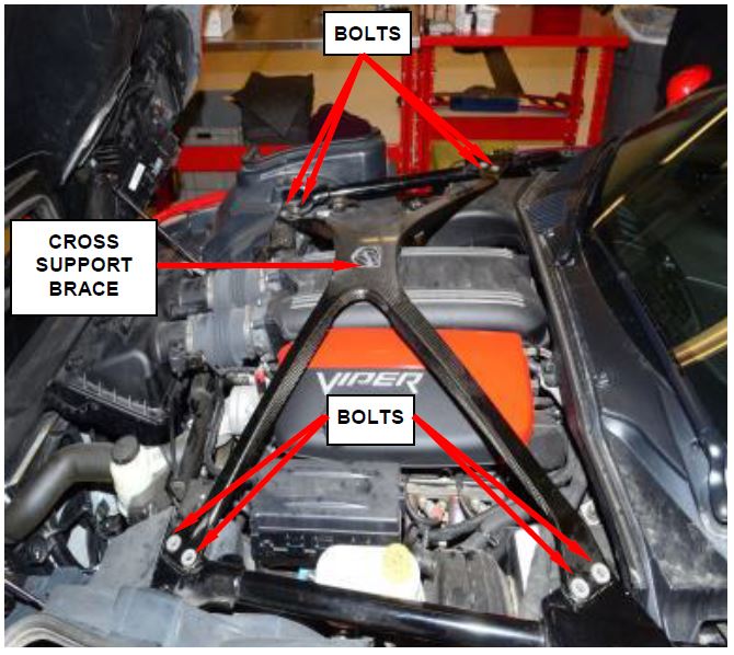
- Remove the eight bolts that secure the cross support brace. Remove and save the cross brace (Figure 1).
Figure 1 – Cross Brace
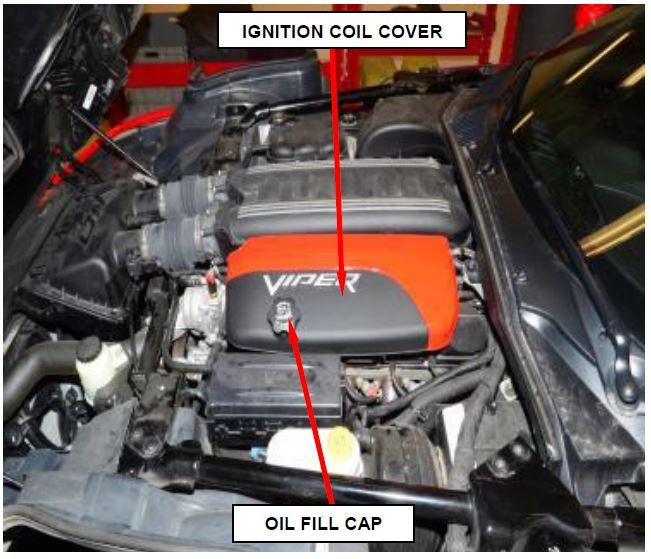
- Remove and discard the oil fill cap (Figure 2).
- Remove and discard the left side ignition coil cover (Figure 2).
Figure 2 – Ignition Coil Cover
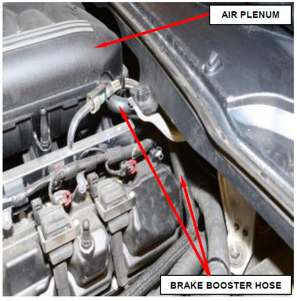
- Disconnect the brake booster hose retaining clip from the cylinder head cover and the hose from the air plenum. Position the hose to the side (Figure 3).
Figure 3 – Brake Booster Hose
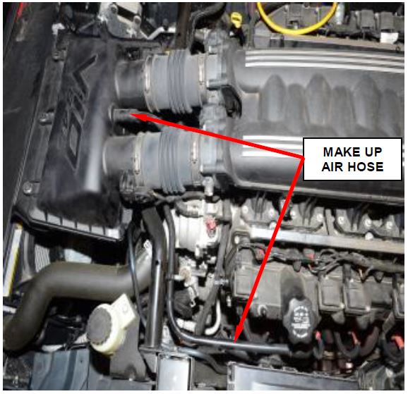
- Remove and discard the Make Up Air hose (MUA) (Figure 4).
Figure 4 – Make Up Air Hose
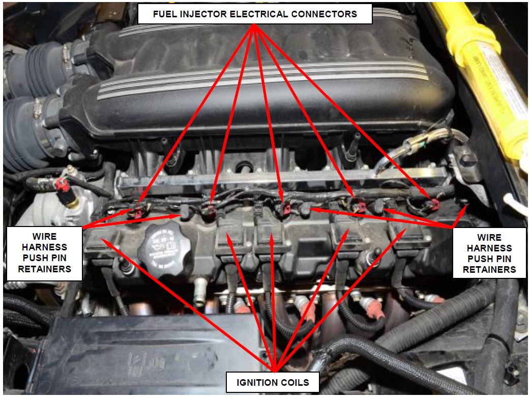
- Disconnect the five ignition coil electrical connectors.
- Disconnect the five fuel injector electrical connectors (Figure 5).
- Remove the five ignition coils from the cylinder head cover and position to the side (Figure 5).
- Release the five wire harness push pin retainers and position the wire harness to the side (Figure 5).
Figure 5 – Electrical Connectors
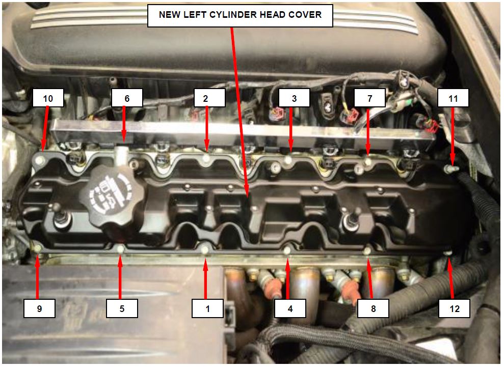
- Remove and save the twelve left cylinder head cover bolts. Remove and discard the left cylinder head cover (Figure 6).
- Place the NEW left cylinder head cover onto the left cylinder head.
- Install and tighten the twelve cylinder head cover bolts and tighten to 80 in. lbs. (9 N·m) in the sequence shown (Figure 6).
- Install the five ignition coils to the cylinder head cover and tighten the screws securely (Figure 5).
- Position the wire harness to the cylinder head cover and install the five wire harness push pin retainers (Figure 5).
Figure 6 – Left Cylinder Head Cover Tightening Sequence
- Connect the five fuel injector electrical connectors (Figure 5).
- Connect the five ignition coil electrical connectors (Figure 5).
- Connect the brake booster hose retaining clip to the cylinder head cover and the hose to the air plenum (Figure 3).
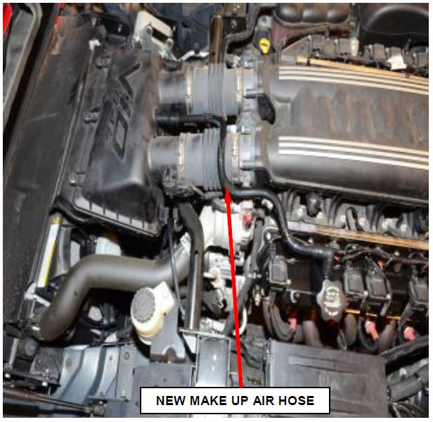
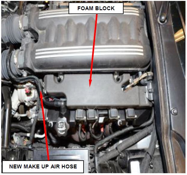
- Install the NEW Make Up Air hose (MUA) as shown (Figure 7).
- Install the supplied foam block over the fuel rail as shown (Figure 8).
NOTE: The foam block is a slip fit to the engine and its components. The left ignition coil cover contains and secures the foam block when installed.
Figure 7 – New Make Up Air Hose
Figure 8 – Foam Block
NOTE: Make sure the rubber coil cover isolators are in place prior to installing the engine covers.
- Install the NEW left ignition coil cover (Figure 2).
- Install the cross support brace and tighten the bolts to 15 ft. lbs. (20 N·m) (Figure 1).
- Connect the negative battery cable.
- Close the trunk lid, hood and return the vehicle to the customer.
NOTE: Inform the customer that the oil filter analysis results should take about one week. Vehicles found with abrasive debris in the engine oil filter must have the engine long block replaced. Also the engine oil cooler and all related components must be replaced.
- After approximately one week you will receive the oil filter analysis results. Viper Warranty Engine Center (VWEC) will email the results to the dealer (email address provided on the I-sheet).
- If the oil filter analysis indicates oil contamination, contact the customer and inform the customer that an engine long block kit must be installed then continue with Section C. Remove Engine Long Block when the vehicle returns.
- If the oil filter analysis indicates no oil contamination, contact the customer and inform them that there is no oil contamination and an engine long block kit is not required, the repair is complete.
C. Remove Engine Long Block
NOTE: When removing the engine, care should be taken not to damage the windshield or the finish on the intake manifold, coil covers, and head covers. Cover the parts with a suitable material.
- Use the following steps to release the fuel pressure.
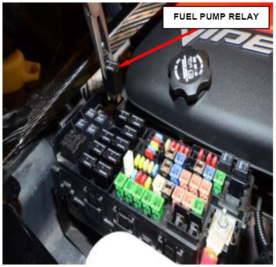
a. Remove Fuel Pump relay from the Power Distribution Center (PDC). For location of relay, refer to label on underside of PDC cover (Figure 9).
b. Start and run engine until it stalls.
Figure 9 – Fuel Pump Relay Location
c. Attempt restarting engine until it will no longer run.
d. Turn ignition key to OFF position.
e. Return fuel pump relay to PDC.
f. One or more Diagnostic Trouble Codes (DTC’s) may have been stored in PCM memory due to fuel pump relay removal. Scan tool must be used to erase a DTC.
- Open the trunk lid. Disconnect the battery negative cable.
- Remove the shift knob and shift bezel then cut the tie strap securing the rubber weather boot.
- Use the following steps to remove the hood.
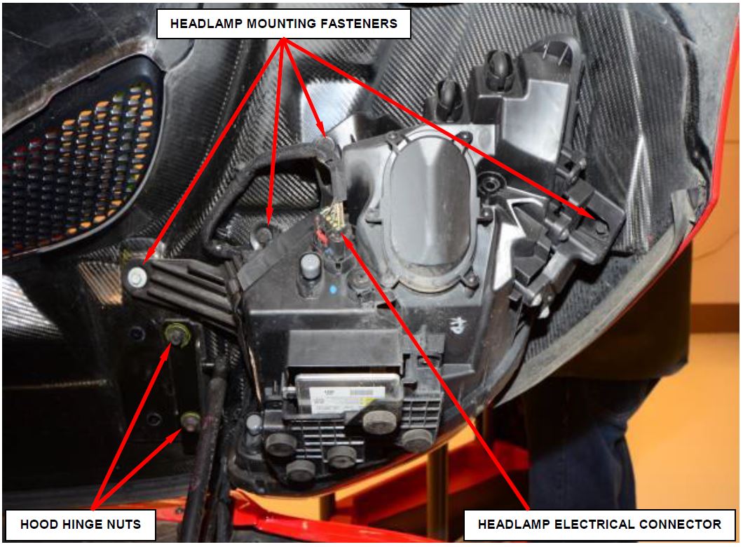
a. Disconnect the right and left headlamp electrical connectors from the headlamp assemblies (Figure 10).
b. Remove the four right and left side headlamp mounting fasteners (Figure 10).
c. Remove the headlamp assemblies.
d. Release the five wire harness retaining clips from the hood.
e. Mark the position of the nuts to the hinge to aid in installation.
f. Remove the four right and left side nuts attaching the hinges to the hood (Figure 10).
g. With the aid of an assistant, remove the hood from vehicle.
Figure 10 – Headlamp Assembly (Right Side Shown)
- Use the following steps to remove the air cleaner housing.
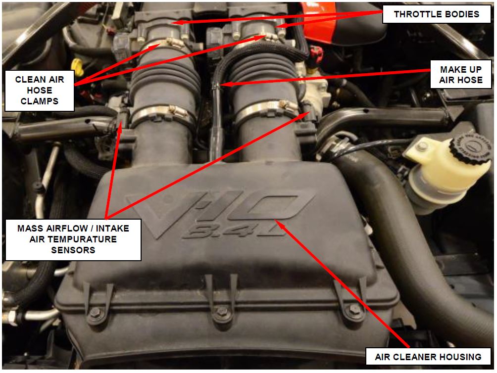
a. Disconnect the Make Up Air hose from the air cleaner housing (Figure 11).
b. Disconnect the mass air flow/intake air temperature sensors electrical connectors (Figure 11).
c. Loosen the clean air hose clamps from the throttle bodies (Figure 11).
d. Remove the air cleaner housing retainers.
e. Remove the air cleaner housing.
Figure 11 – Air Cleaner Housing
WARNING: Do not remove the radiator pressure cap, cylinder block drain plugs or loosen the radiator draincock with the cooling system hot and under pressure. Serious burns from engine coolant can occur.
NOTE: When servicing the cooling system, it is essential that coolant does not drip onto the accessory drive belt and/or pulleys. Shield the belt with shop towels before working on the cooling system. If coolant contacts the belt or pulley, flush both with clean water.
a. Remove the coolant bottle pressure cap.
b. Raise the vehicle on a hoist.
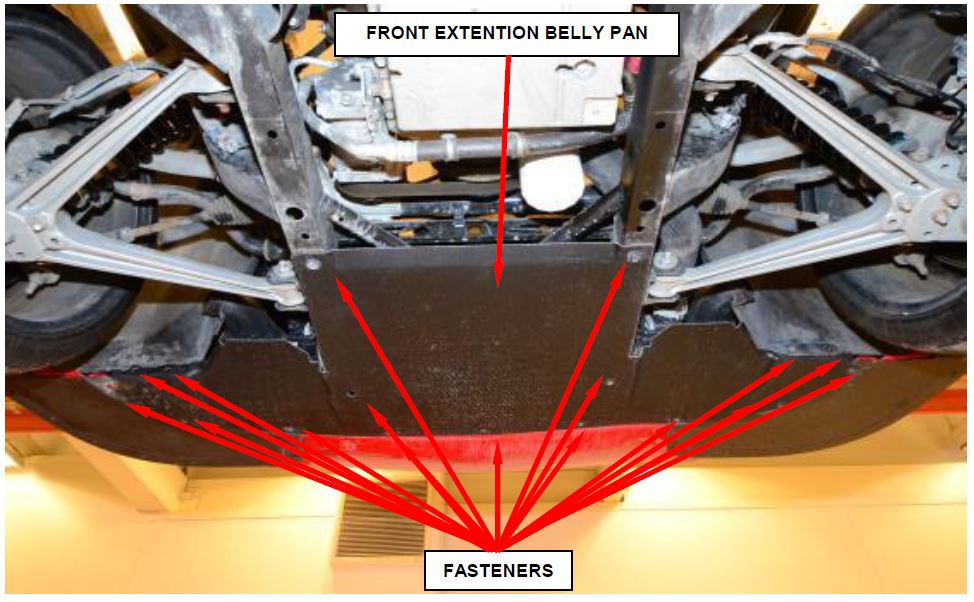
c. Remove the front extension belly pan (Figure 12).
d. Open the radiator draincock located at the lower left side of radiator and drain the coolant into a suitable pan.
e. Remove the engine block drain plug(s).
Figure 12 – Front Extension Belly Pan
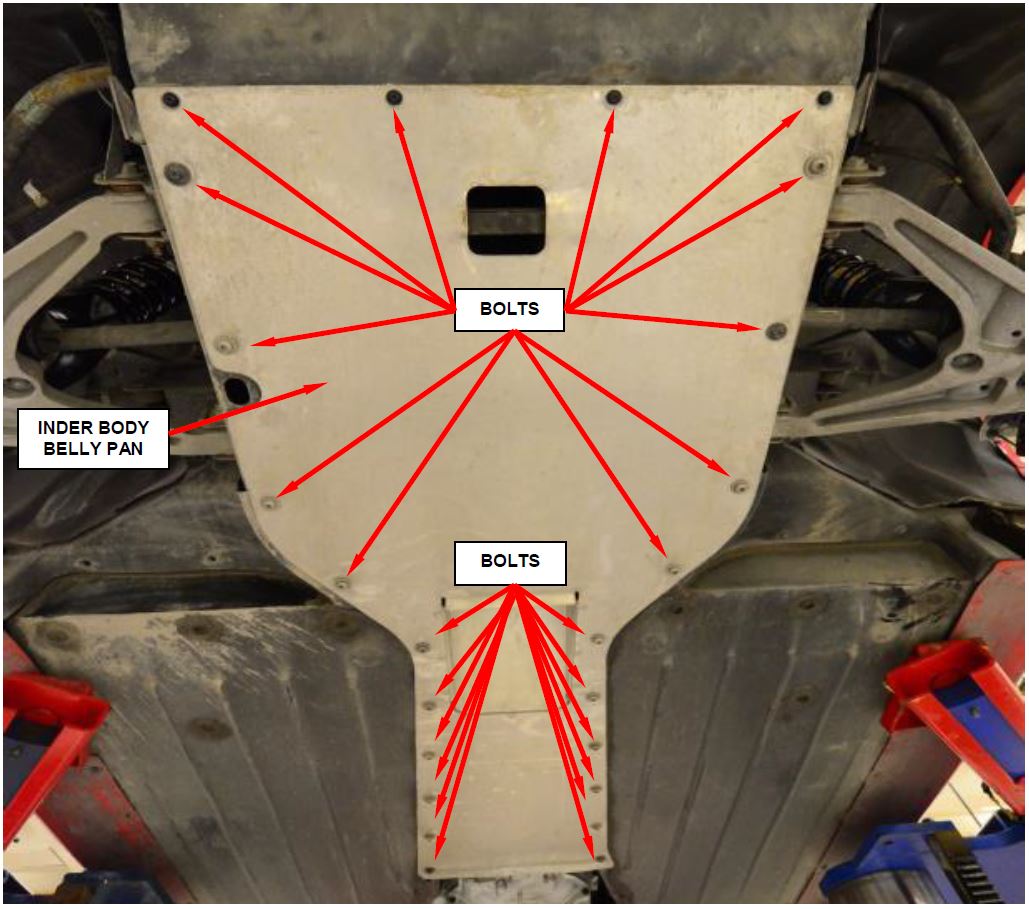
- Remove and save the twenty four under body belly pan bolts and remove the pan (Figure 13).
- Lower the vehicle.
Figure 13 – Under Body Belly Pan
- Discharge the air conditioning system using a suitable refrigerant recovery machine using the manufacturer’s instructions.
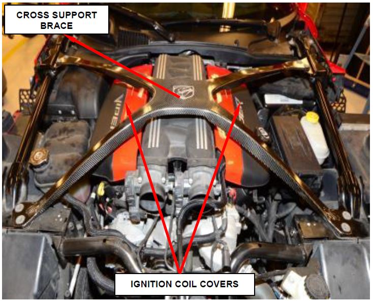
- Remove and save the cross support brace (Figure 14).
Figure 14 – Cross Support Brace
- Remove and save the right and left side ignition coil covers (Figure 14).
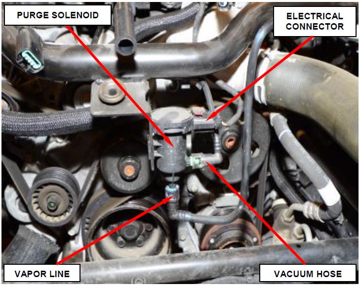
- Disconnect the purge solenoid electrical connector, vapor line and vacuum hose (Figure 15).
Figure 15 – Purge Solenoid
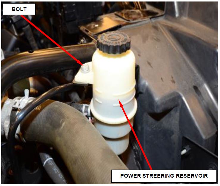
- Remove and save the bolt securing the power steering reservoir and position the reservoir to the side (Figure 16).
Figure 16 – Power Steering Reservoir
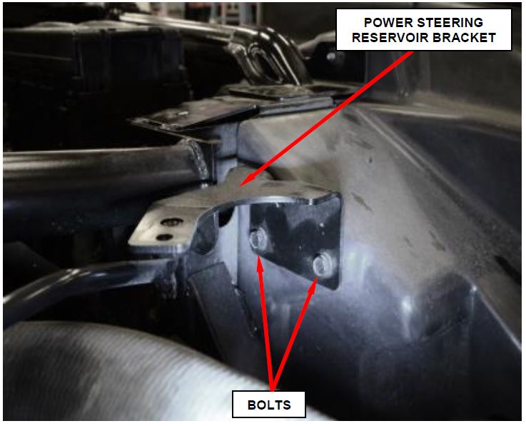
- Remove and save the two bolts securing the power steering reservoir bracket and remover the bracket (Figure 17).
Figure 17 – Power Steering Reservoir Bracket
- Remove all wire harness and hose retaining clips from the front strut tower brace.
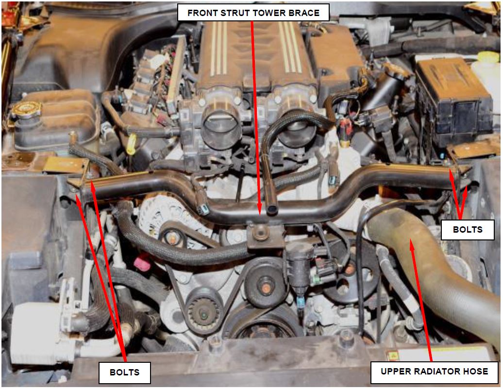
- Remove the four front strut tower brace retaining bolts and remove the brace (Figure 18).
- Remove the upper radiator hose from the engine (Figure 18).
Figure 18 – Front Strut Tower Brace
- Use the following steps to remove accessory drive belt.
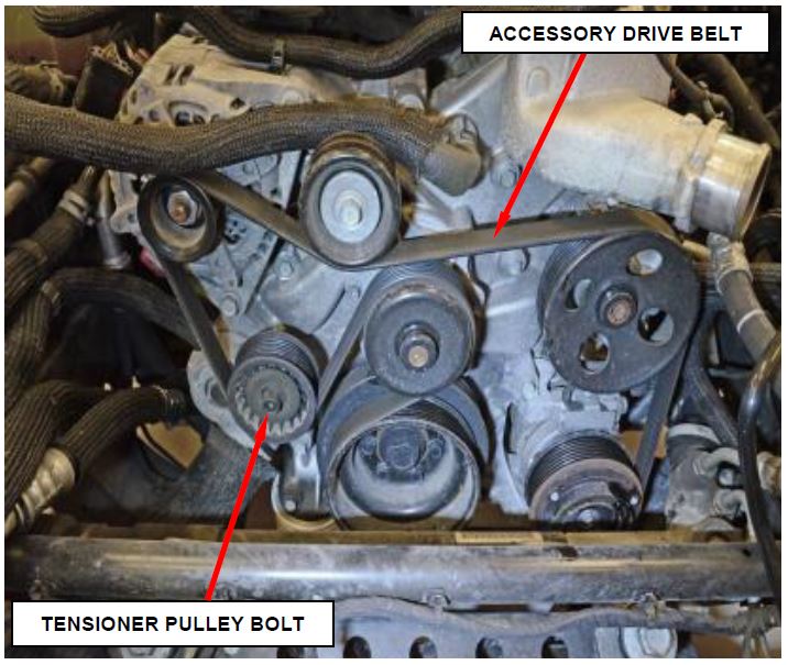
a. Release the belt tension by rotating the accessory drive belt tensioner counterclockwise with a 15 mm wrench on the tensioner pulley bolt. Rotate belt tensioner until belt can be removed from pulleys (Figure 19).
b. Remove and save the accessory drive belt.
c. Gently release accessory drive belt tensioner.
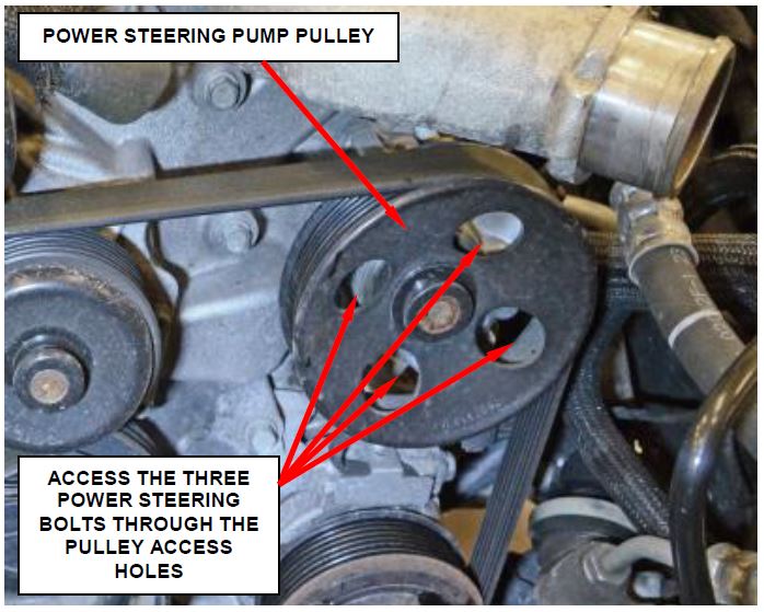
- Remove and save the three bolts that secure the power steering pump and remove the power steering pump. Do not disconnect lines, position aside (Figure 20).
Figure 19 – Accessory Drive Belt
Figure 20 – Power Steering Pump
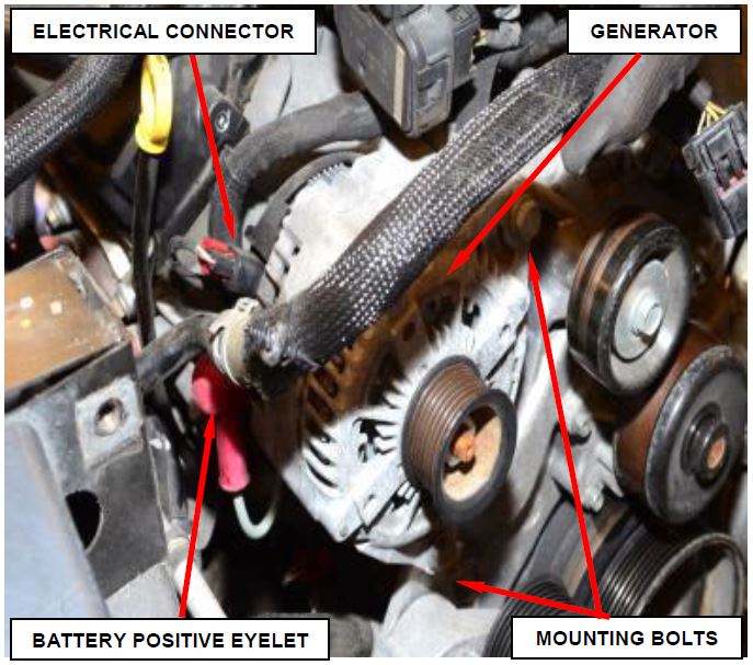
- Use the following steps to disconnect and remove the generator (Figure 21).
a. Disconnect the generator electrical connector (Figure 21).
b. Disconnect the battery positive eyelet from the generator (Figure 21).
c. Remove the two mounting bolts and remove the generator (Figure 21).
Figure 21 – Generator
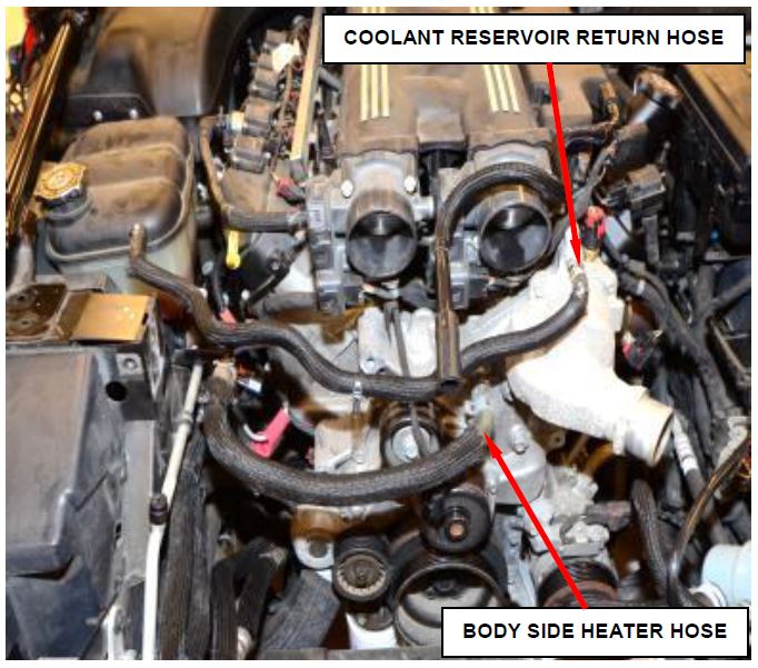
- Disconnect the coolant reservoir return hose from the engine and position aside (Figure 22).
- Disconnect the body side heater hose from the engine and position aside (Figure 22).
Figure 22 – Coolant Reservoir Return Hose
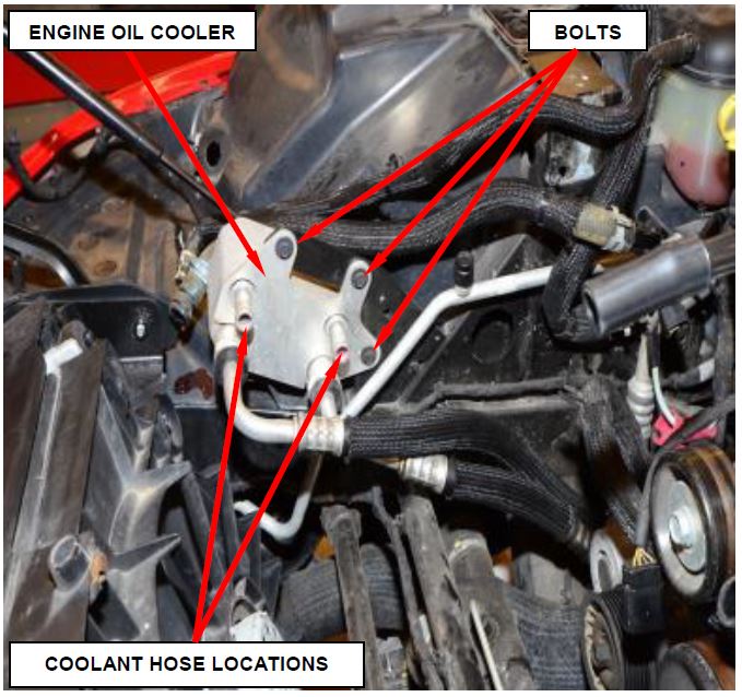
- Disconnect the two coolant hoses from the engine oil cooler and position aside (Figure 23).
- Remove and save the three bolts securing the engine oil cooler to the oil cooler mounting bracket and position the cooler with the oil cooler lines attached to the engine (Figure 23).
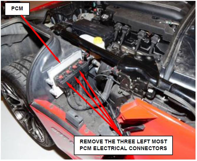
- Remove and save the Powertrain Control Module (PCM) electrical connector cover.
- Disconnect the three Powertrain Control Module (PCM) electrical connectors (Figure 24).
- Release the wire harness retaining clips from the body and position the PCM connectors to the engine.
Figure 23 – Engine Oil Cooler
Figure 24 – PCM Electrical Connectors
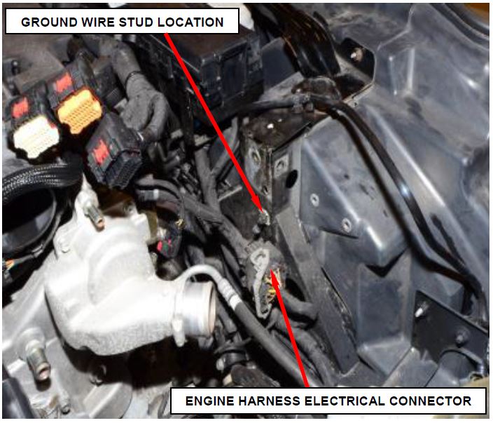
- Remove the ground wire from the stud at the left side frame rail (Figure 25).
- Disconnect the engine harness electrical connector (Figure 25).
Figure 25 – Ground Wire
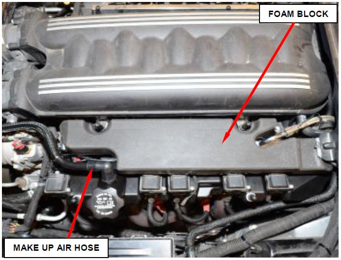
- Remove and save the foam block (Figure 26).
- Remove and save the Make Up Air (MUA) hose (Figure 26).
Figure 26 – Foam Block / MUA Hose
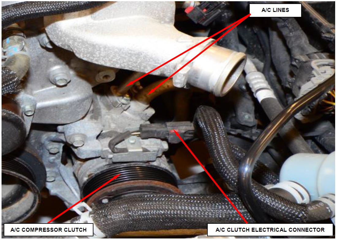
- Disconnect the A/C clutch electrical connector (Figure 27).
- Remove the bolts that secure the A/C suction line and the A/C discharge line to the A/C compressor. Plug the holes in A/C compressor and A/C lines to prevent debris from entering A/C system (Figure 27).
Figure 27 – A/C Lines
- Use the following steps to remove the windshield wiper arms.
a. Lift the wiper arm to its over- center position to hold the wiper blade off of the glass and relieve the spring tension on the wiper arm to pivot shaft connection.
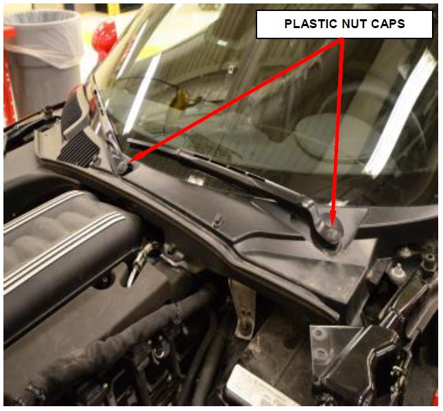
b. Carefully pry the plastic nut cap off of the nut on the pivot end of the wiper arm (Figure 28).
Figure 28 – Wiper Arms
c. Remove the nut that secures the wiper arm to the wiper pivot shaft.
CAUTION: The use of a battery terminal puller when removing the wiper arm is NOT recommended as this may damage the wiper arm.
d. Use a slight rocking action to disengage the wiper arm pivot end from the pivot shaft and remove the wiper arms
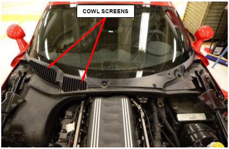
- Remove the cowl screen screws and remove the cowl screens (Figure 29).
Figure 29 – Cowl Screens
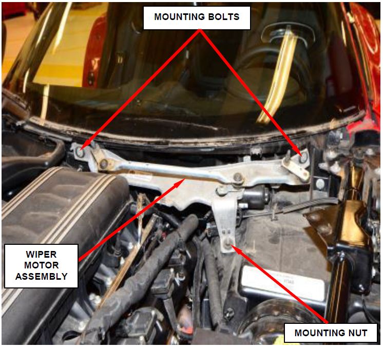
- Remove the two wiper motor assembly mounting bolts and one mounting nut then remove the wiper motor assembly (Figure 30).
- Disconnect the wiper motor electrical connector and remove the wiper motor assembly.
Figure 30 – Wiper Motor Assembly
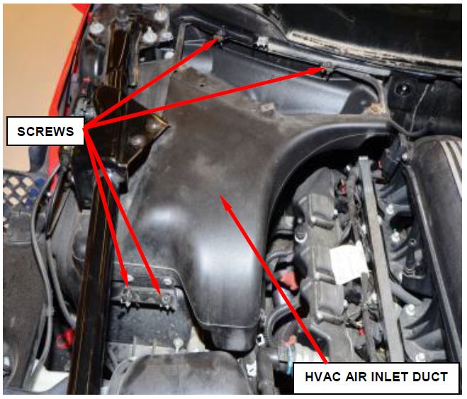
- Remove the four screws securing the HVAC air inlet duct and remove the HVAC air inlet duct (Figure 31).
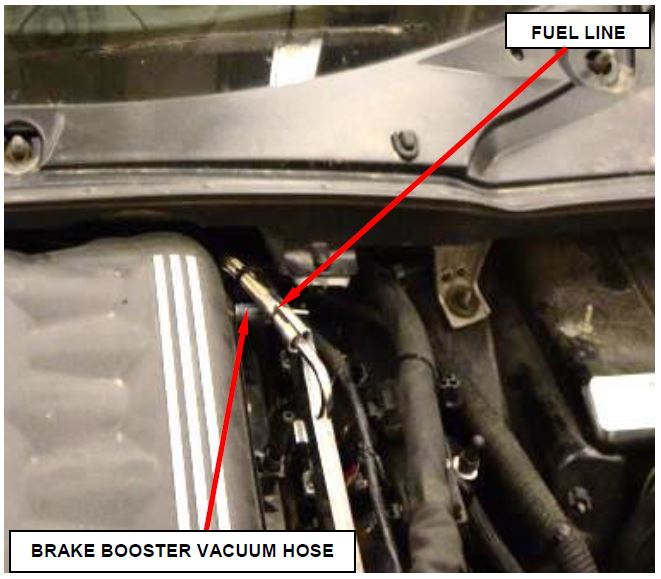
- Disconnect the fuel line (Figure 32).
- Disconnect the brake booster vacuum supply hose at the intake manifold (Figure 32).
Figure 31 – HVAC Air Inlet Duct
Figure 32 – Fuel Line
- Use the following steps to remove the left and right side sill panels.
NOTE: Left side shown, right side typical.
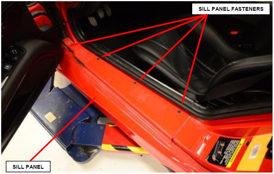
a. Open the door and remove the four fasteners from the sill trim panel (Figure 33).
b. Raise and support the vehicle.
Figure 33 – Sill Panel Fasteners
c. Remove the rear tire and wheel assemblies.
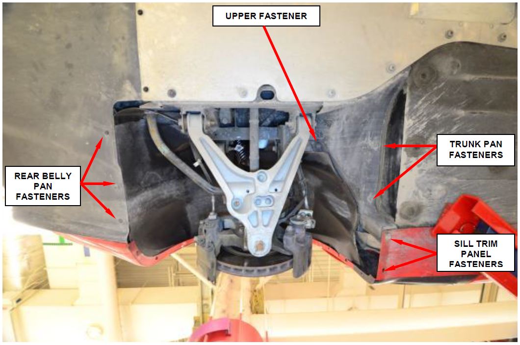
d. Remove the two fasteners to the trunk pan (Figure 34).
e. Remove the two sill trim panel fasteners (Figure 34).
f. Remove the upper fastener from the rear wheelhouse splash shield (Figure 34).
g. Remove the three rear belly pan fasteners (Figure 34).
Figure 34 – Sill Trim Fasteners
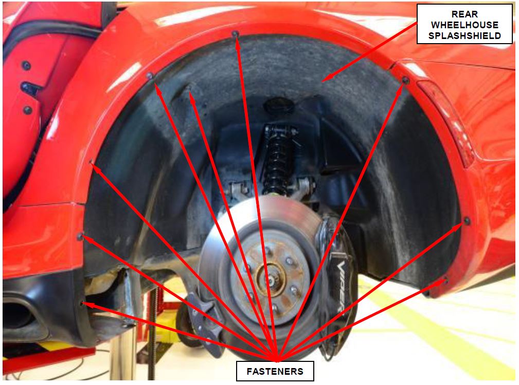
h. Remove the fasteners securing the rear fascia (Figure 35).
i. Route the rear wheelhouse splash shield off of the outer edges.
j. Lower the rear wheelhouse splash shield and route the rear brake air duct from the rear wheelhouse splash shield.
k. Remove the rear wheelhouse splash shield from the vehicle.
Figure 35 – Rear Wheelhouse Splash Shield
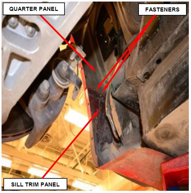
l. Remove and save the two fasteners securing the sill trim panel to the quarter panel (Figure 36).
Figure 36 – Sill Trim Panel
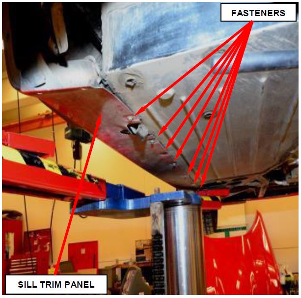
m. Remove and save the seven fasteners from the bottom sill trim panel (Figure 37).
Figure 37 – Sill Trim Panel
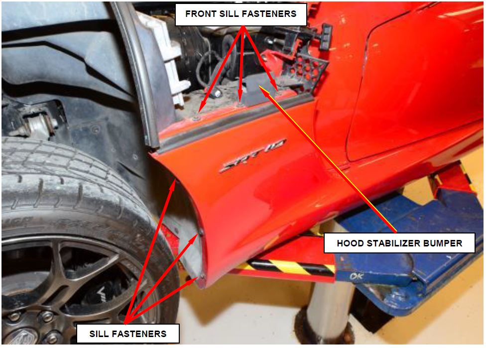
n. Mark the location of the front sill fasteners, for proper alignment during installation the remove and save the three front sill fasteners (Figure 38).
o. Remove and save the three front wheelhouse splash shield to sill fasteners (Figure 38).
p. Remove and save the fastener from the hood stabilizer bumper (Figure 38).
q. With the help of an assistant, slide the sill trim panel outward and remove from the vehicle.
- Raise the vehicle on hoist.
Figure 38 – Front Sill Fasteners
- Disconnect the exhaust system at left and right exhaust manifolds. Do not reuse V-band clamps.
- Remove the left and right catalytic converter support hanger bracket bolts. Position the catalytic converters away from manifolds.
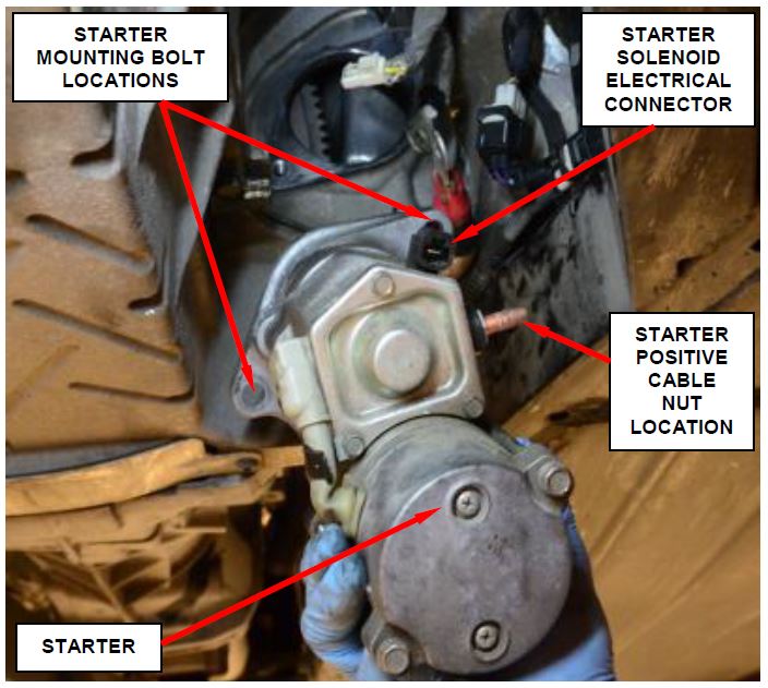
- Disconnect the starter solenoid electrical connector (Figure 39).
- Remove the starter positive cable nut and remove the cable (Figure 39).
- Remove the two starter mounting bolts and remove the starter (Figure 39).
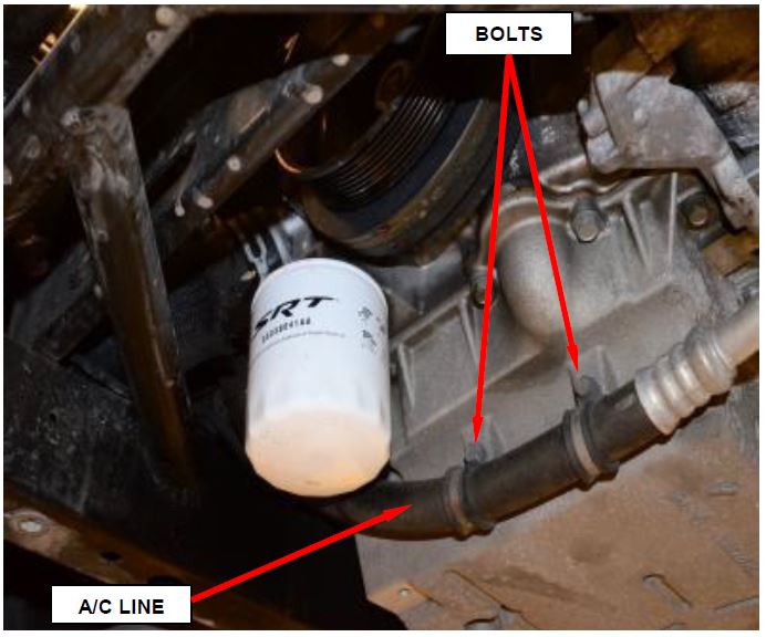
- Remove the two bolts securing the A/C line to the oil pan (Figure 40).
- Remove the lower radiator hose from the engine.
- Using a suitable jack stand, support the engine.
Figure 39 – Starter
Figure 40 – A/C Line to Oil Pan
- Use the following steps to remove the transmission.
CAUTION: The engine must be supported by a brace at the rear of the engine. Do not allow the engine to rest on the spark plug and exhaust flange or damage may occur.
NOTE: Mark an installation reference line across pinion yoke and drive shaft.
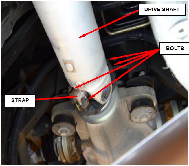
a. Remove and discard the universal joint bolts and straps from pinion yoke and slide propeller shaft yoke out of the transmission. Remove drive shaft (Figure 41).
Figure 41 – Drive Shaft
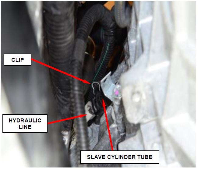
b. Disengage the clip holding clutch hydraulic line to the slave cylinder tube (Figure 42).
c. Pull the hydraulic coupling from the slave cylinder tube. Cover the end of coupler with suitable cap-plug (Figure 42).
Figure 42 – Slave Cylinder
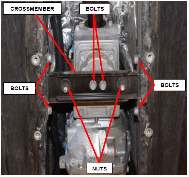
d. Raise the engine/transmission slightly with a support stand. Remove the transmission crossmember and mounting bolts/nuts (Figure 43).
NOTE: Do not allow the engine/transmission assembly to hang freely.
e. Slightly lower the engine/transmission with the support stand.
Figure 43 – Transmission Crossmember
f. Remove isolator/shifter handle from the shifter tower with crow-foot wrench.
g. Remove reverse lamp switch, reverse lockout solenoid and skip shift solenoid harness connectors and retainers from transmission.
h. Position a transmission jack under the transmission.
i. Secure the transmission to the transmission jack using a suitable safety chain.
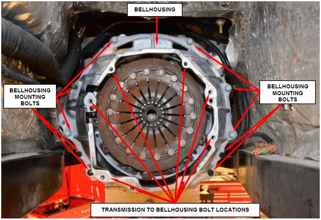
j. Remove the four bolts holding the left side of the transmission to the bellhousing (Figure 44).
k. Remove the four bolts holding the right side of the transmission to the bellhousing (Figure 44).
l. Slide the transmission back so that the input shaft clears the bellhousing.
m. Disconnect the oxygen sensor electrical connectors from the bellhousing and position the harness away from the body.
n. Lower the transmission.
- Remove and save the bellhousing mounting bolts and position the bellhousing away from the engine. The bellhousing remains in the vehicle (Figure 44).
- Install suitable support to the rear of the engine and remove the support
Figure 44 – Bellhousing Bolts
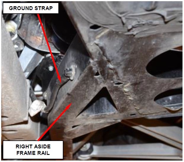
- Disconnect the ground strap from the right side frame rail (Figure 45).
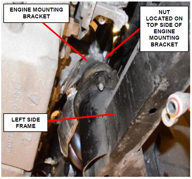
- Remove the left and right engine mount to engine mount bracket nuts (Figure 46).
- Lower the vehicle.
Figure 45 – Ground Strap
Figure 46 – Engine Mount Bracket Nuts (Left Side Shown)
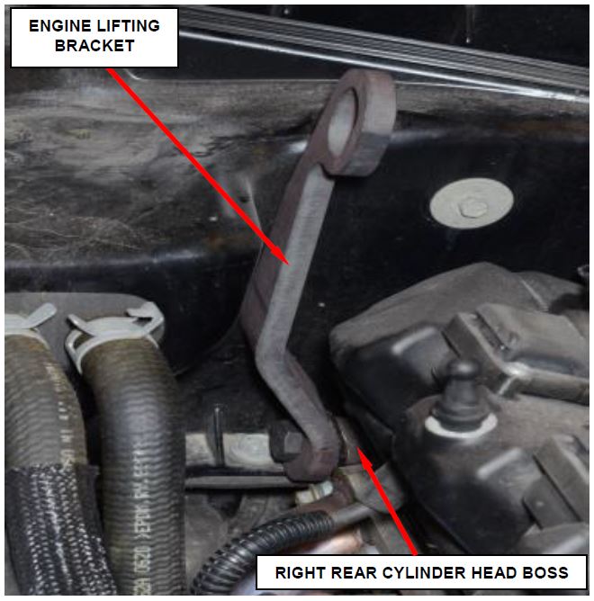
- Install the Engine Lifting Bracket, Rear 10034-2 to the right rear cylinder head boss (Figure 47).
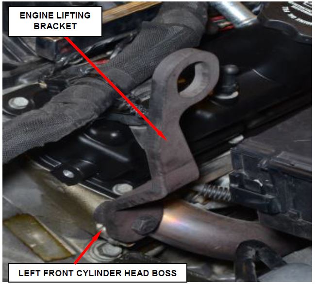
- Install the Engine Lifting Bracket, Front 10034-1 to the left front cylinder head boss (Figure 48).
Figure 47 – Right Rear Cylinder Head Boss
- Attach an appropriate chain to the engine lifting brackets. Remove the engine with an engine hoist.
- Continue with Section D. Prepare NEW Engine Long Block for Installation.
Figure 48 – Left Front Cylinder Head Boss
D. Prepare NEW Engine Long Block for Installation
- Remove the engine long block from the shipping crate.
- Transfer the right and left exhaust manifolds from the original engine block to the NEW engine long block using NEW exhaust manifold gaskets. Tighten the attaching fasteners to 21 ft. lbs. (29 N·m).
- Transfer the spark plug wires from the original engine block to the NEW engine long block.
- Transfer the engine harness from the original engine block to the NEW engine long block.
- Transfer oil level indicator and tube from the original engine block to the NEW engine long block. Tighten the attaching fastener securely.
- Transfer belt tensioner from the original engine block to the NEW engine long block. Tighten the mounting nut to 30 ft. lbs. (41 N·m).
- Transfer idler pulley from the original engine block to the NEW engine long block. Tighten the mounting nut to 40 ft. lbs. (54 N·m).
- Transfer A/C compressor from the original engine block to the NEW engine long block. Tighten the bolts that secure the A/C compressor to the cylinder block to 17 ft. lbs. (23 N·m).
- Transfer the clutch disc and the pressure plate assembly from the original engine block to the NEW engine long block.
a. Insert Clutch Alignment Tool 10018 into pilot bearing.
b. Install the clutch disc over the clutch alignment tool and up against flywheel.
c. Install the pressure plate assembly over the clutch alignment tool and up against the flywheel with index marks aligned and onto the dowel pins next to each bolt location. Assure all clutch component alignment paint marks are lined up before being bolted down.
NOTE: If a new clutch or flywheel is being installed, align the cover balance spot as close as possible to the flywheel balance orange spot.
NOTE: Do Not reuse the original bolts when installing the clutch cover. Replace the bolts whenever the clutch is removed.
d. Install the NEW bolts to hold the clutch cover plate to the flywheel.
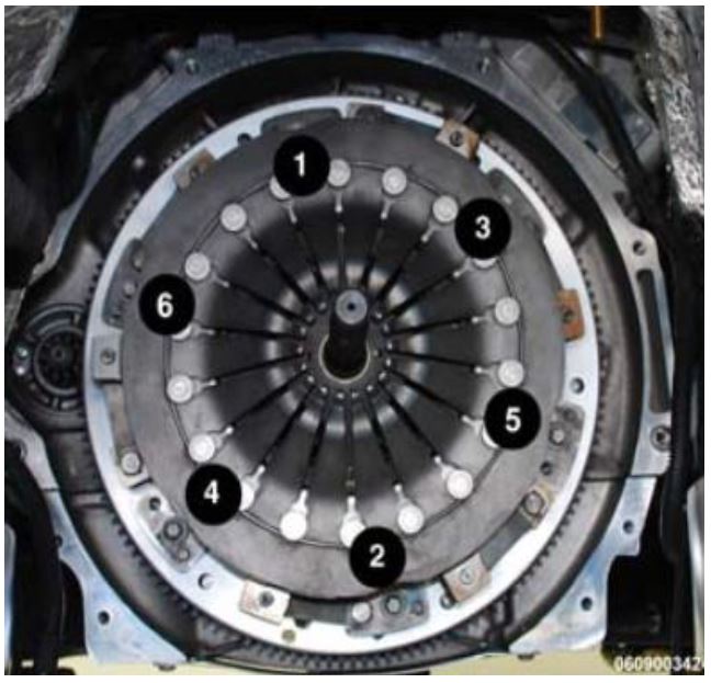
A few turns at a time, tighten the bolts (1 through 6) to hold the clutch cover plate to the flywheel in the pattern illustrated until bolts are seated. Verify that the tool 10018 slides smoothly out and back into the pilot bearing. If not, loosen the cover plate bolts and reposition the clutch discs and tighten the bolts again in the same fashion.
NOTE: If the tool 10018 does not slide out and in smoothly the transmission will not seat against the bellhousing during installation.
Figure 49 – Bellhousing Torque Sequence
f. Then tighten the bolts in the same pattern to 55 ft. lbs. (75 N·m).
g. Remove the clutch disc alignment tool 10018.
- Transfer the flywheel inspection/dust cover from the original engine block to the NEW engine long block.
- Transfer the throttle bodies from the original engine block to the NEW engine long block. Tighten the throttle body bolts in a mandatory torque criss – cross pattern sequence to 71 in. lbs. (8 N·m).
- Transfer the motor mount brackets, heat shields and the engine ground strap (right side only) from the original engine block to the NEW engine long Tighten the motor mount bracket nuts to 45 ft. lbs. (61 N·m).
- Transfer the coolant line for the oil cooler from the original engine block to the NEW engine long block.
- Install the NEW engine oil cooler lines to the NEW engine long block
- Attach the NEW engine oil cooler to the NEW engine oil cooler lines.
- Continue with Section E. Install Engine Long Block.
E. Install Engine Long Block
- Install the Engine Lifting Bracket, Rear 10034-2 to the right rear cylinder head boss of the NEW engine long block (Figure 48).
- Install the Engine Lifting Bracket, Front 10034-1 to the left front cylinder head boss of the NEW engine long block (Figure 47).
- Attach an appropriate chain to the engine lifting brackets. Attach an engine hoist and lower the NEW engine long block into the engine compartment.
- Install the engine mount isolator nuts and tighten to 45 ft. lbs. (61 N·m) (Figure 46).
- Remove the engine lift brackets from the engine and remove the engine hoist
- Raise the vehicle on hoist.
- Install a suitable jack stand to support the engine.
- Install the ground strap to the right side frame rail and tighten securely (Figure 45).
- Position the harness to the bellhousing and connect the oxygen sensor electrical connectors.
- Install the bellhousing to the NEW engine long block. Tighten the bolts to 40 ft. lbs. (54 N·m) (Figure 44).
- Use the following steps to install the transmission.
a. While guiding the transmission around obstacles, lift the transmission into the underbody tunnel until it aligns with the opening in the bellhousing.
b. Slide transmission into the clutch until it is seated against the bellhousing.
c. Install the eight transmission bolts and tighten to 40 ft. lbs. (54 N·m).
d. Connect the reverse lamp switch, reverse lockout solenoid and skip shift solenoid harness connectors to the transmission.
e. Using a crowfoot wrench, install the shift handle on the shift tower.
f. Place the rear crossmember in position under the rear transmission mount (Figure 43).
g. Loosely install the two bolts to hold the crossmember to the rear transmission mount (Figure 43).
h. Install the four bolts to hold the crossmember to the frame. Tighten the bolts to 24 ft. lbs. (33 N·m) (Figure 43).
i. Tighten the crossmember adjustment nuts to 24 ft. lbs. (33 N·m) (Figure 43).
j. Tighten the crossmember the transmission mount bolts to 29 ft. (40 N·m) (Figure 43).
k. Connect the hydraulic clutch quick connector to the clutch release bearing (Figure 42).
l. Install the propeller shaft using the NEW universal joint bolts and straps. Tighten the NEW bolts to 28 ft. lbs. (38 N·m) (Figure 41).
- Install the bolts securing A/C line to oil pan. Tighten the bolts to 80 in. lbs. (9 N·m) (Figure 40).
- Install the starter. Tighten the bolts to 40 ft. lbs. (54 N·m) (Figure 39).
- Position the positive cables onto the starter solenoid post. Tighten the nut to 124 in. lbs. (14 N·m) (Figure 39).
- Connect the starter solenoid electrical connector (Figure 39).
- Connect exhaust system at left and right exhaust manifolds using NEW V-Band clamps. Tighten V-Band clamps to 97 in. lbs. (11 N·m).
- Install the left and right catalytic converter support hanger bracket bolts. Tighten the bolts to 21 ft. lbs. (28 N·m).
- Use the following steps to install the left and right side sill panel.
a. With the help of an assistant, slide the sill trim panel inward into position on the sill panel.
b. Loosely install the front sill panel fasteners (Figure 38).
c. Align the front sill panel fasteners to the marks made during removal and tighten securely (Figure 38).
d. Install the fastener into the hood stabilizer bumper and tighten securely (Figure 38).
e. Install the front wheelhouse splash shield to sill fasteners and tighten to 15 ft. lbs. (20 N·m) (Figure 38).
f. Install the fasteners into the bottom of the sill trim panel and tighten securely (Figure 37).
g. Install the fasteners securing the sill trim panel to the quarter panel and tighten securely (Figure 36).
h. Position the rear wheelhouse splash shield to the vehicle
i. Route the rear brake air duct into the opening in the rear wheelhouse splash shield.
j. Position the rear wheelhouse splash shield into the wheelhouse fully.
k. Install the fasteners securing the rear wheelhouse splash shield and tighten securely (Figure 35).
l. Install the three rear belly pan fasteners (Figure 34).
m. Install the upper fastener to the rear wheelhouse splash shield (Figure 34).
n. Install the two sill trim panel fasteners (Figure 34).
o. Install the two fasteners to the trunk pan (Figure 34).
p. Install the under body belly pan (Figure 13). Tighten the bolts to 18 ft. lbs. (25 N·m).
q. Install the rear tire and wheel assemblies. Tighten to 107 ft. lbs. (145 N·m).
r. Close the radiator draincock and install the front extension belly pan (Figure 12).
s. Lower the vehicle.
t. Open the door and install the fasteners to the sill trim panel (Figure 33).
- Connect the brake booster vacuum supply hose to the intake manifold.
- Connect the fuel line (Figure 32).
- Position the HVAC air inlet duct and install the four screws securing the HVAC air inlet duct. Tighten securely (Figure 31).
- Connect the headlamp and dash wire harness connector to the wiper motor pigtail wire connector.
- Position the wiper motor assembly and install the three wiper motor assembly mounting fasteners. Tighten to 7 ft. lbs. (10 N·m) (Figure 30).
- Install the cowl cover and cowl screens. Tighten the screws securely (Figure 29).
- Install the windshield wiper arms (Figure 28).
- Connect the A/C clutch electrical connector (Figure 27).
- Connect the A/C lines to A/C Tighten the bolts to 17 ft. lbs. (23 N·m) (Figure 27).
- Install the Make Up Air (MUA) hose (Figure 26).
- Install the foam block over the fuel rail (Figure 26).
- Connect the engine wiring harness connector and the ground wire to the stud at the left side frame rail. Tighten the nut to 124 in. lbs. (14 N·m) (Figure 25).
- Connect the wire harness retaining clips to the body and position the Powertrain Control Module (PCM) connectors to the PCM.
- Connect the three PCM connectors (Figure 24).
- Install the PCM electrical connector cover.
- Install the three bolts securing the engine oil cooler to the oil cooler mounting bracket and tighten securely (Figure 23).
- Connect the two heater hoses to the engine oil cooler (Figure 23).
- Connect the coolant reservoir inlet hose to the coolant reservoir (Figure 22).
- Connect the body side heater hose to the engine (Figure 22).
- Install the generator. Tighten the bolts to 35 ft. lbs. (47 N·m) (Figure 21).
- Connect the battery positive eyelet to the generator (Figure 21).
- Connect the generator electrical connector (Figure 21).
- Install the power steering pump. Tighten the three bolts to 18 ft. lbs. (24 N·m) (Figure 20).
- Install the accessory drive belt (Figure 19).
- Install the upper radiator hose (Figure 18).
- Install the front strut tower brace and install strut tower brace retaining bolts then tighten securely (Figure 18).
- Attach all wire harness and hose retaining clips to the front strut tower brace.
- Install the two bolts securing the power steering reservoir bracket and tighten securely (Figure 17).
- Install the bolt securing the power steering reservoir to the bracket and tighten securely (Figure 16).
- Connect the purge solenoid electrical connector, vapor line and vacuum hose (Figure 15).
- Install the right and left side ignition coil covers (Figure 14).
- Install the cross brace. Tighten bolts to 15 ft. lbs. (20 N·m) (Figure 14).
- Install the air cleaner housing assembly (Figure 11).
- Evacuate and recharge air conditioning system using the manufacturer’s instructions.
- Fill the engine cooling system.
- Check the engine crankcase for the proper oil fill level.
NOTE: The engine long block is delivered with the proper oil fill level.
- Install the hood. Tighten nuts to 12 ft. lbs. (16 N·m) (Figure 10).
- Install the headlamp assemblies (Figure 10).
- Install the shift boot and shift lever.
- Use the following steps to bleed the hydraulic clutch system.
a. Check the brake master cylinder reservoir fluid level, if necessary, add D.O.T. 4 brake fluid.
CAUTION: Use only D.O.T. 4 brake fluid. Other fluids are not compatible.
b. Release the retaining clip at the slave cylinder coupling.
c. Separate the line from the slave cylinder enough to create a leak.
d. Slowly actuate the clutch pedal until fluid flows from the open coupling.
e. Snap the slave cylinder coupling together until the retaining clip locks in place.
f. Actuate the clutch pedal several cycles until the slave cylinder releases and applies the clutch.
g. Allow the clutch to rest for a count of 20 to allow the fluid to stabilize.
h. Actuate the clutch to verify proper operation.
i. If necessary, top off the fluid level in the reservoir.
- Connect the battery negative cable. Tighten the nut to 15 ft. lbs. (16 N·m).
NOTE: The Learn Mis-Fire Adaptive Numerator MUST be performed after the engine has been replaced. Follow the instructions on the wiTECH scan tool.
- Start the engine and check for leaks.
- Using the wiTECH scan tool perform the “Pedal and Throttle Learn” procedure. The command is “Learn ETC” and is found under the “Miscellaneous Functions” menu, which in turn is under “PCM”.
- Using the wiTECH scan tool perform the “Learn Mis-Fire Adaptive Numerator” procedure.
- Return the vehicle to the customer.
Complete Proof of Correction Form for California Residents
The R29 portion of this notice, labor operation number 09-R2-91-82, is subject to the State of California Registration Renewal/Emissions Recall Enforcement Program. Complete a Vehicle Emission Recall Proof of Correction Form (Form No. 81-016-1053) and supply it to vehicle owners residing in the state of California for proof that this recall has been performed when they renew the vehicle registration.
Completion Reporting and Reimbursement
Claims for vehicles that have been serviced must be submitted on the DealerCONNECT Claim Entry Screen located on the Service tab. Claims submitted will be used by Chrysler to record Customer Satisfaction Notification service completions and provide dealer payments.
Use the following labor operation numbers and time allowances:
| Labor Operation Number | Time Allowance | |
|---|---|---|
| Change Engine Oil and Install Engine Oil Consumption Kit | 09-R2-91-82 | 1.4 hours |
| Notify Owner and Close R28 | 09-R2-81-82 | 0.2 hours |
| Notify Owner, Remove and Install Engine Long Block and Close R28 |
09-R2-81-83 |
10.9 hours |
Add the cost of the parts package plus applicable dealer allowance to your claim.
NOTE: See the Warranty Administration Manual, Recall Claim Processing Section, for complete claim processing instructions.
Dealer Notification
To view this notification on DealerCONNECT, select “Global Recall System” on the Service tab, then click on the description of this notification.
Owner Notification and Service Scheduling
All involved vehicle owners known to Chrysler are being notified of the service requirement by mail. They are requested to schedule appointments for this service with their dealers. A generic copy of the owner letter is attached.
Enclosed with each owner letter is an Owner Notification postcard to allow owners to update our records if applicable.
Vehicle Lists, Global Recall System, VIP and Dealer Follow Up
All involved vehicles have been entered into the DealerCONNECT Global Recall System (GRS) and Vehicle Information Plus (VIP) for dealer inquiry as needed.
GRS provides involved dealers with an updated VIN list of their incomplete vehicles. The owner’s name, address and phone number are listed if known. Completed vehicles are removed from GRS within several days of repair claim submission.
To use this system, click on the “Service” tab and then click on “Global Recall System.” Your dealer’s VIN list for each recall displayed can be sorted by: those vehicles that were unsold at recall launch, those with a phone number, city, zip code, or VIN sequence.
Dealers should perform this repair on all unsold vehicles before retail delivery. Dealers should also use the VIN list to follow up with all owners to schedule appointments for this repair.
VIN lists may contain confidential, restricted owner name and address information that was obtained from the Department of Motor Vehicles of various states. Use of this information is permitted for this notification only and is strictly prohibited from all other use.
Additional Information
If you have any questions or need assistance in completing this action, please contact your Service and Parts District Manager.
Customer Service / Field Operations
FCA US LLC
CUSTOMER SATISFACTION NOTIFICATION
R28/R29
This notice applies to your vehicle (VIN: xxxxxxxxxxxxxxxxx). Dear: (Name)
At FCA US LLC, we are constantly monitoring the quality of our products and looking for opportunities to improve our
vehicles even after they are sold. Since our customers’ long-term satisfaction is of the utmost importance to us, we are contacting you on important improvements we would like to make to your vehicle. This will be done at no charge to you.
We are recommending the following improvements be performed on certain 2013 through 2014 model year Dodge Viper vehicles.
| The problem is… | The engine cylinder block on your vehicle may have been contaminated with abrasive debris.
Under rare conditions during high-speed right-hand cornering when the engine is at light throttle and high RPM, engine oil can be forced into the Make Up Air hose, resulting in unintended oil consumption. Both of these conditions may compromise engine durability. |
| What your dealer will do… | FCA will repair your vehicle free of charge. To address R28, the oil contamination issue, your dealer will complete a free engine oil & filter change and send the used oil filter to FCA for analysis. If FCA’s analysis of the oil filter is positive for debris, the dealer will contact you to schedule replacement of the engine and related oil cooler components. If a new engine is not required, the dealer will contact you to inform you that you do not need to return to the dealership.
To address R29, the oil consumption issue, your dealer will install an updated oil management system which includes a new valve cover assembly with a relocated make up air (MUA) fitting and new baffle. The work will take about 1½ hours to complete if an engine replacement is not required. If an engine replacement is required, the additional work will take about 11 hours to complete. However, additional time may be necessary depending on service schedules. |
| What you should do… | Please call the SRT Information Center at 855-778 8326 to schedule service at a certified Dodge Viper dealer. If you have questions or concerns which your dealer is unable to resolve, please contact the SRT Information Center at either fcarecalls.com or 1-855-778 8326. |
| California residents… | For the R29 portion of this notice, the State of California requires the completion of emission recall repairs prior to vehicle registration renewal. Your dealer will provide you with a Vehicle Emission Recall Proof of Correction Form after the recall service is performed. Be sure to save this form since
the California Department of Motor Vehicles may require that you supply it as proof that the recall has been performed. |
Please help us update our records by filling out the attached prepaid postcard, if any of the conditions listed on the card apply to your vehicle. If you have further questions go to fcarecalls.com.
If you have already experienced this specific condition and have paid to have it repaired, you may visit www.fcarecallreimbursement.com to submit your reimbursement request online or you can mail your original receipts and proof of payment to the following address for reimbursement consideration: FCA Customer Assistance, P.O. Box 21-8004, Auburn Hills, MI 48321-8007, Attention: Recall Reimbursement. Once we receive and verify the required documents, reimbursement will be sent to you within 60 days. If you’ve had previous repairs and/or reimbursement you may still need to have the recall repair performed on your vehicle.
We apologize for any inconvenience this service may cause to your schedule. FCA is committed to providing our customers with world class quality products, ensuring that you have a positive dealership experience and following up on any issues and concerns that you may have in a timely manner through our Customer Assistance Center. Thank you for being our customer.
Sincerely, Customer Service / Field Operations
FCA US LLC
RC-R28-R29-16
 Loading...
- Mobil 1 FS European Car Formula full synthetic motor oil 0W-40 helps to extend engine life even in severe conditions
- Helps to control oxidation to prevent oil breakdown and maintain excellent viscosity for up to 10,000 miles between oil changes*
- Provides outstanding engine wear protection and performance with uniform synthetic oil molecules for better friction reduction
- Keeps your engine running like new by working to prevent damaging deposits and sludge buildup
- Provides excellent internal engine heat protection (up to 500 degrees F) and low temperature protection (up to -40 degrees F)
- Reduce particulate buildup in diesel particulate filters
- Reduce poisoning of gasoline catalytic converters
- Reduce deposits and sludge buildup to enable long and clean engine life
- Reduce oil aging, allowing extended drain interval protection
- Our most advanced full synthetic 0W-40 engine oil, designed for unbeatable engine protection*
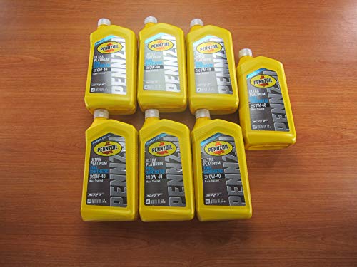
- Pennzoil Ultra Platinum comes with a 20-year, 750,000-mile warranty** to protect your engine and give you peace of mind to drive every mile as hard as you can
- Made with natural gas
- Outstanding performance in extreme temperatures
- Designed for high-performance engines, it helps protect engines from loss of power
- Recommended by world-leading car manufacturers
- Engine protection for the entire drain interval even under extreme pressure
- For use in both gasoline and light duty diesel applications
- Superior engine protection vs conventional and synthetic blend oils
- Better Wear Protection
- Increased Fuel Efficiency
- Better Protection of the Expensive Catalytic Emission System
- Improved Compatibility with Fuels Containing Ethanol
- Advanced protection for European gasoline and diesel vehicles against the four main causes of engine breakdown: wear friction heat and deposits
- Formulated with top-quality anti-wear additives that go beyond industry and OEM standards in European vehicles
- Premium antioxidants and cleaning detergents combine to safeguard against damaging deposits
- Exceptional high/low temperature protection defends your engine no matter the climate or driving conditions
- Meets or exceeds all requirements of API SN, ACEA A3/B3, A3/B4, MB 229.5, MB 229.3, MB 226.5, VW 502.00/505.00, VW 505.01, BMW LL-01, Porsche A40, Renault RN0700 & RN0710, Chrysler A0921, Chrysler MS-12633, Chrysler MS-10725
- Price For: Each Timken OK Load: Not Specified Four-Ball Wear: Not Specified Dropping Point: Not Specified ISO Viscosity Grade: Not Specified Temp. Range: - Item: Motor Oil SAE Grade: 0W-40 Viscosity Index: 186 Series: Mobil 1(TM) Base: Synthetic Size: 1 qt. Viscosity @ 100C: 13.5 Container Type: Bottle Viscosity @ 40C: 75 Pour Point: -54 Degrees C
- Flash Point: 230 Degrees C Country of Origin (subject to change): United States
- ADVANCED MOTOR OIL: Mobil 1 Supercar 0W-40 is an advanced full synthetic, high performance motor oil specifically designed for street and track use in high performance North American sports cars.
- FORMULATED PERFORMANCE: Engineered with a proprietary blend of leading edge components formulated to provide exceptional cleaning power, wear protection, and deliver outstanding overall performance.
- FOR MORE: Mobil 1 Supercar 0W-40 advanced full synthetic motor oil features enhanced frictional properties that help enable improved fuel economy, achieve higher horsepower and reduce engine wear.
- LONGER ENGINE LIFE: Active cleaning agents help enable lower operating temperatures and a resulting longer engine life, while thermal and oxidation stability help to reduce oil aging.
- HIGHLY RECOMMENDED: Mobil 1 Supercar 0W-40 is recommended for GM dexos(R) oil applications, including high performance naturally aspirated, turbo-charged, and super-charged gasoline engines. *
- 4-stroke off-road SXS/UTV engines
- For use in original equipment that requires API SM, JASO MA2
- All temperature/all weather
Last update on 2025-05-08 / Affiliate links / Images from Amazon Product Advertising API
This product presentation was made with AAWP plugin.
