| “This site contains affiliate links for which OEMDTC may be compensated” |
NHTSA Campaign Number: 16V290
Component(s): AIR BAGS
Potential Number of Units Affected: 394,258
Manufacturer: Chrysler (FCA US LLC)
SUMMARY:
Chrysler (FCA US LLC) is recalling certain model year 2007-2010 Jeep
 Wrangler JK vehicles manufactured March 2, 2006, to August 13, 2010.
The clockspring assembly may become contaminated with dust and cause the air bag circuit to fail.
CONSEQUENCE:
Failure of the air bag circuit may prevent the driver’s frontal air bag from deploying in the event of a crash, increasing the risk of injury.
REMEDY:
Chrysler will notify owners, and dealers will replace the clockspring, wheel back cover, and column shroud, free of charge.
Remedy parts are expected to become available in November 2016.
Owners were mailed interim notices on July 5, 2016.
Owners will receive a second notice when remedy parts become available.
Owners may contact Chrysler customer service at 1-800-853-1403.
Chrysler ’s number for this recall is S33.
NOTES:
Owners may also contact the National Highway Traffic Safety Administration Vehicle Safety Hotline at 1-888-327-4236 (TTY 1-800-424-9153), or go to www.safercar.gov.
Check if your Vehicle has a Recall
Revised October 2016
Interim Dealer Service Instructions for:
Safety Recall S33 / NHTSA 16V-290 Airbag Clockspring (Interim Repair)
NOTE: The Inspection procedure and “Special Tool” section have been updated.
Models
| 2007 – 2010 | (JK) | Jeep Wrangler Wrangler |
| IMPORTANT: Some of the involved vehicles may be in dealer used vehicle inventory. Dealers should complete this recall service on these vehicles before retail delivery. Dealers should also perform this recall on vehicles in for service. Involved vehicles can be determined by using the VIP inquiry process. |
Subject
The clockspring on about 393,900 of the above vehicles may ingest dust if the vehicle is subjected to extremely dusty environments. Dust inside the clockspring could compromise airbag circuit(s), causing illumination of the airbag warning light and/or the potential for a non-deployment of the driver airbag during a crash.
Repair
The airbag system must be checked for Diagnostic Trouble Codes (DTC’s).
Vehicles found with clockspring DTC’s must have the DTC-Based Diagnostics in TechCONNECT or wiTECH performed to determine if the clockspring requires replacement.
NOTE: All other airbag system issues are not covered under this recall. The repair costs not related to this recall are the responsibility of the owner unless the vehicle is covered under an extended warranty contract. Please note that the permanent remedy for this issue will still need to be performed once the improved parts are available.
Parts Information
| Part Number | Description |
|---|---|
| 05156106AF | Clockspring |
| 06505656AA | Bolt, Steering Wheel Retaining |
Parts Return
Please make sure to retain this part until the recall claim is paid and the parts disposition has been determined. This recall part will be subject to parts return.
Special Tools
The following special tools are required to perform this repair:
| wiTECH micro pod II |
| Laptop Computer |
| wiTECH Software |
| SRS Load Tool Kit |
| SRS Load Tool Jumper |
Service Procedure
WARNING: TO AVOID SERIOUS OR FATAL INJURY, DISABLE THE SUPPLEMENTAL RESTRAINT SYSTEM (SRS) BEFORE ATTEMPTING THIS SERVICE PROCEDURE. DISCONNECT AND ISOLATE THE BATTERY NEGATIVE (GROUND) CABLE, THEN WAIT TWO MINUTES FOR THE SYSTEM CAPACITOR TO DISCHARGE BEFORE PERFORMING FURTHER SERVICE. THIS IS THE ONLY SURE WAY TO DISABLE THE SRS. FAILURE TO TAKE THE PROPER PRECAUTIONS COULD RESULT IN ACCIDENTAL AIRBAG DEPLOYMENT.
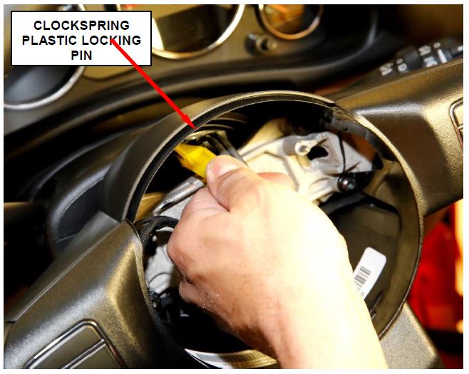
NOTE: A service replacement clockspring is shipped with the clockspring pre-centered and with a molded plastic locking pin installed. This locking pin should not be removed until the steering wheel has been installed on the steering column. If the locking pin is removed before the steering wheel is installed, the clockspring centering procedure must be performed.
NOTE: When a clockspring is installed into a vehicle without properly centering and locking the entire steering system, the Steering Angle Sensor (SAS) data does not agree with the true position of the steering system and causes the Electronic Stability Program (ESP) system to shut down. This may also damage the clockspring without any immediate malfunction. The SAS does not require calibration.
NOTE: Determining if the clockspring/SAS is centered is also possible electrically using the diagnostic scan tool. Steering wheel position is displayed as ANGLE with a range of up to 900 degrees. Refer to the appropriate menu item on the diagnostic scan tool.
NOTE: Before starting this procedure, be certain to turn the steering wheel until the front wheels are in the straight-ahead position and that the entire steering system is locked or inhibited from rotation.
A. Clockspring Diagnosis
NOTE: The wiTECH scan tool must be used to perform this recall. This procedure must be performed with the latest software release level.
- Open the hood. Install a battery charger
 and verify that the charging rate provides 13.2 to 13.5 volts. Do not allow the charger to time out during the flash process (Figure 1). Set the battery charger timer (if so equipped) to continuous charge.
NOTE: Use an accurate stand-alone voltmeter. The battery charger voltmeter may not be sufficiently accurate. Voltages outside of the specified range will cause an unsuccessful flash. If voltage reading is too high, apply an electrical load by activating the park or headlamps and/or HVAC blower motor to lower the voltage.
- Connect the wiTECH micro pod II to the vehicle data link connector.
- Place the ignition in the “RUN” position.
- Open a wiTECH Diagnostic session.
- Starting at the “Select Tool” screen, select the row/tool for the wiPOD device you are using.
- Enter your “User id” and “Password”, then select “Finish”.
- Select the “Next” tab at the bottom of the screen.
- From the “Vehicle View” screen, read and record all Diagnostic Trouble Codes (DTC’s).
NOTE: The supporting documents need to be attached to the claim on the first “RA” submission to aid in quick claim payment. Claims without these supporting documents below will be returned to the dealer as an unsupported request. Dealer may resubmit claim for payment with all required documentation.
A complete copy of the R.O. MUST be attached and include:
- The 3 C’s (Concern, Cause and Correction) must be documented on the repair documentation (i.e. repair order) and the claim.
- A copy of the Vehicle Scan Report (VSR) from wiTECH 1 or 2 to show the Diagnostic Trouble Codes (DTCs) found prior to the repair, MUST be attached to the claim.
See 3 C’s (Concern, Cause and Correction) example below:
Concern: Customer states airbag light is on.
Causes: Confirmed airbag light on. Codes B1B02 – Driver Airbag Squib 1 Circuit Open and B1B06 – Driver Airbag Squib 2 Circuit Open are active. Followed TechCONNECT, DTC-Based Diagnostics for B1B02. Test 2 – Checked and cleaned connectors for the driver airbag Squib Circuits. Test 3 – CHECK THE CLOCKSPRING SQUIB CIRCUITS FOR AN OPEN, with the SRS Load Tool Kit 8443A and SRS Load Tool Jumper 8443-19 connected to the Clockspring C4 connector, code B1B02 was no longer displayed in the scan tool. Test lead to the Clockspring replacement.
Correction: Clockspring was replaced and Airbag verification test performed.
- Technician notes documenting the TechCONNECT diagnostic or wiTECH test procedures leading to the JK clockspring replacement.
- Check for the following DTC’s listed below:
B1B02 Driver Airbag Squib 1 Circuit Open
B1B06 Driver Airbag Squib 2 Circuit Open
B1B01 Driver Airbag Squib 1 Circuit High
B1B05 Driver Airbag Squib 2 Circuit High
P0581 Speed Control Multiplexed Switch #1 High
P0579 Speed Control Multiplexed Switch #1 Performance
P0593 Speed Control Multiplexed Switch #2 High
P0591 Speed Control Multiplexed Switch #2 Performance
P1593 Speed Control Multiplexed Switch #1 / #2 Stuck
U1109 Loss of Communication With SWSM
NOTE: Perform vehicle scan as supporting documentation to be submitted with claim.
NOTE: Document the TechCONNECT diagnostic or wiTECH test procedures leading to the JK clockspring replacement.
NOTE: Document the 3 C’s (Concern, Cause and Correction) to be submitted with claim.
- If diagnostics indicate issue with clockspring as per DTCs noted above, clear all DTC’s and replace the clockspring. Continue with Section B: Clockspring Replacement.
- If the airbag warning lamp is illuminated and none of the DTC’s listed above are present, the issue with the vehicle is not related to this recall.
NOTE: All other airbag system issues are not covered under this recall. The repair costs not related to this recall are the responsibility of the owner unless the vehicle is covered under an extended warranty contract.
SPECIAL NOTE: If the clockspring is replaced at this time, the new clockspring being installed is an interim fix until improved parts become available. The recall will remain in “Open” status and the vehicle must return for the permanent remedy when improved parts become available.
B. Clockspring Replacement
- Place the front wheels in the straight ahead position and inhibit the steering column shaft from rotation.
- Disconnect and isolate the battery negative cable.
WARNING: WAIT TWO MINUTES FOR THE SYSTEM CAPACITOR TO DISCHARGE BEFORE PERFORMING FURTHER DIAGNOSIS OR SERVICE.
- Remove and save the driver airbag module retaining screws.
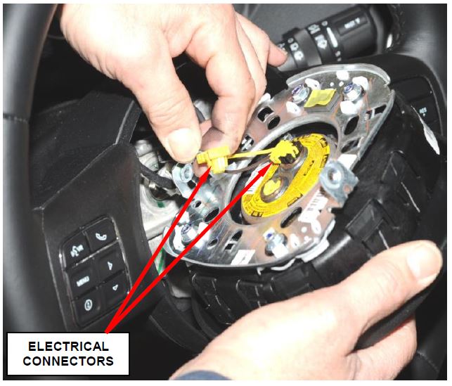
Figure 1 – Airbag Module Electrical Connectors
- Separate the driver airbag module from the steering wheel and disconnect the two airbag electrical connectors (Figure 1) and the one horn electrical connector. Then set the driver airbag module aside.
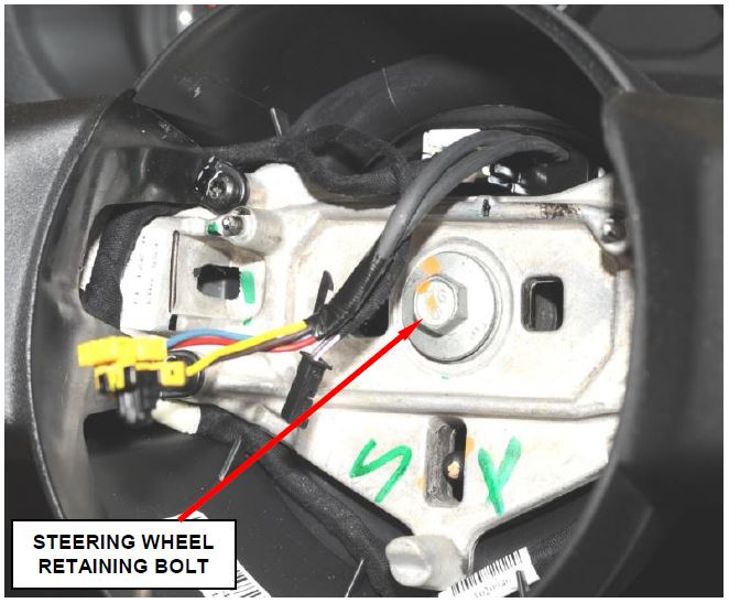
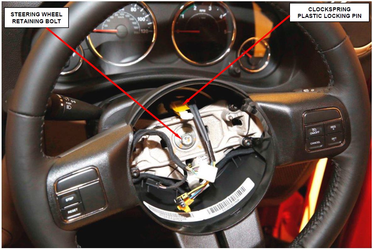
- Remove and discard the steering wheel retaining bolt from the steering shaft (Figure 2).
- Remove and save the steering wheel assembly.
- Move the steering column to the fully lowered position and leave the tilt release lever in the released (down) position.
Figure 2 – Steering Wheel Retaining Bolt
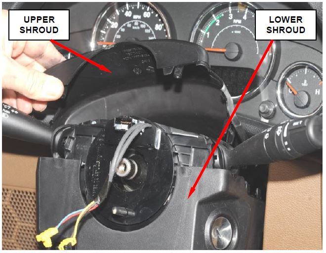
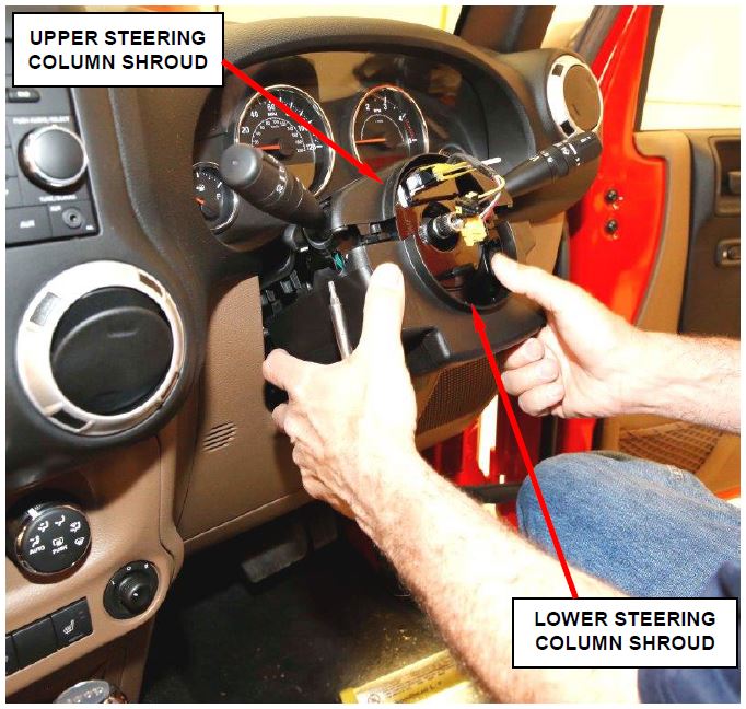
- Remove and save the upper and lower steering column shrouds from the steering column (Figure 3).
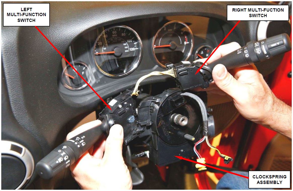
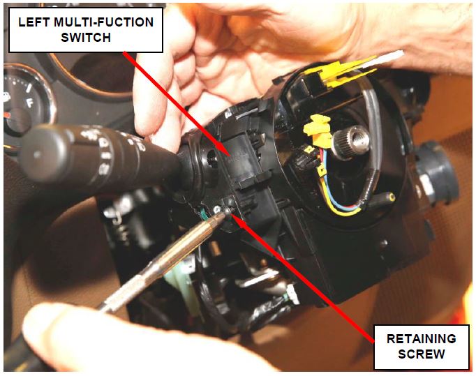
- Remove and save the right and left multi-function switches (Figure 4).
Figure 3 – Upper and Lower Steering Column Shrouds
Figure 4 – Right and Left Multi-Function Switches
- Remove the three screws that secure the clockspring to the steering column lock housing.
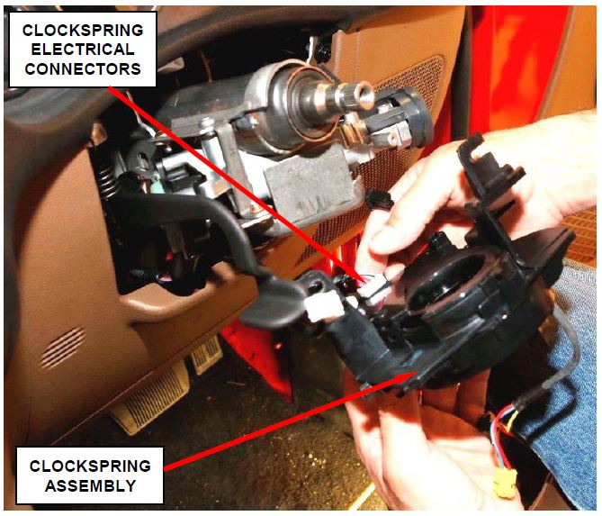
- Pull the clockspring away from the steering column lock housing enough to access and disconnect the three instrument panel wire harness electrical connectors from the receptacles on the back of the clockspring (Figure 5).
Figure 5 – Clockspring Electrical Connections
- Remove the clockspring from the steering column.
- Carefully slide the new clockspring down over the steering column upper shaft far enough to reconnect the three instrument panel wire harness connectors to the receptacles on the back of the clockspring case.
- Connect the three instrument panel wire harness electrical connectors to the receptacles on the back of the clockspring (Figure 5).
- Position the clockspring onto the steering column lock housing.
- Install and tighten the three screws that secure the clockspring to the steering column lock housing in the following sequence:
- Lower Right
- Upper Left
- Upper Right
Tighten the screws to 27 in. lbs. (3 N·m).
CAUTION: Improper sequence when tightening the clockspring mounting screws may result in an audible ticking noise as the steering wheel is rotated.
- Place both multi-function switches onto the new clockspring as an assembly and connect the electrical connector.
- Install the left multi-function switch retaining screw. Tighten the screw to 10 in. lbs. (1 N·m) (Figure 6).
- Install the right multi-function switch retaining screw. Tighten the screw to 10 in. lbs. (1 N·m).
Figure 6 – Multi-Function Switch Retaining Screw (left side switch shown)
- Install the upper and lower steering column shrouds onto the steering column (Figure 7).
- Move the steering column back to the fully raised position and move the tilt release lever back to the locked (up) position.
Figure 7 – Install Steering Column Shrouds
- Install the steering wheel assembly onto the steering column.
Figure 8 – Install New Steering Wheel Retaining Bolt
- Install a new steering wheel retaining bolt finger tight (Figure 11).
- Remove and discard the plastic locking pin that secures the clockspring rotor (Figure 11 and 12).
Figure 9 – Remove Clockspring Locking Pin
- Tighten the new steering wheel retaining bolt to 40 ft. lbs. (54 N·m) (Figure 13).
- Connect the two airbag electrical connectors and the one horn electrical connector to the driver airbag module.
Figure 10 – Tighten Steering Wheel Retaining Bolt to 40 ft. lbs. (54 N·m)
- Install the driver airbag module onto the steering wheel.
- Install the two steering wheel driver airbag module retaining screws. Tighten the screws to 120 in. lbs. (13 N·m).
- Do not connect the negative battery cable at this time. Continue with Section C. Supplemental Restraint System (SRS) Verification Test.
C. Supplemental Restraint System (SRS) Verification Test
NOTE: The wiTECH scan tool must be used to perform this recall. The wiTECH software is required to be at the latest release level before performing this procedure.
- Connect the wiTECH scan tool to the vehicle.
- Turn the ignition switch to the “ON” position, exit the vehicle and close the doors.
- If equipped with an Intelligent Battery Sensor (IBS), connect the IBS connector and connect the battery negative cable.
- Open the wiTECH Diagnostic application.
- Starting at the “Select Tool” screen, select the row/tool for the wiPOD device you are using, then select “Next”.
- Enter your “User id” and “Password”, then select “Finish”.
- Turn the ignition switch to the “OFF” position for about 15 seconds, and then back to the “ON” position. Observe the airbag indicator in the instrument cluster.
- The airbag indicator in the instrument cluster should illuminate for six to eight seconds, and then go out. This indicates that the SRS is functioning normally and that the repairs are complete.
- If the airbag indicator fails to light or the light and stays ON, there is still an active SRS DTC or malfunction.
- Check for DTC’s:
- If there are no DTC’s present, return the vehicle to the customer.
- If the same DTC’s are present after replacing the clockspring, any additional repair costs are the owner responsibilities.
- If there are unrelated DTC’s, any additional repair costs are the owner responsibilities.
- Close the hood, remove the wiTECH scan tool.
- Return the vehicle to the customer.
Completion Reporting and Reimbursement
Claims for vehicles that have been serviced must be submitted on the DealerCONNECT Claim Entry Screen located on the Service tab. Claims submitted will be used by FCA to record recall service completions and provide dealer payments.
Be aware the Interim S33 Recall repair is intended only to deal with airbag lights ON where the clockspring requires replacement. If the airbag light is ON for a reason other than a failed clockspring this interim recall does not cover those repairs
Use one of the following labor operation numbers and time allowances:
| Labor Operation Number | Time Allowance | |
|---|---|---|
| Perform clockspring diagnosis | 19-S3-31-81 | 0.2 hours |
| Perform clockspring diagnosis and replace clockspring | 19-S3-31-82 | 0.6 hours |
Add the cost of the recall parts package plus applicable dealer allowance to your claim.
Claims that do not have the requirement documentation will be denied. Dealers are required to provide all supporting documentation listed for approval.
The supporting documents need to be attached to the claim on the first “RA” submission to aid in quick claim payment. Claims without these supporting documents below will be returned to the dealer as an unsupported request. Dealer may resubmit claim for payment with all required documentation.
- A complete copy of the R.O. MUST be attached and include:
The 3 C’s (Concern, Cause and Correction) must be documented on the repair documentation (i.e. repair order) and the claim. See 3 C’s example below:
Concern: Customer states airbag light is on.
Causes: Confirmed airbag light on. Codes B1B02 – Driver Airbag Squib 1 Circuit Open and B1B06 – Driver Airbag Squib 2 Circuit Open are active. Followed TechCONNECT, DTC-Based Diagnostics for B1B02. Test 2 – Checked and cleaned connectors for the driver airbag Squib Circuits. Test 3 – CHECK THE CLOCKSPRING SQUIB CIRCUITS FOR AN OPEN, with the Completion SRS Load Tool Kit 8443A and SRS Load Tool Jumper 8443-19 connected to the Clockspring C4 connector, code B1B02 was no longer displayed in the scan tool. Test lead to the Clockspring replacement.
Correction: Clockspring was replaced and Airbag verification test performed.
Technician notes documenting the TechCONNECT diagnostic or wiTECH test procedures leading to the JK clockspring replacement
- A copy of the Vehicle Scan Report (VSR) from wiTECH 1 or 2 to show the Diagnostic Trouble Codes (DTCs) found prior to the repair, MUST be attached to the claim.
NOTE: See the Warranty Administration Manual, Recall Claim Processing Section, for complete recall claim processing instructions.
Dealer Notification
To view this notification on DealerCONNECT, select “Global Recall System” on the Service tab, then click on the description of this notification.
Owner Notification and Service Scheduling
All involved vehicle owners known to FCA are being notified of the service requirement by first class mail. They are requested to schedule appointments for this service with their dealers. A generic copy of the owner letter is attached.
Enclosed with each owner letter is an Owner Notification postcard to allow owners to update our records if applicable.
Vehicle Lists, Global Recall System, VIP and Dealer Follow Up
All involved vehicles have been entered into the DealerCONNECT Global Recall System (GRS) and Vehicle Information Plus (VIP) for dealer inquiry as needed.
GRS provides involved dealers with an updated VIN list of their incomplete vehicles. The owner’s name, address and phone number are listed if known. Completed vehicles are removed from GRS within several days of repair claim submission.
To use this system, click on the “Service” tab and then click on “Global Recall System.” Your dealer’s VIN list for each recall displayed can be sorted by: those vehicles that were unsold at recall launch, those with a phone number, city, zip code, or VIN sequence.
Dealers must perform this repair on all unsold vehicles before retail delivery. Dealers should also use the VIN list to follow up with all owners to schedule appointments for this repair.
Recall VIN lists may contain confidential, restricted owner name and address information that was obtained from the Department of Motor Vehicles of various states. Use of this information is permitted for this recall only and is strictly prohibited from all other use.
Additional Information
If you have any questions or need assistance in completing this action, please contact your Service and Parts District Manager.
Customer Services / Field Operations
FCA US LLC
IMPORTANT SAFETY RECALL
S33 / NHTSA 16V-290
This notice applies to your vehicle (VIN: xxxxxxxxxxxxxxxxx).
This interim notification letter is sent to you in accordance with the National Traffic and Motor Vehicle Safety Act.
Dear: (Name)
FCA has decided that a defect, which relates to motor vehicle safety, exists in certain 2007 through 2010 model year Jeep Wrangler vehicles.
| The problem is… | The airbag clockspring on your vehicle may ingest dust if the vehicle is subjected to dusty environments. Dust inside the clockspring could compromise airbag circuit(s), causing illumination of the airbag warning light and/or the potential for a non-deployment of the driver airbag during a crash, increasing the risk of injury. |
| What your dealer will do… | FCA intends to repair your vehicle free of charge (parts and labor). However, the parts required to provide a permanent remedy for this condition are not currently available. FCA is making every effort to obtain these parts as quickly as possible. FCA will contact you again by mail with a follow-up recall notice when the remedy parts are available. |
| What you must do to ensure your safety… | Once you receive your follow-up notice in the mail, simply contact your Chrysler , Jeep , Jeep , Dodge , Dodge , or RAM , or RAM dealer right away to schedule a service appointment. dealer right away to schedule a service appointment.
NOTE: If the airbag warning lamp in your vehicle is illuminated, please schedule a service appointment at your Chrysler |
| If you need help… | If you have questions or concerns which your dealer is unable to resolve, please contact the FCA Recall Assistance Center at 1-800-853-1403. |
Please help us update our records by filling out the attached prepaid postcard if any of the conditions listed on the card apply to you or your vehicle. If you have further questions go to recalls.mopar.com.
If you have already experienced this specific condition and have paid to have it repaired, you may visit www.fcarecallreimbursement.com to submit your reimbursement request online or you can mail your original receipts and proof of payment to the following address for reimbursement consideration: FCA Customer Assistance, P.O. Box 21-8004, Auburn Hills, MI 48321-8007, Attention: Recall Reimbursement. Once we receive and verify the required documents, reimbursement will be sent to you within 60 days. If you’ve had previous repairs and/or reimbursement you may still need to have the recall repair performed on your vehicle.
If your dealer fails or is unable to remedy this defect without charge and within a reasonable time, you may submit a written complaint to the Administrator, National Highway Traffic Safety Administration, 1200 New Jersey Ave., S.E., Washington, DC 20590, or you can call the toll-free Vehicle Safety Hotline at 1-888-327-4236 (TTY 1-800-424-9153), or go to safercar.gov.
We’re sorry for any inconvenience, but we are sincerely concerned about your safety. Thank you for your attention to this important matter.
Customer Services / Field Operations
FCA US LLC
Note to lessors receiving this recall: Federal regulation requires that you forward this recall notice to the lessee within 10 days.
 Loading...
 Loading...
