| “This site contains affiliate links for which OEMDTC may be compensated” |
NHTSA Campaign Number: 18V635
Manufacturer Chrysler (FCA US LLC)
Components ENGINE AND ENGINE COOLING
Potential Number of Units Affected 674
Coolant Hose may Leak Causing Stall
A loss of coolant can cause the engine to overheat and the vehicle to stall, increasing the risk of a crash.
Summary
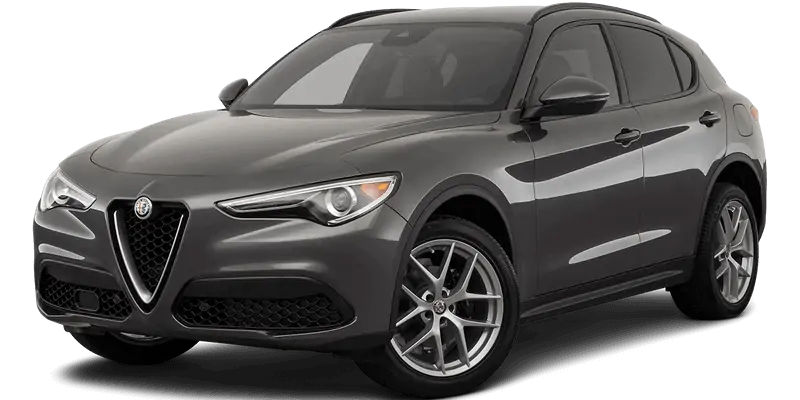
Chrysler (FCA US LLC) is recalling certain 2018-2019 Alfa Romeo
 Stelvio Quadrifoglio vehicles. The engine cooling hose may have inadequate webbing material allowing a coolant leak.
Remedy
Chrysler will notify owners, and dealers will replace the coolant hose, free of charge. The recall is expected to begin November 3, 2018. Owners may contact Chrysler
 customer service at 1-800-853-1403. Chrysler
 ’s number for this recall is U99.
Notes
Owners may also contact the National Highway Traffic Safety Administration Vehicle Safety Hotline at 1-888-327-4236 (TTY 1-800-424-9153), or go to www.safercar.gov.
Check if your Vehicle has a Recall
October 2018
Dealer Service Instructions for:
Safety Recall U99 / NHTSA 18V-635 Coolant Hose
Remedy Available
| 2018 – 2019 | (GU) | Alfa Romeo Stelvio Quadrifoglio Stelvio Quadrifoglio |
NOTE: This recall applies only to the above vehicles built from November 28, 2017 through August 30, 2018 (MDH 112800 through 083000).
| IMPORTANT: Some of the involved vehicles may be in dealer new vehicle inventory. Federal law requires you to complete this recall service on these vehicles before retail delivery. Dealers should also consider this requirement to apply to used vehicle inventory and should perform this recall on vehicles in for service. Involved vehicles can be determined by using the VIP inquiry process. |
Subject
The engine cooling hose on about 660 of the above vehicles may have been manufactured with an inadequate inner webbing material, which may allow coolant to leak. Engine cooling hose leakage may result in a loss of coolant causing the engine to overheat. An overheated engine may result in a loss of motive power. Loss of motive power can cause vehicle crash without prior warning.
Repair
Replace the engine coolant hose between the engine crankcase to automatic transmission oil heat exchanger on the right side of the engine.
Parts Information
| Description | Part Number |
|---|---|
| Engine Coolant Hose Kit | 68454280AA |
| Each package contains the following components: | |
| Description | Quantity |
| Hose | 1 |
| Clamps | 2 |
Dealers were provided an initial allocation of Engine Coolant Hose Kit Packages to service those vehicles assigned in the recall. Additional packages to service vehicles assigned in this recall must be order in DealerConnect thru Vin Specific Ordering.
Parts Return
No parts return required for this campaign.
Special Tools
The following special tools are required to perform this repair:
| wiTECH micro pod II |
| Laptop Computer |
| wiTECH Software |
Service Procedure
Hose Removal
- Position the vehicle on a suitable lift.
- Open the hood. Install a battery charger
 and verify that the charging rate provides 13.0 to 13.5 volts. Do not allow the charger to time out during the flash process. Set the battery charger timer (if so equipped) to continuous charge.
NOTE: Using wiTECH, perform a Scan Report and save a copy for any further investigations.
- Connect the wiTECH micro pod II to the vehicle data link connector.
- Place the ignition in the “RUN” position.
- Open the wiTECH 2.0 website.
- Enter your “User id” and “Password” and your “Dealer Code”, then select “Sign In” at the bottom of the screen. Click “Accept”.
- From the “Vehicle Selection” screen, select the vehicle to be updated.
- Create and save a Vehicle Scan Report (VSR) as follows:
a. From the left column in the analysis section, select “Reports”.
b. On the reports page, select “Scan Report”.
c. Select “ECU Summary” from the dropdown menu on the right.
d. Select “Printer Friendly” then save file type as “PDF”. Name the file with the last eight digits of the vehicle VIN.
- From the “Action Items” screen, select the “Topology” tab.
- From the “Topology” screen, select the “All DTCs” tab to view and clear any DTCs.
- Raise all electrical windows to the upper stop position.
NOTE: Make sure ALL the windows are closed fully. Disconnecting the battery when the windows are in a position other than the upper end stop will entail the need to run the window end stop learning procedure.
- Place the ignition in the “OFF” position and then remove the wiTECH micro pod II device and battery charger from the vehicle.
- Open the liftgate and support it so it will not close.
- Place the ignition in the “OFF” position and the vehicle must remain powered down for at least one minute before disconnecting the battery.
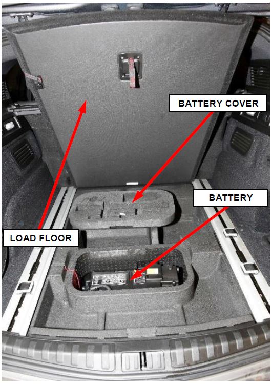
- Lift and support the rear compartment load floor, then remove the battery cover (Figure 1).
Figure 1 – Battery Location
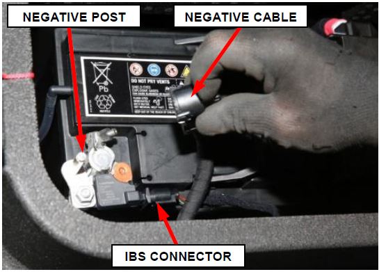
- Press the release button and disconnect the negative battery cable from the post. If equipped with an Intelligent Battery Sensor (IBS), disconnect the IBS connector (Figure 2).
Figure 2 – Battery Negative Terminal
- Raise and support the vehicle.
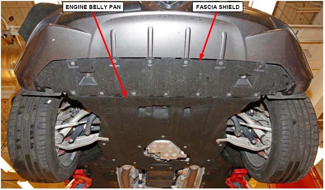
- Remove the engine belly pan Then remove the engine belly pan (Figure 3).
- Remove the fascia shield fasteners. Then remove the fascia shield (Figure 3).
Figure 3 – Engine Belly Pan and Fascia Shield
- Remove the right front tire and wheel assembly.
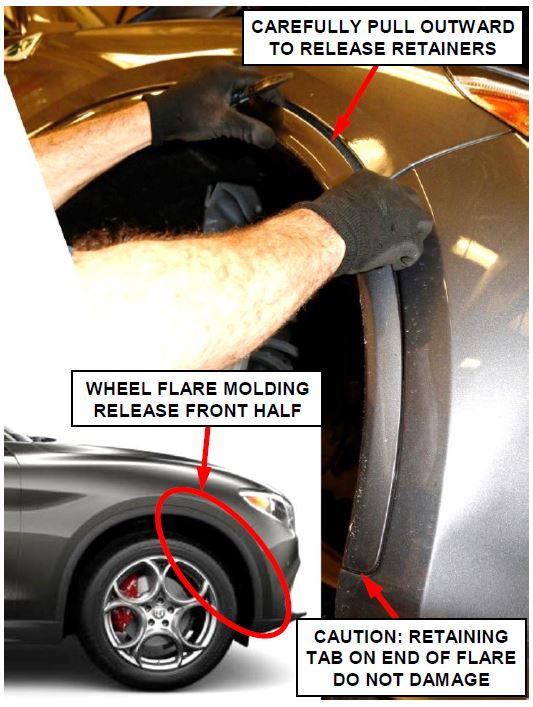
- Release the front half of the right front wheel flare molding from the wheel arch by carefully pulling outward to release the internal retainers (Figure 4).
NOTE: Only the front half of the right front wheel flare molding must be released in order to access two attachment screws securing the front wheelhouse panel to the front fascia.
Figure 4 – Right Front Wheel Flare
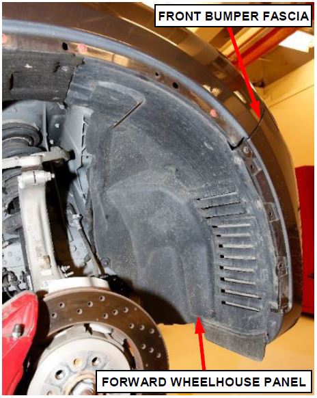
- In the right front wheelhouse, remove the forward wheelhouse panel fasteners. Then remove the forward wheelhouse panel (Figure 5).
Figure 5 – Right Front Wheelhouse
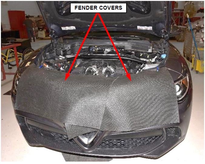
- Protect the painted surfaces of the vehicle around the engine compartment in order to prevent any damage to the vehicle paint (Figure 6).
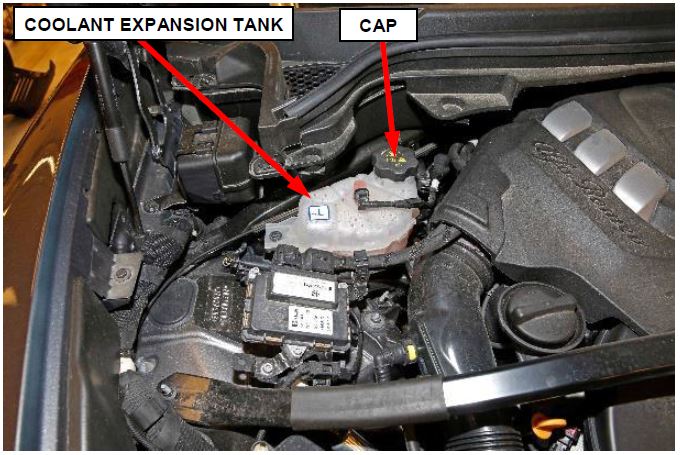
- With the engine cold, loosen the pressure cap on the engine coolant expansion tank (Figure 7).
Figure 6 – Protect Painted Surfaces
WARNING: Do not remove the cooling system expansion tank pressure cap with the system hot and under pressure because serious burns from coolant can occur.
- Prepare a suitable clean container to collect the coolant. Two containers are recommended because there are two drain cocks. Or open only one drain cock at a time in order to use the same container.
Figure 7 – Coolant Expansion Tank
NOTE: Do not waste reusable coolant. If the solution is clean, drain the coolant into a clean container for reuse.
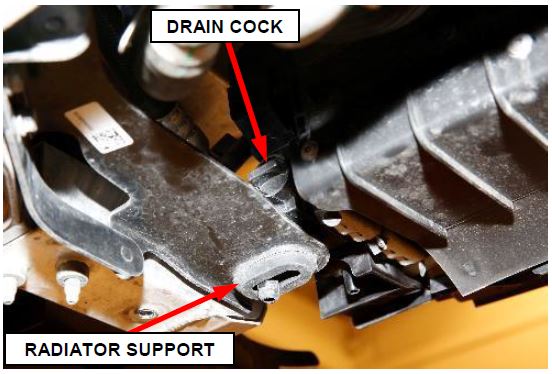
- Open the drain cock located on the left side tank of the high temperature primary radiator (Figure 8). Allow the coolant to drain into a suitable clean container for reuse.
Figure 8 – High Temperature Primary Radiator Drain Cock
NOTE: The high temperature primary radiator is located rearward of the condenser and low temperature primary radiator.
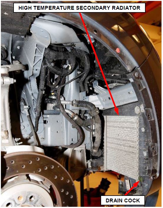
- Open the drain cock located on the right side tank of the high temperature secondary radiator (Figure 9). Allow the coolant to drain into a suitable clean container for reuse
NOTE: The high temperature secondary radiator is on the right side of the vehicle in front of the right front wheel.
Figure 9 – High Temperature Secondary Radiator Drain Cock
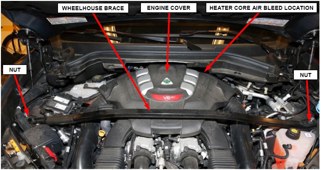
- Remove the engine compartment wheelhouse brace nuts then remove the wheelhouse brace (Figure 10).
- Lift up on the engine cover to release it from the retaining pins, then remove the engine cover (Figure 10).
Figure 10 – Wheelhouse Brace and Engine Cover
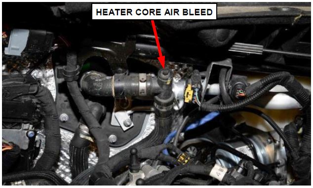
- Loosen the heater core air bleed to assist with coolant draining (Figure 11).
NOTE: The heater core air bleed is located near the cowl behind the left side of the air cleaner housing.
Figure 11 – Heater Core Air Bleed
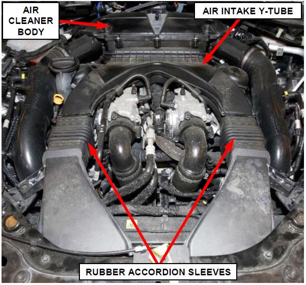
- Disengage the retaining pins securing the air intake Y-tube then remove the air intake Y-tube from the air cleaner box and release it from the air intake rubber accordion sleeves (Figure 12).
Figure 12 – Air Intake Y-Tube
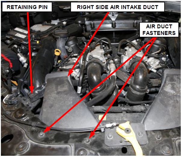
- Remove the two fasteners securing the right side air intake duct to the front support crossmember (Figure 13).
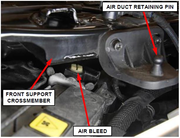
- Disengage the retaining pin securing the right side air duct to the front support crossmember then remove the right side air intake duct (Figure 13).
NOTE: Removal of the right side air duct will allow improved access to the high temperature primary radiator air bleed located below the front support crossmember on the top of the radiator right side tank.
Figure 13 – Right Side Air Duct
NOTE: The high temperature primary radiator air bleed is higher and rearward of the low temperature primary radiator air bleed. Do not open the low temperature primary radiator air bleed or air may enter the low temperature coolant system requiring bleeding of the low temperature System.
Figure 14 – High Temperature Primary Radiator Air Bleed
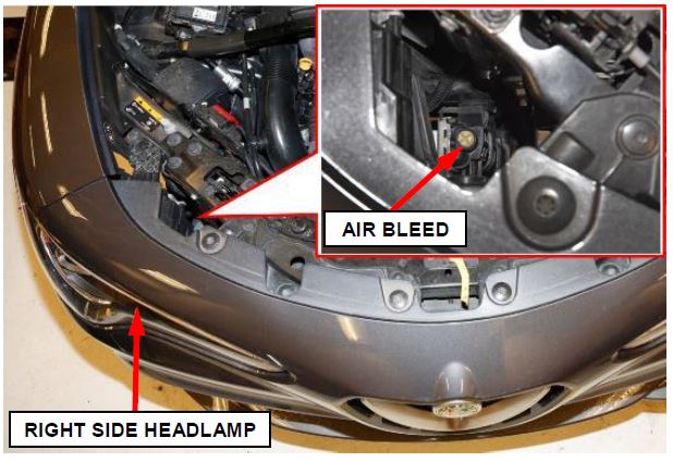
- Loosen the high temperature secondary radiator air bleed to assist with coolant draining (Figure 15).
NOTE: The high temperature secondary radiator air bleed is located behind and below the right side headlamp. Do not open the low temperature secondary radiator air bleed on the left side of the vehicle or air may enter the low temperature coolant system requiring bleeding of the low temperature system.
Figure 15 – High Temperature Secondary Radiator Air Bleed
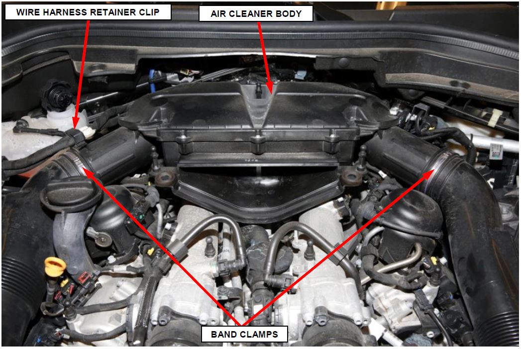
- Open the air cleaner body retaining clip and release the engine wiring harness (Figure 16).
- Release the right and left band clamps then disconnect the right and left air inlet tubes from the air cleaner body (Figure 16).
- Disengage the retaining pins securing the air cleaner body then remove the air cleaner body (Figure 16).
Figure 16 – Air Cleaner Body
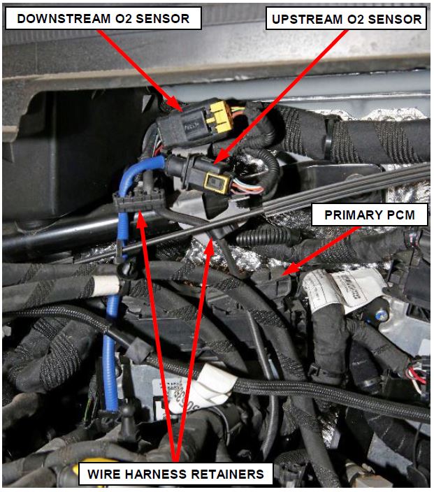
- Disconnect the electrical connections for the right side upstream and downstream Oxygen (O2) sensors (Figure 17).
- Release the O2 sensor wire harnesses from the retainers then positon the O2 sensor wire harnesses out of the way of the primary Powertrain Control Module (PCM) (Figure 17).
Figure 17 – Oxygen (O2) Sensors
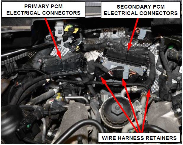
- Release the wiring from the retaining clips and cable tie on the secondary PCM bracket then position the wiring aside to access the PCM electrical connections (Figure 18).
- Disconnect the electrical connectors from the secondary PCM (Figure 18).
- Disconnect the electrical connectors from the primary PCM (Figure 18).
Figure 18 – PCM Electrical Connections
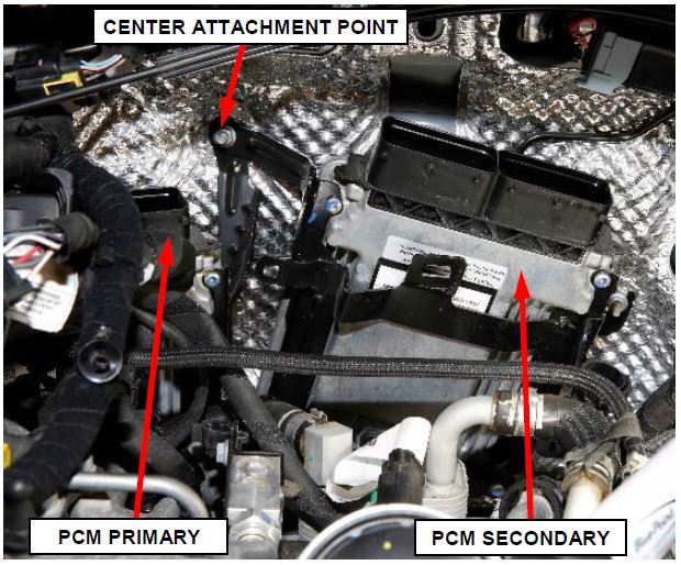
- Remove the nut from the PCM bracket center upper attachment point to the cowl (Figure 19).
Figure 19 – PCM Bracket Center Attachment
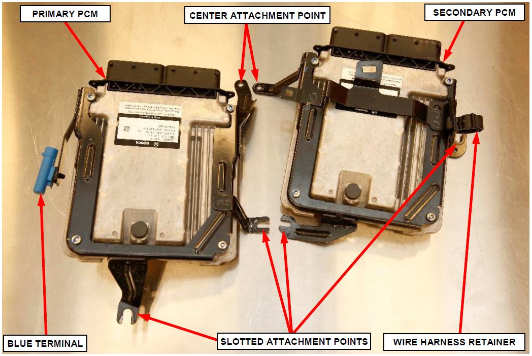
NOTE: The PCM bracket center upper attachment point is the only nut that must be fully removed. All other PCM bracket attachment points are slotted so the nuts only need to be loosened, not fully removed from the attachment point studs (Figure 20).
Figure 20 – PCM Brackets Attachment Points
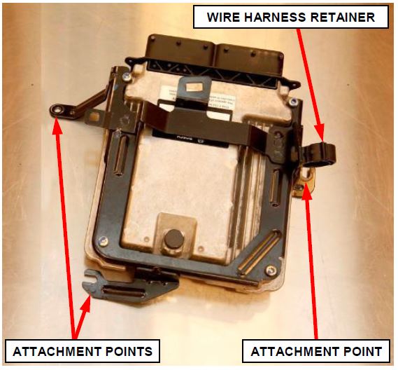
- Loosen the two remaining attachment nuts securing the secondary PCM bracket to the cowl (Figure 21).
- Remove the secondary PCM from the vehicle (Figure 21).
Figure 21 – Secondary PCM
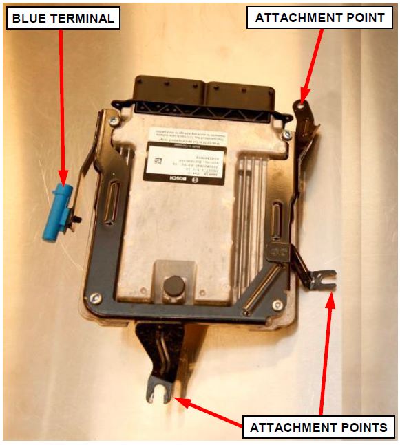
- Loosen the one remaining lower attachment nut securing the primary PCM bracket to the cowl (Figure 22).
NOTE: The primary PCM bracket lower attachment nut access is difficult but can be reached from inside the engine compartment. It is not necessary to access this nut from under the vehicle or to remove any additional components in order to access this nut. A long socket wrench extension with swivel adapter may be helpful.
- Disconnect the electrical connector from the blue terminal on the primary PCM bracket, then remove the primary PCM from the vehicle (Figure 22).
Figure 22 – Primary PCM
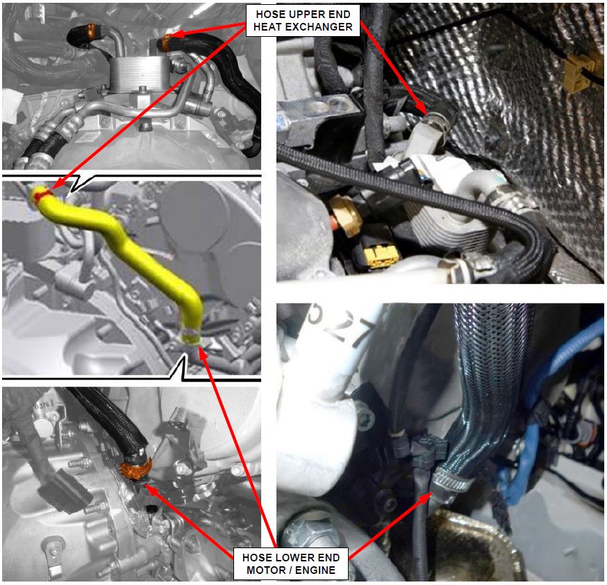
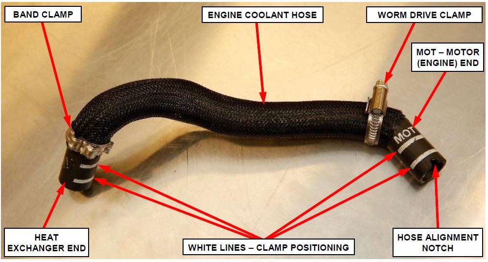
- Remove and discard the clamps from both ends of the engine coolant hose between the engine water supply pipe to automatic transmission oil heat exchanger on the right side of the engine (Figure 23).
- Remove and discard the engine coolant hose (Figure 23).
Figure 23 – Engine Coolant Hose
Hose Installation
- Install the new hose clamps onto the new hose (Figure 24).
NOTE: The worm drive clamp should be positioned at the lower (engine) end of the hose identified by the white letters “MOT” indicating motor printed on the hose. The band clamp should be positioned at the upper (heat exchanger) end of the hose (Figure 24).
- Install the new hose with clamps to the engine water supply pipe and the heat exchanger (Figure 23).
IMPORTANT: When installing the new hose, ensure the notches on each end of the hose index with the alignment feature on the water supply pipe and heat exchanger in order to prevent distorting the hose (Figure 24).
- Secure the hose clamps.
IMPORTANT: The hose clamps must be positioned between the white lines printed on the hose ends (Figure 24).
Figure 24 – Engine Coolant Hose
- Connect the electrical connector to the blue terminal on the primary PCM bracket, then install the primary PCM to the vehicle (Figure 22).
- Tighten the lower attachment nut securing the primary PCM bracket to the cowl 9 N·m (80 in. lbs.) (Figure 22).
- Install the secondary PCM to the vehicle (Figure 21).
- Install the nut to the PCM bracket center upper attachment point on the cowl (Figure 19).
- Tighten all attachment nuts securing the PCM brackets to the cowl 9 N·m (80 in. lbs.) (Figure 20).
- Connect the electrical connections to the primary PCM (Figure 18).
- Connect the electrical connections to the secondary PCM (Figure 18).
- Install the wiring to the retaining clips and secure the cable tie on the secondary PCM bracket (Figure 18).
- Connect the electrical connections for the right side upstream and downstream Oxygen (O2) sensors then secure the O2 sensor wire harnesses to the retainers (Figure 17).
- Install the air cleaner body to the engine then engage the retaining pins securing the air cleaner body to the engine (Figure 16).
- Connect the right and left air inlet tubes to the air cleaner body then secure the right and left band clamps (Figure 16).
- Install the engine wiring harness to the air cleaner body retaining clip then secure the clip (Figure 16).
- Close the drain cock located on the right side tank of the high temperature secondary radiator (Figure 9).
- Close the drain cock located on the left side tank of the high temperature primary radiator (Figure 8).
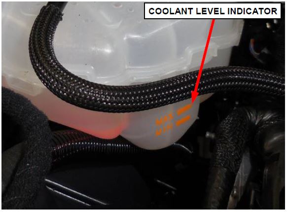
- Fill the cooling system coolant expansion tank with the captured coolant until coolant is coming out of the three bleed screws and tighten the bleed screws (Figures 11, 14, 15). Add additional coolant as necessary to bring the coolant reservoir to the proper lever.
- Install and tighten the coolant reservoir cap (Figure 7).
- Install the right side air duct to the front support crossmember while engaging the retaining pin (Figure 13).
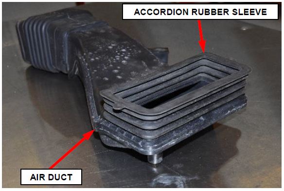
IMPORTANT: Ensure the accordion rubber sleeve which seals the right side air duct to the radiator shroud is properly positioned not distorted or folded over before installing the right side air duct fasteners (Figure 25).
Figure 25 – Right Side Air Duct
- Install and tighten the fasteners securing the right side air intake duct to the front support crossmember (Figure 13).
- Install the air intake Y-tube to the air cleaner body and the air intake rubber accordion sleeves. Engage the retaining pins to secure the air intake Y-tube to the engine (Figure 12).
- Connect the negative battery cable to the battery post. If equipped with an Intelligent Battery Sensor (IBS), connect the IBS connector (Figure 2).
NOTE: In the event that the liftgate is closed while the battery is disconnected:
a. Fold the rear left seat back down.
b. Remove the access cover on the inside liftgate.
c. Pull the cord to release the liftgate latch.
- Install the battery cover and lower the rear compartment load floor (Figure 1).
- The liftgate must be closed manually after connecting the battery. Once closed, the opening/closing electrical control function is acquired.
- Start the engine and let it idle for about two minutes.
- Remove the air from the cooling system by pumping the accelerator regularly and gradually (every 30 seconds) up to a speed of around 2500 rpm. This operation must be carried out so that the thermostat opens and the fan switches on and off at least 3 times. During this operation, keep the climate control system switched off to prevent the fan coming on not due to the heating of the coolant.
- Place the ignition in the “OFF” position.
- Inspect for any coolant leaks.
- Install the engine cover and secure it to the retaining pins (Figure 10).
- Install the engine compartment wheelhouse brace, then install and tighten the fasteners to 25 N·m (15 ft. lbs.) (Figure 10).
- Install the right front forward wheelhouse panel and secure the fasteners (Figure 5).
- Secure the right front wheel flare molding to the wheel arch (Figure 4).
- Install the right front tire and wheel assembly. Tighten the wheel mounting bolts to 120 N·m (89 ft. lbs.).
- Install the fascia shield and secure the fasteners (Figure 3).
- Install the engine belly pan and secure the fasteners (Figure 3).
- Lower the vehicle.
- Initializing the steering is required. This will be indicated by a warning light on the Instrument Panel Cluster (IPC) illuminating. Start the engine, turn the steering wheel from one lock to the other and turn it back into the center position.
- If equipped with an electric tow hook, press and hold the button on the rear trim panel for at least 10 seconds. The LED light will turn on continuously to confirm the initialization has taken place.
- Road test the vehicle to verify the cooling system is purged of air.
- Allow the engine to cool then check for proper coolant level in the coolant expansion tank (Figure 26).
- Close the hood.
Figure 26 – Coolant Expansion Tank
Completion Reporting and Reimbursement
Claims for vehicles that have been serviced must be submitted on the DealerCONNECT Claim Entry Screen located on the Service tab. Claims paid will be used by FCA to record recall service completions and provide dealer payments.
Use the following labor operation number and time allowance:
| Labor Operation Number | Time Allowance | |
|---|---|---|
| Replace Coolant Hose | 07-U9-91-82 | 2.9 hours |
| Floor Plan Reimbursement | 95-95-95-97 | Calculate See Below |
Floor Plan Reimbursement represents the vehicle’s average daily allowance (see table below) multiplied by the number of days the vehicle was in dealer inventory and not available for sale. This reimbursement is limited to the number of days from the date of the stop sale to the date that the remedy was made available. Note: If the vehicle was received by your dealership (KZX date) AFTER the stop sale date, you will use the KZX date instead of the stop sale date. For this Recall, the stop sale was initiated on 09/21/2018 and the remedy was made available on 10/02/2018, therefore, the number of days cannot exceed 11 days.
| Vehicle | Average Daily Allowance |
|---|---|
2018 (GU) Alfa Romeo Stelvio Quadrifoglio Stelvio Quadrifoglio | $6.47 |
2019 (GU) Alfa Romeo Stelvio Quadrifoglio Stelvio Quadrifoglio | $6.47 |
Add the cost of the recall parts package plus applicable dealer allowance to your claim.
NOTE: See the Warranty Administration Manual, Recall Claim Processing Section, for complete recall claim processing instructions.
Dealer Notification
To view this notification on DealerCONNECT, select “Global Recall System” on the Service tab, then click on the description of this notification.
Owner Notification and Service Scheduling
All involved vehicle owners known to FCA are being notified of the service requirement by first class mail. They are requested to schedule appointments for this service with their dealers. A generic copy of the owner letter is attached.
Vehicle Lists, Global Recall System, VIP and Dealer Follow Up
All involved vehicles have been entered into the DealerCONNECT Global Recall System (GRS) and Vehicle Information Plus (VIP) for dealer inquiry as needed.
GRS provides involved dealers with an updated VIN list of their incomplete vehicles. The owner’s name, address and phone number are listed if known. Completed vehicles are removed from GRS within several days of repair claim submission.
To use this system, click on the “Service” tab and then click on “Global Recall System.” Your dealer’s VIN list for each recall displayed can be sorted by: those vehicles that were unsold at recall launch, those with a phone number, city, zip code, or VIN sequence.
Dealers must perform this repair on all unsold vehicles before retail delivery. Dealers should also use the VIN list to follow up with all owners to schedule appointments for this repair.
Recall VIN lists may contain confidential, restricted owner name and address information that was obtained from the Department of Motor Vehicles of various states. Use of this information is permitted for this recall only and is strictly prohibited from all other use.
Additional Information
If you have any questions or need assistance in completing this action, please contact your Service and Parts District Manager.
Customer Services / Field Operations
FCA US LLC
This notice applies to your vehicle,
[Model Year and Model] VIN XXXXXXXXXXXXXXXXX U99/NHTSA 18V-635
LOGO
VEHICLE PICTURE
YOUR SCHEDULING OPTIONS
- RECOMMENDED OPTION Call your authorized Chrysler
 / Dodge
 / Jeep
 ® / RAM
 / Alfa Romeo
 Dealership
 - Call the FCA Recall Assistance Center at 1-800-853-1403 or Alfa Romeo Premium Care at 1-844253-2872. An agent can help schedule an appointment
- Visit mopar.com, scan the QR code below, or download the Mopar Owner’s Companion App.
QR Code
Get access to recall notifications, locate your nearest dealer, and more through this website or Mopar Owner’s Companion App. You will be asked to provide your Vehicle Identification Number (VIN) to protect and verify your identity. The last eight characters of your VIN are provided above.
DEALERSHIP INSTRUCTIONS
Please reference Safety Recall U99.
IMPORTANT SAFETY RECALL
Dear [Name],
This notice is sent to you in accordance with the National Traffic and Motor Vehicle Safety Act.
FCA has decided that a defect, which relates to motor vehicle safety, exists in certain [2018 and 2019 Model Year (GU) Alfa Romeo Stelvio Quadrifoglio] vehicles.
It is extremely important to take steps now to repair your vehicle to ensure the safety of you and your passengers.
WHY DOES MY VEHICLE NEED REPAIRS?
The engine cooling hose on your vehicle [1] may have been manufactured with an inadequate inner webbing material, which may allow coolant to leak. Engine cooling hose leakage may result in a loss of coolant causing the engine to overheat. An overheated engine may result in a loss of motive power. Loss of motive power can cause vehicle crash without prior warning.
HOW DO I RESOLVE THIS IMPORTANT SAFETY ISSUE?
FCA will repair your vehicle [2] free of charge (parts and labor). To do this, your dealer will replace the engine coolant hose. In addition, your dealer will require your vehicle for proper check-in, preparation, and check-out during your visit. Your time is important to us; please be aware that these steps may require more time. The estimated repair time is three hours. We recommend that you schedule a service appointment to minimize your inconvenience. Please bring this letter with you to your dealership.
TO SCHEDULE YOUR FREE REPAIR,
CALL YOUR ALFA ROMEO DEALER TODAY
WHAT IF I ALREADY PAID TO HAVE THIS REPAIR COMPLETED?
If you have already experienced this specific condition and have paid to have it repaired, you may visit www.fcarecallreimbursement.com to submit your reimbursement request online. [3] Once we receive and verify the required documents, reimbursement will be sent to you within 60 days. If you have had previous repairs performed and/or already received reimbursement, you may still need to have the recall repair performed.
We apologize for any inconvenience, but are sincerely concerned about your safety. Thank you for your attention to this important matter.
Customer Assistance/Field Operations
FCA US LLC
Mr. Mrs. Customer
1234 Main Street
Hometown, MI 48371
[1] If you no longer own this vehicle, please help us update our records. Call the FCA Recall Assistance Center at 1-800-853-1403 to update your information.
[2] If your dealer fails or is unable to remedy this defect without charge and within a reasonable time, you may submit a written complaint to the Administrator, National Highway Traffic Safety Administration, 1200 New Jersey Ave., S.E., Washington, DC 20590, or you can call the toll-free Vehicle Safety Hotline at 1-888-327-4236 (TTY 1-800-4249153), or go to safercar.gov.
[3] You can also mail in your original receipts and proof of payment to the following address for reimbursement consideration: FCA Customer Assistance, P.O. Box 21-8004, Auburn Hills, MI 48321-8007, Attention: Recall Reimbursement.
Note to lessors receiving this recall notice: Federal regulation requires that you forward this recall notice to the lessee within 10 days.
U99
October 2018
 Loading...
Safety Recall Advanced Communication – U99
09/21/2018
 Loading...
Recall Acknowledgement
October 5, 2018
 Loading...
- Item Name: MOPAR Antifreeze/Coolant 50/50 Prediluted MS.90032
- Part Number: 68163849AB
- Brand: MOPAR
- Application: 2017-2020 ALFA ROMEO
 GIULIA, 2018-2020 ALFA ROMEO
 STELVIO, 2017-2019 CHRYSLER
 PACIFICA, 2016 (CHRYSLER
 TOWN & COUNTRY), (DODGE DART), 2016-2017 (CHRYSLER
 200), (DODGE VIPER), (JEEP
 PATRIOT), 2016-2019 (CHRYSLER
 300), (DODGE JOURNEY), (RAM
 1500, 2500, 4500, 5500)
 - 2015-2019 DODGE CHALLENGER, 2016-2020 (DODGE CHARGER, GRAND CARAVAN), (JEEP
 COMPASS), 2016-2021 (DODGE DURANGO), (RAM
 PROMASTER 1500, 2500, 3500), 2013, 2016-2018 FIAT
 500, 2016-2019, 2021 JEEP
 CHEROKEE/GRAND CHEROKEE, 2015-2021 JEEP
 WRANGLER, 2015-2020 RAM
 3500
3500
- Genuine MoparYear/ 150,000 Mile Coolant
- 1 Gallon Concentrate Bottle
- Contains a bittering agent
- Safe for all radiators and all gas/diesel engines
- PREDILUTED ANTIFREEZE AND COOLANT: Engineered to support any vehicle's engine cooling system to enhance performance and provide protection. This item contains a bittering agent called Denatonium Benzoate.
- PROPRIETARY BLEND: Contains 10X the scale-fighting inhibitors to ensure maximum cooling performance while protecting against scale, corrosion, and other damage
- SUPERIOR CHEMISTRY: Free from 2-EHA, silicate, nitrite, borate, and amines to keep your vehicle functioning in prime condition
- UNIVERSAL FORMULA: Compatible with any color or type of existing antifreeze and coolant in your car's system
- LONG-LASTING: Offers 2X the average warranty coverage, cooling your engine system for over 10 years or 300,000 miles of service
- Package Weight: 4.227 kg
- Product Type: Auto Part
- Package Quantity: 1
- No Batteries Required
- Embittered - Contains Bittering Agent
- UNSURPASSED FREEZE PROTECTION AND ANTI-BOIL PERFORMANCE outperforms industry standards
- HYBRID ORGANIC ACID TECHNOLOGY FIGHTS RUST, SCALE & CORROSION while protecting all cooling system metals (including aluminum)
- HIGH-QUALITY ADDITIVES PROTECT AGAINST LEAKS and won’t harm gaskets, hoses, plastics or original vehicle finish
- PRE-MIXED YELLOW FORMULA IS READY-TO-USE in a 50/50 ratio with deionized water to protect all modern engine components from winter freezing (-34F) and summer boiling (265F).
- 5 YEAR/150,000 MILE GUARANTEE protects against engine failure caused by freeze-ups or boil-overs
- 1 GALLON ENGINE ANTIFREEZE/COOLANT: Fully compatible with other extended life antifreeze/coolants. This item contains a bittering agent called Denatonium Benzoate.
- PROTECTS: Advanced formulation prevents rust & corrosion protecting all engine cooling system components
- DESIGNED FOR NORTH AMERICAN VEHICLES: Recommended for use with Ford, Chrysler, and GM vehicles that require an orange organic acid technology formula
- GUARANTEED: When installed as part of a complete flush and fill, PEAK guarantees this coolant will provide service life protection of up to 150,000 miles or 5 years.
- CONCENTRATED FORMULA: Ideal for flushing, filling, or topping off your cooling system
- Unsurpassed freeze protection and anti-boil performance outperforms industry standards
- Organic acid technology resists rust, scale & corrosion while protecting all cooling system metals (including aluminum)
- High-quality additives protect against leaks and won’t harm gaskets, hoses, plastics or original vehicle finish
- Orange concentrate formula should be mixed with clean tap water or demineralized water at 50/50 ratio for temperatures -34 to 265F; 60/40 for -62 to 270F; and 70/30 for -84 to 267F
- 5 year/150,000 mile guarantee protects against engine failure caused by freeze-ups or boil-overs
- 5-Year/100000 Mile
- Genuine OEM Dodge/Mopar factory fit part
- Package Dimensions: 16.8 " L x 15.9 " W x 5.4 " H
- Fit type: Vehicle Specific
- 1 GALLON ENGINE ANTIFREEZE/COOLANT: Fully compatible with other extended life antifreeze/coolants. This item contains a bittering agent called Denatonium Benzoate.
- PROTECTS: Advanced formulation prevents rust & corrosion protecting all cooling system components. This product contains a bittering agent.
- DESIGNED FOR NORTH AMERICAN VEHICLES: Recommended for use with Alfa Romeo, Chrysler, Dodge, Fiat
 , Jeep
 and Rams that require a purple formula
 - GUARANTEED: When installed as part of a complete flush and fill, PEAK guarantees this coolant will provide service life protection of up to 350,000 miles or 5 years.
- 50/50 PREDILUTED FOR QUICK TOP OFFS: Already prediluted to make topping off your cooling system a breeze
- Contains Alugard Plus for compatibility with all ethylene glycol-based coolants in automobiles and light duty trucks
- Fights corrosion, scaling and rust while protecting all cooling system metals (including aluminum)
- High-quality additives protect against leaks and won’t harm gaskets, hoses, plastics or original vehicle finish
- Pre-mixed yellow formula is ready-to-use in a 50/50 ratio with deionized water to protect all modern engine components from winter freezing (-34F) and summer boiling (265F).
- Contains 30 – 50 ppm of denatonium benzoate as a bittering agent
Last update on 2025-05-08 / Affiliate links / Images from Amazon Product Advertising API
This product presentation was made with AAWP plugin.
