| “This site contains affiliate links for which OEMDTC may be compensated” |
January 25, 2019 NHTSA CAMPAIGN NUMBER: 19V021000
A drag link separation can cause a loss of steering control, increasing the risk of crash.
NHTSA Campaign Number: 19V021
Manufacturer Chrysler (FCA US LLC)
Components STEERING
Potential Number of Units Affected 795,575
Summary
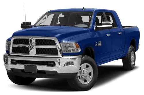
Chrysler (FCA US LLC) is recalling certain 2013-2018 Ram
 3500 and 2014-2018 Ram
 3500 Chassis Cab and Ram
 2500 vehicles. The outboard steering linkage jam nut may loosen, allowing one end of the drag link to separate.
Remedy
Chrysler will notify owners, and dealers will check the steering linkage jam nut tightness, replacing the drag link assembly or welding the nut to the adjuster sleeve, free of charge. The recall began March 22, 2019. Owners may contact Chrysler
 customer service at 1-800-853-1403. Chrysler
 ’s number for this recall is V06.
Notes
Owners may also contact the National Highway Traffic Safety Administration Vehicle Safety Hotline at 1-888-327-4236 (TTY 1-800-424-9153), or go to www.safercar.gov.
Check if your Vehicle has a Recall
Revised (2) April 2019
Dealer Service Instructions for:
Safety Recall V06 / NHTSA 19V-021 Drag Link
NOTE: Added 2013 MY D2 vehicles to Remedy Available section.
NOTE: Only 2013, 2017 and 2018 MY vehicle remedies are available at this time. Part requests for 2014 through 2016 MY vehicles will be rejected until further notice.
SPECIAL NOTE: For 2014-2016 MY vehicles towed in and/or separation has occurred, a STAR Case must be submitted, then contact the STAR Center to request parts.
Remedy Available
| 2017-2018 | (DJ) | RAM 2500 Pickup 2500 Pickup |
| 2013, 2017-2018 | (D2) | RAM 3500 Pickup 3500 Pickup |
| 2017-2018 | (DD) | RAM 3500 Cab Chassis 3500 Cab Chassis |
| 2017-2018 | (DF) | RAM 3500 10K LB. Cab Chassis 3500 10K LB. Cab Chassis |
Remedy NOT Available
| 2014-2016 | (DJ) | RAM 2500 Pickup 2500 Pickup |
| 2014-2016 | (D2) | RAM 3500 Pickup 3500 Pickup |
| 2014-2016 | (DD) | RAM 3500 Cab Chassis 3500 Cab Chassis |
| 2016 | (DF) | RAM 3500 10K LB. Cab Chassis 3500 10K LB. Cab Chassis |
NOTE: Some VINs in vehicles above may have been identified as not involved in this recall and therefore have been excluded from this recall.
| IMPORTANT: Some of the involved vehicles may be in dealer new vehicle inventory. Federal law requires you to complete this recall service on these vehicles before retail delivery. Dealers should also consider this requirement to apply to used vehicle inventory and should perform this recall on vehicles in forservice. Involved vehicles can be determined by using the VIP inquiry process. |
Subject
The drag link on about 795,000 of the above vehicles may have been built with an outboard steering linkage jam nut that could loosen allowing one end of the drag link to separate from the adjuster sleeve. A drag link separation can result in a loss of directional steering control, which can cause a vehicle crash without prior warning.
Repair
Inspect the torque values. If the torque values meet requirement, the nuts will be welded to the adjuster sleeve. If the torque values do not meet requirement, the threads will be measured. If thread engagement is acceptable, the link will be reassembled, the vehicle will be aligned, and the nuts will be welded to the adjuster sleeve. If the thread engagement is not adequate, the drag link assembly will be replaced.
Alternate Transportation
Dealers should attempt to minimize customer inconvenience by placing the owner in a loaner vehicle if inspection determines that a drag link assembly is required and the vehicle must be held overnight.
Parts Information
No parts will be distributed initially.
If a replacement drag link is needed, after performing Sections A and B, please contact the STAR Center for additional directions. Part numbers listed below are for reference only.
Very few vehicles are expected to require drag link replacement.
| Description | Part Number |
|---|---|
| Assembly, Drag Link | CSZHV061AA |
| Hex Lock Nut, Tie Rod (2 required) | 06505623AA |
| Paint, Black (MS-PF-1-25)
(Each container of paint will repair approximately 25 vehicles) | 68317791AA |
NOTE: If any part of this procedure cannot be performed during disassembly or assembly, a STAR Case must be submitted.
NOTE: A STAR Case must be submitted, then contact the STAR Center to request parts. Please provide the VIN, Model Year, Mileage, PN, Dealer Code and measurements from Steps 4 and 5 in section B. If approved, STAR will place the order for the Drag Link part. The Drag Link part will be shipped from your facing PDC.
Once STAR has confirmed parts can be ordered, Dealers must place order for the Hex Lock Nut and black paint, as necessary. Hex Lock Nut will be shipped from your parts distribution center and the black paint will be shipped SSD.
Parts Return
Do not scrap the part, if the Drag Link Assembly is replaced, the Star Center will initiate the process for returning to the Quality Engineering Center for review.
All returned parts and associated claims will be reviewed and are subject to charge back.
Special Tools
The following special tools are required to perform this repair:
| Flux Cored Arc Weld (MIG) or equivalent
GMAW (MIG) welding machine (140-150 amps) |
| Puller, Tie Rod |
| Crowsfoot Wrench, 41mm (SCOM41) |
Service Procedure
A. Inspect Drag Link Assembly
- If no separation is observed, continue to Step 2.
- If the vehicle was towed in and separation has occurred, continue to section Replace Drag Link Assembly.
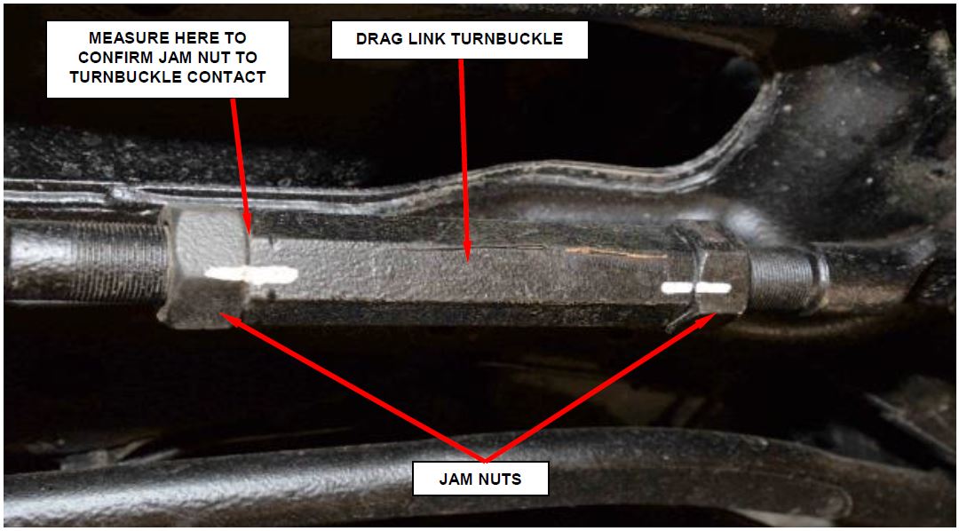
- Using a .020” feeler gauge, confirm jam nut contact to drag link turnbuckle. If no contact is noted, proceed to section Measure Drag Link Assembly Threads (Figure 1). Jam nut to turnbuckle gap is not considered separation.
- Using a paint pen or equivalent, mark both jam nuts and turnbuckle with lines (Figure 1).
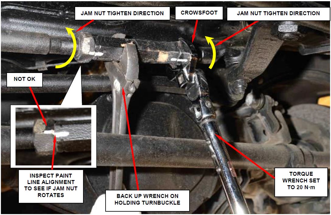
- Hold the drag link turnbuckle with back-up wrench (Figure 2).
- Using a 41 mm crowsfoot, such as Special Tool 2069400190 (Snap-on SCOM41) or equivalent, set a torque wrench to 20 N·m (15 ft. lbs.) (Figure 2).
Figure 1 – Mark Jam Nuts and Turnbuckle
NOTE: If using a digital torque wrench during the inspection, observe the torque wrench digital reading to determine if minimum torque of 20 N·m (15 ft. lbs.) is achieved.
NOTE: Some jam nut movement may occur when tightening from 20 N·m (15 ft. lbs.) to 148 N·m (109 ft. lbs.). DO NOT replace the drag link if initial 20 N·m (15 ft. lbs.) is achieved.
- Rotate each jam nut in direction as shown (tightening direction) until wrench clicks or 20 N·m (15 ft. lbs.) is achieved (Figure 2).
- If paint lines do not show nut rotation, continue to section Weld Turnbuckle Jam Nuts.
- If either paint line shows nut rotation, continue to section Measure Drag Link Assembly Threads.
Figure 2 – Inspect for Jam Nut Movement
B. Measure Drag Link Assembly Threads
- Back off both jam nuts enough to paint mark threads.
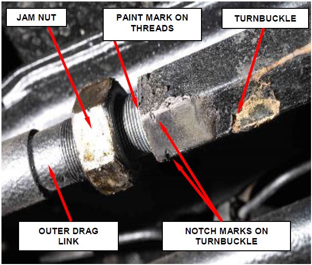
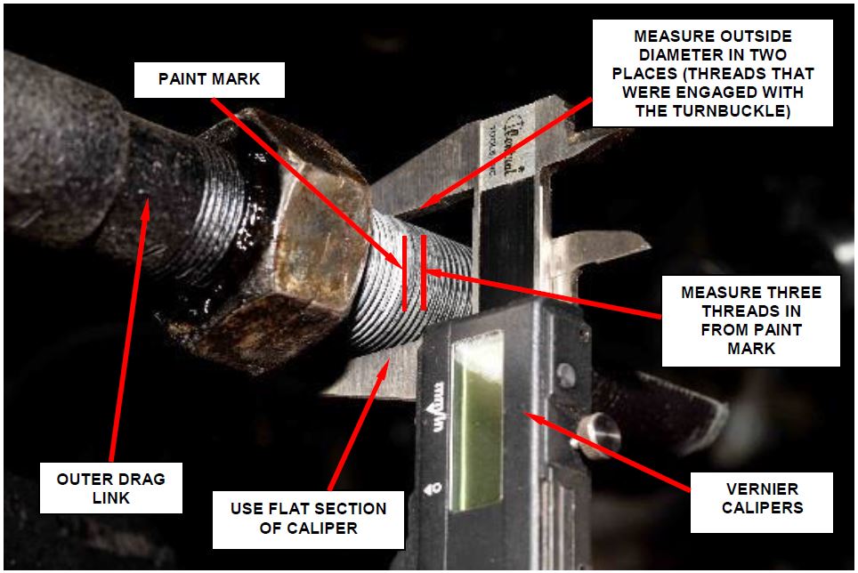
- Paint mark threads of outer drag link at turnbuckle (Figure 3).
Figure 3 – Paint Mark on Threads
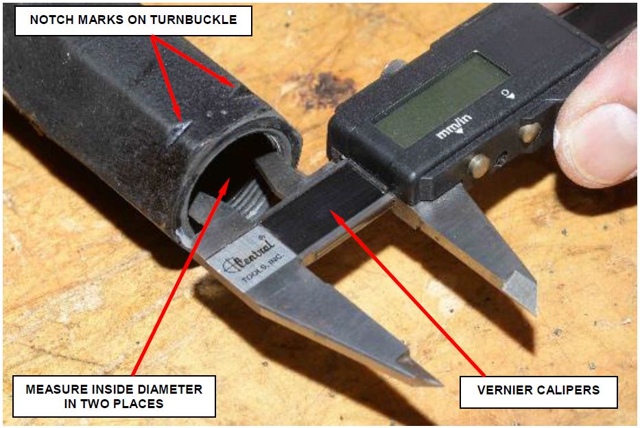
NOTE: Turnbuckle end with notch marks on hex goes toward the outer drag link.
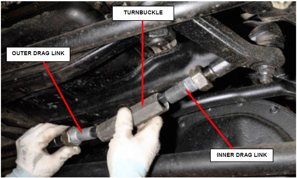
- Remove the turnbuckle from the inner and outer drag links (Figure 4).
Figure 4 – Remove Turnbuckle
- Using Vernier Calipers, measure and record the inside diameter of the turnbuckle (end with notch marks on hex) (Figure 5).
NOTE: Measure the inside diameter at two different locations (90° from each other). Use the largest measurement.
Figure 5 – Measure Inside Diameter of Turnbuckle at Notched End
- Using Vernier Calipers, measure and record the major outside diameter of the outer drag link threads 5mm (0.20 in. – approx 3 threads) from paint mark denoting end of turnbuckle (Figure 6). Be sure to measure using the flats on the calipers, do not measure inside the thread pitch (Figure 6).
NOTE: Measure the outside diameter at two different locations (90° from each other). Use the smallest measurement.
Record smallest outer thread diameter (Step 5):
Record largest inner thread diameter (Step 4):
Subtract (smallest outer – largest inner):
- If the result of the subtraction is 0.6 mm (0.024 in) or less, continue to section Replace Drag Link Assembly.
- If the result of the subtraction is greater than 0.6 mm (0.024 in), assemble the turnbuckle and continue to section Weld Turnbuckle Jam Nuts.
Figure 6 – Measure Outside Diameter of Outer Drag Link
C. Weld Turnbuckle Jam Nuts
NOTE: DO NOT WELD COLD, allow the parts to warm to room temperature, above 65° F (18° C).
NOTE: DO NOT LOOSEN JAM NUTS if steering wheel is centered and toe adjustment is not required.
- Adjust the toe if required and center the steering wheel.
- After adjustment, using a backer wrench and a 41 mm crowsfoot, such as Special Tool 2069400190 (Snap-on SCOM41) or equivalent, tighten the drag link turnbuckle jam nuts to 148 N·m (109 ft. lbs.). Make sure the toe setting does not change during tightening (Figure 2).
- Road test to verify the steering wheel is straight prior to welding.
- Disconnect the battery negative cable(s).
WARNING:
- When Welding or working with Adhesives always wear safety goggles and gloves to prevent contact with chemicals and to prevent weld spatter, sparks, and sharp metal from causing bodily injury.
- Wear an approved respirator while welding and during the application of adhesives to prevent inhalation of harmful vapors.
- Always remove NVH (Noise Vibration and Harshness) foam from welding repair area, as material is flammable.
WARNING: Failure to follow these instructions may result in possible serious or fatal injury.
Welding
- Comply with all federal, state and local regulations to avoid any injuries due to shock, fires, fumes, sparks and liquids.
- All flammable materials or liquid should be stored in tightly sealed and labeled containers, and used only in well ventilated areas.
- No spark producing equipment should be permitted in any area where flammable materials are being handled or stored.
- Clean the areas to be welded. Areas must be free of dirt, oil, water, salt, undercoating, moisture or any other contaminant that would affect the weld, then wire brush the area (Figure 7).
Figure 7 – Clean the Areas to be Welded
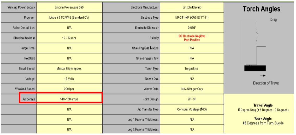
- Following the weld procedure values in chart below (Figure 8).
Figure 8 – Weld Procedure Values
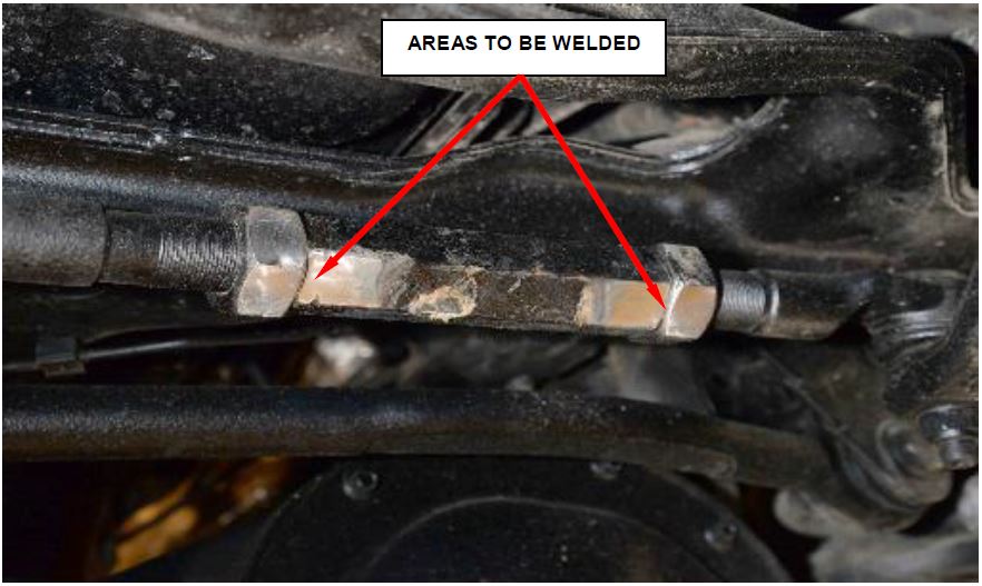
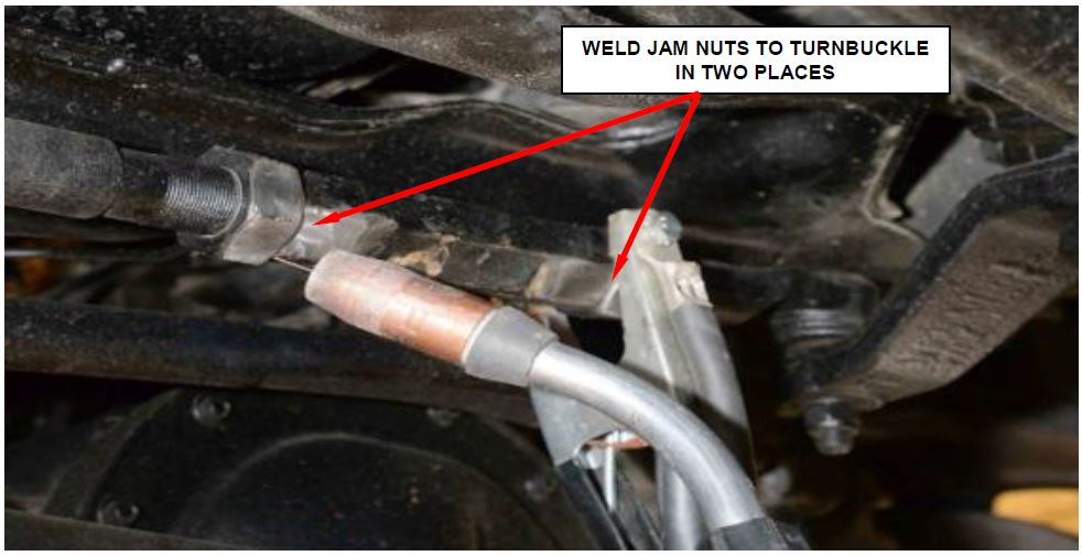
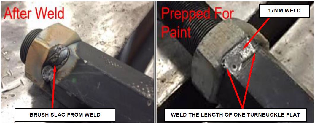
- Using a Lincoln Powerwave 350 Flux Cored Arc Weld (MIG) or equivalent GMAW (MIG) welding machine (140-150 amps), apply a 17mm long weld the length of one turnbuckle flat on each jam nut (Figure 9).
Figure 9 – Weld Both Jam Nuts to the Turnbuckle
- Wire brush the slag from the surface of the welds (Figure 10).
- Allow to cool to room temperature.
Figure 10 – Prepare areas for Paint
NOTE: Each jam nut must hold a breakaway torque of 105 N·m (77 ft. lbs.).
- Using a backer wrench and a 41 mm crowsfoot, such as Special Tool 2069400190 (Snap-on SCOM41) or equivalent, set a torque wrench to 105 N·m (77 ft. lbs.) and attempt to loosen each jam nut (ref: Figure 2 for set-up).
- If both jam nuts do not rotate (breakaway), continue to step 11.
- If either jam nut rotates (breakaway), repeat Steps 5 through 10 on a different turnbuckle flat.
- Paint the area to prevent rust using MS-PF-1-25 black paint or equivalent.
- Remove the supports and lower the vehicle.
- Connect the negative battery cable and return the vehicle to the customer.
D. Replace Drag Link Assembly
- Raise and support the vehicle.
- Remove the right front tire and wheel assembly.
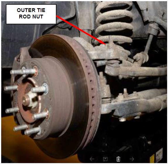
- Remove and DISCARD the outer drag link to tie rod nut (Figure 11).
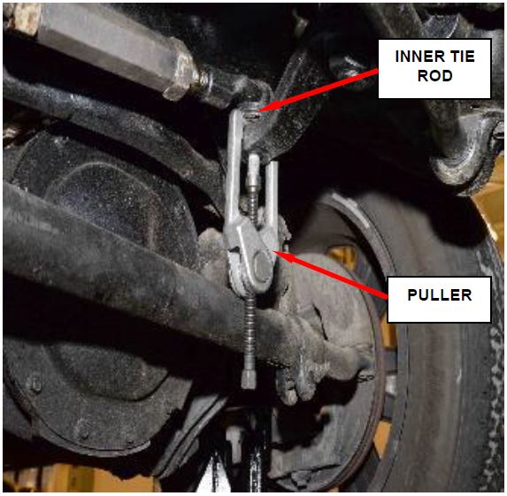
- Remove the outer drag link tie rod from the knuckle using C-3894-A (puller shown in Figure 12).
Figure 11 – Outer Tie Rod
- Remove and DISCARD the inner drag link to pitman arm nut (Figure 12).
- Remove the inner tie rod end from the pitman arm using special tool C-3894-A (Figure 12).
- Remove and RETURN the drag link assembly. See Parts Return section.
NOTE: Prior to installing tapered end suspension components, clean male and female surfaces with brake clean.
Figure 12 – Inner Tie Rod
- Position the NEW drag link assembly to the vehicle.
- Install the inner drag link tie rod end to pitman arm using a NEW nut and tighten to 37 N·m Plus 180° (27 ft. lbs. Plus 180°).
- Install outer drag link tie rod end to the knuckle and tighten the NEW nut to 60 N·m Plus 105° (44 ft. lbs. Plus 105°).
- Install the right front tire and wheel assembly and tighten to proper torque specification (Figure 13).
Figure 13 – Wheel Assembly Torque Specifications
- Remove the supports and lower the vehicle.
- Adjust the toe and center the steering wheel.
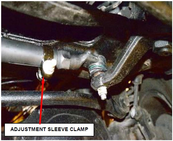
- After adjustment tighten tie rod adjustment sleeve clamp bolt to the 75 N·m (55 ft.) (Figure 14).
Figure 14 – Adjustment Sleeve Clamp
- Return the vehicle to the customer.
Completion Reporting and Reimbursement
Claims for vehicles that have been serviced must be submitted on the DealerCONNECT Claim Entry Screen located on the Service tab. Claims paid will be used by FCA to record recall service completions and provide dealer payments.
Use one of the following labor operation numbers and time allowances:
| Labor Operation Number | Time Allowance | |
|---|---|---|
| Inspect Drag Link for Separation, Replace Drag Link and Set Toe | 19-V0-61-82 | 1.1 hours |
| Inspect Drag Link and Jam Nut Gap (Not OK), Measure Drag Link Assembly (Not OK), Replace Drag Link and Set Toe | 19-V0-61-83 | 1.5 hours |
| Inspect Drag Link and Jam Nut Gap (Not OK), Measure Drag Link Assembly (OK), Set Toe and Weld Jam Nuts (weld time not included, see related LOP) | 19-V0-61-84 | 1.1 hours |
| Inspect Drag Link and Jam Nut Gap (OK), Jam Nut Torque (Achieved 20 N·m (15 ft./lbs.)), Set Toe and Weld Jam Nuts (weld time not included, see related LOP) | 19-V0-61-85 | 1.0 hours |
| Inspect Drag Link, Jam Nut Torque (20 N·m (15 ft./lbs.) Not Achieved), Measure Drag Link Assembly (OK), Set Toe and Weld Jam Nuts (weld time not included, see related LOP) | 19-V0-61-86 | 1.2 hours |
| Inspect Drag Link, Jam Nut Torque (20 N·m (15 ft./lbs.) Not Achieved), Measure Drag Link Assembly (Not OK), Replace Drag Link and Set Toe | 19-V0-61-87 | 1.5 hours |
| Related LOP: | ||
| Weld Jam Nuts | 19-V0-61-50 | 0.5 hours |
| NOTE: If your dealer is not equipped with the proper welding equipment to complete this recall, please refer to the Warranty Administration Manual (WAM) for standard sublet procedure and sublet LOPs to utilize in addition to the recall specific LOPs listed above. | ||
| Floor Plan Reimbursement | 95-95-95-97 | Calculate See Below |
Floor Plan Reimbursement represents the vehicle’s average daily allowance (see table below) multiplied by the number of days the vehicle was in dealer inventory and not available for sale. This reimbursement is limited to the number of days from the date of the stop sale to the date that the remedy was made available. Note: If the vehicle was received by your dealership (KZX date) AFTER the stop sale date, you will use the KZX date instead of the stop sale date. For this Recall, the stop sale was initiated on 02/01/2019 and the remedy was made available on 03/20/2019, therefore, the number of days cannot exceed 47 days.
| Vehicle | Average Daily Allowance | |
2017 (DJ) RAM 2500 Pickup 2500 Pickup | ||
2017 (D2) RAM 3500 Pickup 3500 Pickup | ||
2017 (DD) RAM 3500 Cab Chassis 3500 Cab Chassis | ||
2017 (DF) RAM 3500 10K LB. Cab 3500 10K LB. Cab
Chassis | ||
NOTE: See the Warranty Administration Manual, Recall Claim Processing Section, for complete recall claim processing instructions.
Dealer Notification
To view this notification on DealerCONNECT, select “Global Recall System” on the Service tab, then click on the description of this notification.
Owner Notification and Service Scheduling
All involved vehicle owners known to FCA are being notified of the service requirement by first class mail. They are requested to schedule appointments for this service with their dealers. A generic copy of the owner letter is attached.
Vehicle Lists, Global Recall System, VIP and Dealer Follow Up
All involved vehicles have been entered into the DealerCONNECT Global Recall System (GRS) and Vehicle Information Plus (VIP) for dealer inquiry as needed.
GRS provides involved dealers with an updated VIN list of their incomplete vehicles. The owner’s name, address and phone number are listed if known. Completed vehicles are removed from GRS within several days of repair claim submission.
To use this system, click on the “Service” tab and then click on “Global Recall System.” Your dealer’s VIN list for each recall displayed can be sorted by: those vehicles that were unsold at recall launch, those with a phone number, city, zip code, or VIN sequence.
Dealers must perform this repair on all unsold vehicles before retail delivery. Dealers should also use the VIN list to follow up with all owners to schedule appointments for this repair.
Recall VIN lists may contain confidential, restricted owner name and address information that was obtained from the Department of Motor Vehicles of various states. Use of this information is permitted for this recall only and is strictly prohibited from all other use.
Additional Information
If you have any questions or need assistance in completing this action, please contact your Service and Parts District Manager.
Customer Services / Field Operations
FCA US LLC
This notice applies to your vehicle,
[Model Year and Model] VIN XXXXXXXXXXXXXXXXX V06/NHTSA 19V-021
LOGO
VEHICLE PICTURE
YOUR SCHEDULING OPTIONS
- RECOMMENDED OPTION Call your authorized Chrysler
 / Dodge
 / Jeep
 ® / RAM
 Dealership
 - Call the FCA Recall Assistance Center at 1-866-220-6747. An agent can confirm part availability and help schedule an appointment
- Visit recalls.mopar.com, scan the QR code below, or download the Mopar Owner’s Companion App.
QR Code
Get access to recall notifications, locate your nearest dealer, and more through this website or Mopar Owner’s Companion App. You will be asked to provide your Vehicle Identification Number (VIN) to protect and verify your identity. The last eight characters of your VIN are provided above.
DEALERSHIP INSTRUCTIONS
Please reference Safety Recall V06.
IMPORTANT SAFETY RECALL
Drag Link
Dear [Name],
This notice is sent to you in accordance with the National Traffic and Motor Vehicle Safety Act.
FCA has decided that a defect, which relates to motor vehicle safety, exists in certain [2014-2018 (DJ) RAM 2500 Pickup, 2013-2018 (D2) RAM 3500 Pickup, 2014-2018 (DD) RAM 3500 Cab Chassis and 2016-2018 (DF) RAM 3500 10K LB. Cab Chassis] trucks.
It is extremely important to take steps now to repair your vehicle to ensure the safety of you and your passengers.
WHY DOES MY VEHICLE NEED REPAIRS?
The drag link on your truck [1] may have been built with an outboard steering linkage jam nut that could loosen allowing one end of the drag link to separate from the adjuster sleeve. A drag link separation can result in a loss of directional steering control, which can cause a vehicle crash without prior warning.
HOW DO I RESOLVE THIS IMPORTANT SAFETY ISSUE?
FCA will repair your vehicle [2] free of charge (parts and labor). To do this, your dealer will inspect the torque values. If the torque values meet requirement, the nuts will be welded to the adjuster sleeve. If the torque values do not meet requirement, the drag link assembly will be replaced. In addition, your dealer will require your vehicle for proper check-in, preparation, and check-out during your visit. Your time is important to us; please be aware that these steps may require more time. The estimated repair time is two hours. We recommend that you schedule a service appointment to minimize your inconvenience. Please bring this letter with you to your dealership.
VISIT RECALLS.MOPAR.COM/HELP FOR MORE INFORMATION AND
ANSWERS TO FREQUENTLY ASKED QUESTIONS
WHAT IF I ALREADY PAID TO HAVE THIS REPAIR COMPLETED?
If you have already experienced this specific condition and have paid to have it repaired, you may visit www.fcarecallreimbursement.com to submit your reimbursement request online. [3] Once we receive and verify the required documents, reimbursement will be sent to you within 60 days. If you have had previous repairs performed and/or already received reimbursement, you may still need to have the recall repair performed.
We apologize for any inconvenience, but are sincerely concerned about your safety. Thank you for your attention to this important matter.
Customer Assistance/Field Operations
FCA US LLC
Mr. Mrs. Customer
1234 Main Street
Hometown, MI 48371
[1] If you no longer own this vehicle, please help us update our records. Call the FCA Recall Assistance Center at 1-800-853-1403 to update your information.
[2] If your dealer fails or is unable to remedy this defect without charge and within a reasonable time, you may submit a written complaint to the Administrator, National Highway Traffic Safety Administration, 1200 New Jersey Ave., S.E., Washington, DC 20590, or you can call the toll-free Vehicle Safety Hotline at 1-888-327-4236 (TTY 1-800-4249153), or go to safercar.gov.
[3] You can also mail in your original receipts and proof of payment to the following address for reimbursement consideration: FCA Customer Assistance, P.O. Box 21-8004, Auburn Hills, MI 48321-8007, Attention: Recall Reimbursement.
Note to lessors receiving this recall notice: Federal regulation requires that you forward this recall notice to the lessee within 10 days.
This notice applies to your vehicle,
[Model Year and Model]
VIN XXXXXXXXXXXXXXXXX
V06/NHTSA 19V-021
LOGO
VEHICLE PICTURE
YOUR SCHEDULING OPTIONS
- Visit mopar.com to sign up for email or SMS notifications for when remedy parts become available. You will be asked to provide your Vehicle Identification Number (VIN), provided above
- Scan below using your smartphone or tablet to sign up to be notified when remedy parts become available
QR Code
- Wait for FCA US to contact you again, by mail, with a follow-up recall notice when remedy parts are available
- Call the FCA Recall Assistance Center at 1-800-853-1403. An agent can sign you up to be notified when remedy parts become available, or answer any other questions you may have
DEALERSHIP INSTRUCTIONS
Please reference Safety Recall V06.
IMPORTANT SAFETY RECALL
Dear [Name],
This notice is sent to you in accordance with the National Traffic and Motor Vehicle Safety Act.
FCA has decided that a defect, which relates to motor vehicle safety, exists in certain [2014-2016 (DJ) RAM 2500 Pickup, 2013-2016 (D2) RAM 3500 Pickup, 2014-2016 (DD) RAM 3500 Cab Chassis and 2016-2016 (DF) RAM 3500 10K LB. Cab Chassis] trucks.
WHY DOES MY VEHICLE NEED REPAIRS?
The drag link on your truck [1] may have been built with an outboard steering linkage jam nut that could loosen allowing one end of the drag link to separate from the adjuster sleeve. A drag link separation can result in a loss of directional steering control, which can cause a vehicle crash without prior warning.
HOW DO I RESOLVE THIS IMPORTANT SAFETY ISSUE?
The remedy for this condition is not currently available. We are making every effort to finalize the remedy as quickly as possible, and will service your vehicle free of charge (parts and labor).
FCA US will contact you again, by mail, with a follow-up recall notice when the remedy is available. Once you receive your follow-up notice, simply contact your Chrysler , Jeep
 ®, Dodge
 or RAM
 dealer right away to schedule a service appointment [2]. Additional options for your next steps are included on the left side of this notification. We appreciate your patience.
WHAT IF I ALREADY PAID TO HAVE THIS REPAIR COMPLETED?
If you have already experienced this specific condition and have paid to have it repaired, you may visit www.fcarecallreimbursement.com to submit your reimbursement request online [3]. Once we receive and verify the required documents, reimbursement will be sent to you within 60 days. If you have had previous repairs performed and/or already received reimbursement, you may still need to have the recall repair performed.
We apologize for any inconvenience, but are sincerely concerned about your safety. Thank you for your attention to this important matter.
Customer Assistance/Field Operations FCA US LLC
Mr. Mrs. Customer
1234 Main Street
Hometown, MI 48371
[1] If you no longer own this vehicle, please help us update our records. Call the FCA Recall Assistance Center at 1-800-853-1403 to update your information.
[2] If your dealer fails or is unable to remedy this defect without charge and within a reasonable time, you may submit a written complaint to the Administrator, National Highway Traffic Safety Administration, 1200 New Jersey Ave., S.E., Washington, DC 20590, or you can call the toll-free Vehicle Safety Hotline at 1-888-327-4236 (TTY 1-800-424-9153), or go to safercar.gov.
[3] You can also mail in your original receipts and proof of payment to the following address for reimbursement consideration: FCA Customer Assistance, P.O. Box 218004, Auburn Hills, MI 48321-8007, Attention: Recall Reimbursement.
Note to lessors receiving this recall notice: Federal regulation requires that you forward this recall notice to the lessee within 10 days.
11 Affected Products
Vehicles
21 Associated Documents
Chronology
RMISC-19V021-4680.pdf 200.399KB
 Loading...
Recall Acknowledgement
RCAK-19V021-2682.pdf 245.193KB
 Loading...
Recall 573 Report-Amendment 4
RCLRPT-19V021-1064.PDF 214.704KB
 Loading...
Recall 573 Report-Amendment 3
RCLRPT-19V021-6792.PDF 214.639KB
 Loading...
ISSUED Owner Notification Letter(Part 577)
RCONL-19V021-8699.pdf 517.468KB
 Loading...
ISSUED Interim Owner Notification Letter(Part 577)
RIONL-19V021-9519.pdf 303.409KB
 Loading...
Recall 573 Report-Amendment 2
RCLRPT-19V021-8342.PDF 214.595KB
 Loading...
Remedy Instructions and TSB
RCRIT-19V021-8391.pdf 1529.388KB
 Loading...
Remedy Instructions and TSB
RCRIT-19V021-2187.pdf 1471.809KB
 Loading...
Remedy Instructions and TSB
RCRIT-19V021-0095.pdf 1381.827KB
 Loading...
Recall 573 Report-Amendment 1
RCLRPT-19V021-8787.PDF 214.628KB
 Loading...
Manufacturer Notices(to Dealers,etc) – 02/01/2019 New Safety Recall Advanced Communication – V06
 Loading...
FCA US LLC Chronology 2013-17 MY Ram Steering Linkage Submitted on January 25, 2019
 Loading...
Defect Notice 573 Report
RCLRPT-19V021-6219.PDF 214.628KB
 Loading...
Recall Quarterly Report #1, 2019-1
RCLQRT-19V021-9929.PDF 211.142KB
 Loading...
Recall 573 Report-Amendment 5
RCLRPT-19V021-1298.PDF 215.306KB
 Loading...
Remedy Instructions and TSB
RCRIT-19V021-7805.pdf 1624.955KB
 Loading...
Remedy Instructions and TSB
RCRIT-19V021-9900.pdf 1394.685KB
 Loading...
Recall Quarterly Report #2, 2019-2
RCLQRT-19V021-8530.PDF 211.256KB
 Loading...
ISSUED Renotification Notice
RCRN-19V021-3903.pdf 133.445KB
 Loading...
Recall Quarterly Report #3, 2019-3
RCLQRT-19V021-7584.PDF 211.351KB
 Loading...
Latest Recalls Documents
1 Associated Investigation
Steering loss due to linkage separation
NHTSA ID: PE18016
Dated opened: December 17, 2018
The Office of Defects Investigation (ODI) has identified two complaints alleging the steering system failed on model year (MY) 2015 and 2016 Ram 2500s. Both vehicles were equipped with four wheel drive, and both failures occurred while the vehicle was in operation. The failures were allegedly due to the separation of the drag link, a steering linkage that connects between the right front steering knuckle and the pitman arm on the steering box output shaft. The separation occurred at a threaded coupler within the drag link intended to be used for adjusting the length of the linkage during maintenance (alignment) of the steering system. Once separation occurs, turning the steering wheel has no effect, and there is no way for the driver to control or maintain the direction of the vehicle.
In one report, the complainant alleges the linkage separated while the vehicle was negotiating a left hand curve on a highway traveling at a speed of 65 to 70 MPH. As a result the vehicle departed the right side of the roadway and was brought to a stop in an unimproved shoulder area. An injury is alleged due to the vehicle encountering rough surfaces (ditches) on the shoulder. The second report involved a separation that, based on complainant interview occurred while the vehicle was being driven (reversed) out of a parking space. The drag link and coupler assembly had to be replaced to repair both vehicles.
ODI is opening this investigation to evaluate the cause, consequence, scope and frequency of the alleged defect (drag link separation) in the subject Ram vehicles.
The reports cited above can be reviewed at NHTSA.gov under the following reference numbers: 11064516, 11083519 (which is also reported under 11053917).
- MULTI PROCESS: Experience the convenience of a high-quality, budget-friendly 3-in-1 welding machine that masterfully handles Gasless Flux Core MIG/Stick/Lift TIG(additional 10-25 lift TIG torch required: B08BXGGNFL). This unit caters to a wide range of welding applications and meets your various welding needs.
- WELDING CAPACITY: With a robust 135 Amp output, this welder is capable of tackling mild steel workpieces up to 2/5” thick. It is compatible with 2LB .030’’ and .035’’ welding wire. For Stick Welding, the Hot Start and Arc Force can be adjusted to enhance your welding experience.
- SYNERGIC CONTROL: The wire feeding speed is flexibly adjustable (030": 120-420 in/min;.035'': 120-308 in/min). When adjusting the wire feeding speed, the voltage will be automatically matched to a recommended value, and you can fine tune the voltage between -3V~3V. Ideal for both beginners and seasoned professionals.
- DIGITAL DISPLAY: The advanced digital display revolutionizes the welding interface, offering enhanced clarity and operational efficiency. Monitor the real-time current during welding for precise control.
- LIGHT&PORTABLE: Weighing just 11.4 lbs, this lightweight and compact welder is a breeze to transport, making it the perfect companion for on-the-go welding projects with its carrying handle.
- 【Powerful 3-in-1 Welding Machine】 BESTMIG FLUX-135 offers robust output with a true current of 135A, capable of welding materials up to 1/8 inch thick. Enjoy versatile functionality with MIG, Lift TIG, and Stick welding capabilities for various applications.
- 【Comprehensive Accessory Kit Included】 Unlike many competitors, our welder comes fully equipped with essential accessories: ground clamp, electrode holder, and welding gun. Additionally, we include a user-friendly Auto-Darkening welding helmet (convertible to goggles) and high-quality leather gloves for maximum safety and convenience.
- 【Designed for Beginners】 MIG FLUX-135 is perfect for novice welders, featuring an all-in-one digital technology that automatically adjusts parameters based on your current settings. Easy setup allows you to start welding right away—simply load the wire spool, connect the gun, plug in, and you're ready to go without complicated gas setups.
- 【Versatile Applications Across Materials】 Compatible with gasless flux-cored MIG wire from 0.030” to 0.040”, the BESTMIG welder is suitable for stainless steel, carbon steel, and thicker metal projects. Ideal for both beginners and experienced users in home workshops, DIY projects, or factory settings.
- 【Reliability & Versatility】 BESTMIG welder features cutting-edge digital control technology with an intuitive interface for precise operation. Its full-color LED display allows real-time monitoring of welding parameters, while integrated wire feeding technology automatically adjusts voltage and feed speed, enhancing performance and reducing spatter for cleaner welds.
- [Advanced Control System]: The welding machine features a full digital control system that ensures precise control during the welding process, maintaining a stable arc length and enhancing overall performance.
- [Powerful Welding Functionality]: Experience minimal spatter and superior bead formation with our welding machine. Its high welding efficiency is complemented by excellent arc initiation, allowing for the use of various welding rods.
- [Durable Construction]: Crafted from high-quality materials, this welding machine is designed for longevity, enabling extended usage without compromising performance.
- [User-Friendly Operation]: Designed with an intuitive interface and a unified adjustment mode, this welding machine makes it easy for both beginners and experienced welders to operate effectively and efficiently.
- [Versatile Applications]: The welding machine supports Flux MIG, Lift TIG, and MMA welding processes, making it ideal for a wide range of applications, whether in professional workshops or DIY projects.
- 3-IN-1 welder: The MIG145 MIG welder has multi-function for Gas/Gasless MIG, Lift TIG and Stick. Maximum current is 145 amps, supporting gasless flux-cored mig wire and solid mig wire, and can use 0.030"/0.035"/0.040" flux core wire size, 0.030" solid wire size. The flux core welder excels in welding stainless steel, carbon steel, and even thicker steel, meeting diverse welding needs.
- Digital Screen Display: We design this MIG welding machine with full new technology. MIG welder 110v/220v with LED digital screen display voltage, current, and other parameters. You do not need to remove the helmet to assess the equipment status. You can make real-time adjustments, enhancing efficiency and accuracy.
- Synergic Control: The 3 in 1 welder adopts IGBT and integrated wire feed technology to automatically match the recommended voltage and wire feed speed (current). At the same time, the user can also press the adjustment knob to individually adjusted the voltage±3V, making it accessible to both beginners and professionals.
- 110/220V Dual-Voltage: The gasless mig welder supports 110/220V dual voltage, automatically identifying the input voltage, and clearly display through the front panel indicator. This design enables the MIG welder to work seamlessly in different power environments, providing greater convenience and applicability.
- Portable & Powerful: The MIG welder weighs just 13.7 pounds, MIG torch is 8.2 ft long (Included torch head and internal wire feed length) and comes with a shoulder strap for easy carrying and outdoor use. Package includes 1×MIG145 MIG welder machine, 1×MIG torch, 1×Earth clamp, 1×Stick holder, 1×0.040" Flux cored wire, 1×0.030" Solid wire, 1×0.030"/0.035"/0.040" Contact tip, 1×0.030"/0.035" Wire feed rollers, 1×2 meters gas hose, 1×220V to 110V Wire adapter, 1×Shoulder strap, 1× User manual.
- POWERFUL 6-IN-1 MIG WELDER: The multi-process welding machine that included Gas/Solid Wire MIG(GMAW), Gasless Flux Core MIG(FCAW), Stick/MMA, Spot welding, Lift TIG, spool gun connector optional (tig gun and spool gun not included). Suitable for all kinds of welding requirements .023”/.030”/.035” solid wire, .023”/.030”/.035” flux core wire, .035”/.045” aluminum wire. (.023”, .045” rollers need to buy separately)
- SYNERGIC MIG: Digital control and automatically match the recommend current and wire feeding speed when selecting the diameter of welding wire and gas material, also you can adjust the welding current according to your welding habit. Easy to work with beginners or professional welders. Cooling fan that runs only when it's needed so no constant buzzing sounds.
- MULTI-FUNCTIONAL WELDER: The MIG welder features some special functions that included adaptive crater, burn-back adjustment and pre-flow/post-flow, which improve your welding efficiency. 2T/4T 2 welding way meets your needs. Store 10 preset settings: can set 10 groups of parameter data for each welding mode, it’s more convenient to start the next welding job.
- REVOLUTIONARY LARGE LED DISPLAY: Exclusive human-computer Interaction LED screen design, provides you with accurate data display and makes you read easier and more clear without taking off your helmet. Easy to carry with a handle or shoulder strap(included), perfect for outdoor maintenance, farm, road equipment, and home DIY.
- HIGH QUALITY: Every single of our welder machines passed various authoritative Laboratory tests in simulating extremely harsh environments before leaving our ARCCAPTAIN factory that conforms to the high standards. We take care of our customer’s safety based on VRD, over current/over voltage/over current/over-load/overheating protection function. [NOTE: DO NOT power on until the screen turns off and the fan stops]
- 【3 in 1 MultiProcess Welder】: GZ GUOZHI 3 in 1 welder machine. Digital FLUX MIG/ARC/Lift TIG(TIG gun not included). New upgraded technology, large LCD screen display. Unique dynamic characteristics controlling cycle,stable welding arc,lesssplash, nice appearance, high welding efficiency.
- 【Synergic Control for Easier to Use】: GZ GUOZHI MIG welder has MIG unitary design, Automatic change of the voltage & wire feeding speed by adjusting amperage. It is easy for both beginners and professional welders to operate it.You can also switch to manual mode and adjust machine parameters freely.
- 【Advanced Technology】: 90V-140V wide-voltage design,unafraid of the voltage fluctuations. It can handles 2 pounds of Flux-Core wire. It can use 0.03" & 0.035" Flux-Core wire, fit for welding rods below 1/8 inch with MMA /Stick function and also can weld stainless steel if you buy a extra TIG lift torch. It can also weld normally at minus 15 degrees.
- 【Safety Protection & Portable Design】: This MIG welding machine is with Over-heating protection, Over-current protection,Over-Voltage protection and Over-loading protection,use more safety. Because of the small size and light weight, it is very easy to carry, ideal for outdoor repairs /aerial work.
- 【Package List】: GUOZHI 3 in 1 welding machine, the package includes 1*145amp mig welder, 1*Electrode Holder(500A), 1*Earth Clamp(500A), 1*MIG Gun(Pre-installed), 1*Welding wire, 2*Gun Accessories.
- Powerful MIG Welder: This 130Amp mig welder is designed for gasless flux core mig welding. It has a strong 130A output current, supporting welding thicknesses up to 8mm and is compatible with materials such as mild steel, stainless steel, cast iron, sheet metal and square pipes.
- Wire Compatibility: This mig welding machine is compatible with flux core wire, supporting a maximum wire capacity of 2.2 lbs (1 kg). Suitable for 0.03" (0.8mm) & 0.04" (1.0mm) flux core wire, it ensures efficient and stable welding performance.
- Intelligent Control: Our mig welder features intelligent synergic control, automatically matching the current and wire feed speed based on wire thickness and voltage. Versatile and efficient, it easily handles various materials and welding scenarios, providing a high-performance solution for welding tasks.
- Digital Display: The mig welding machine features a large digital display screen with a clear and intuitive interface. It is equipped with overheat protection as well as current overload protection, ensuring safe operation and long lifespan.
- Easy to Carry: Compact and lightweight, our mig welding machine is easy to carry and perfect for outdoor work. Equipped with a shoulder strap, you can effortlessly hang the welder on your shoulder, freeing up your hands for easy mobility.
- WELD ANYWHERE: Plug in the Weld-Pak 90i MIG wire feed welder anywhere 120V input power is available; It's designed to use with flux-cored welding wire (1/4” max thickness) or solid MIG wire (3/16" max thickness)
- ACCESSORIES INCLUDED: The machine comes with a full list of accessories including a welding gun, nozzle, contact tip, work cable and clamp; Metal case provides protection from the elements
- LIGHT & PORTABLE: Ideal for maintenance and mobile welders, thanks to its small and lightweight (15 lbs) inverter design and shoulder strap for portability; A good choice for professionals but it’s an easy to use welder for beginners too
- SMOOTH & EASY OPERATION: Has simple control with two knobs for wire speed and voltage; Inverter power source makes it more efficient to operate and provides smoother weld characteristics compared to traditional welders
- PERFECT FOR SMALL WELD JOBS: This machine is best for DIY projects, hobbyists, home repairs and more; Infinite welding voltage allows fine-tuning of weld characteristics
- 【EASY TO USE】: The welding machine has included with voltage control knob,wire speed adjustment knob and with synergic control, automatic change of the voltage & wire feeding speed by adjusting the amperage or choosing different thicknesses. Even beginners can use it easily.
- 【POWERFUL AND SAGE WELDER MACHINE】: This 130A Welding machine can weld mild up to 3.0mm plate,equipped with overload and overheating system,feel free to use,it’s very safe.Big enough to handle 2.2 pound rolls of wire.
- 【PORTABLE DESIGN】: Lightweight and compact design, with a comfortable hand grip that makes it easy to carry wherever you want; It only weighs 8.6 lbs., so you can effortlessly take it as far as you can.
- 【WIDE APPLICATIONS】: It can be used with a wide variety of metals and alloys. Suitable for home users, DIY craft enthusiasts, beginners and small projects.
- 【PACKAGE INCLUDES】: 130 MIG welding machine; Mig torch; Ground clamp; Brush&Hammer; 1lb .030" flux cored welding wire; Contact Tip*2.
- 6 in 1 Welding Machine: The multi-function welding machine included Gas/Solid Wire MIG, Gasless Flux Core MIG, Stick/MMA, Spot welding, Lift TIG, spool gun compatible (tig gun and spool gun not included,WP-17V-35,LBT150).
- MIG Synergic Control: When you selecting wire diameter and gas material,the welder will automatically match recommended current and wire feed speed.So, it’s very easy for beginners.Also, if you are experienced welder, you can adjust the welding current according to your personal welding habit.
- Can Weld Aluminum:This Multi MIG welder can weld various of metals,It can not only weld stainless steel,alloy steel,iron but also can weld aluminum.It has two ways to weld aluminum, to install the teflon wire feed tube or use spool gun.
- Wide Application:Various Welding Wire Suitable,suitable for all kinds of welding requirements .023”/.030”/.035” solid wire, .023”/.030”/.035” flux core wire,.035”/.040”/.045” aluminum wire.
- Powerful And Safe Machine:This 250A Welding machine can weld mild up to 14.0mm plate,equipped with overload / over-voltage/over-current/overheating system,feel free to use,it’s very safe.
Last update on 2025-05-08 / Affiliate links / Images from Amazon Product Advertising API
This product presentation was made with AAWP plugin.
