| “This site contains affiliate links for which OEMDTC may be compensated” |
NUMBER: 21-008-15 REV. B
GROUP: Transmission and Transfer Case
DATE: August 15, 2015
THIS BULLETIN SUPERSEDES SERVICE BULLETIN 21-008-15 REV. A, DATED FEBRUARY 7, 2015 WHICH SHOULD BE REMOVED FROM YOUR FILES. ALL REVISIONS ARE HIGHLIGHTED WITH **ASTERISKS** AND IS BEING REVISED WITH ADDITIONAL PARTS AND TOOLS PLUS REVISED LOPS.
THIS SERVICE BULLETIN IS ALSO BEING RELEASED AS RAPID RESPONSE TRANSMITTAL (RRT) 15-006. ALL APPLICABLE SOLD AND UN-SOLD RRT VIN’s HAVE BEEN LOADED. TO VERIFY THAT THIS RRT SERVICE ACTION IS APPLICABLE TO THE VEHICLE, USE VIP OR PERFORM A VIN SEARCH IN TECHCONNECT. ALL REPAIRS ARE REIMBURSABLE WITHIN THE PROVISIONS OF WARRANTY.
SUBJECT:
Transmission Shift Quality C-Clutch Snap Ring
OVERVIEW:
This bulletin involves removing the transmission, disassembling, and replacing the C-Clutch snap ring.
MODELS:
NOTE: This bulletin ONLY applies to vehicles equipped with the 948TE 9 speed transmission (sales code DFH or DFJ) and whose VIN appears in VIP or on the RRT VIN list.
SYMPTOM/CONDITION:
A small number of customers may experience less than desired shift quality during a 5-4 downshift and/or Malfunction Indicator Lamp (MIL) Illumination. Upon further inspection, the technician may find Diagnostic Trouble Code (DTC) U0402 setting in the Powertrain Control Module (PCM) memory.
DIAGNOSIS:
Only perform this repair procedure if the customer’s VIN is listed in VIP or your RRT VIN list.
Using a Scan Tool (wiTECH) with the appropriate Diagnostic Procedures available in TechCONNECT, verify no other DTCs are set. If DTCs other than the one listed above are present, record them on the repair order and repair as necessary before proceeding further with this bulletin.
PARTS REQUIRED:
| Qty. | Description | Part No. |
|---|---|---|
| 1 (AR) | Snap Ring, Transmission C-Clutch | 04736949AB |
| 2 (AR) | Oil Seal, Transmission Differential (2WD and 4WD) (Note: Only one is used on 4WD applications) | 04736843AA |
| 1 (AR) | Oil Seal, Transmission Differential (Additional for 4WD) | 04753061AA |
| 2 (AR) | O-Ring, Valve Body Fluid Adapter Tube | 04753043AA |
| 10 (AR) | O-Ring, Valve Body Fluid Adapter Tube | 04753042AA |
| (AR) | Transmission Fluid (Qt.) | 68218925AA |
| ** 6 | Bolts, Torque Converter ** | 01949765 |
| ** 2 (AR) | Nut, Pinch Bolt, Lower Control Arm (UF only) ** | 6509401AA |
| ** 2 (AR) | Nut, Ball Joint (KL only) ** | 06507676AA |
| ** 1 | Nut, Torque Strut Bracket To Engine Mount ** | 06104719AA |
| ** 2 | Nut, Half Shaft, Front Axle ** | 06509898AA |
| ** 4 (AR) | Tie Strap ** | 68689681AA |
| ** 1 (AR) | Gasket, Exhaust Flange (UF or 2.4L KL only) ** | 68081823AD |
| ** 2 (AR) | Nut, Exhaust Flange (UF only) ** | 06104709AA |
| ** 2 (AR) | Nut, Exhaust Flange (2.4L KL only) ** | 1022510003 |
| ** 4 (AR) | Gasket Seals, Intake Manifold (2.4L KL only) ** | 04627326AC |
| ** 1 (AR) | Gasket, Cross Under Pipe To Converter Pipe (3.2L KL only) ** | 52022294AA |
| ** 7 (AR) | Nut, Exhaust Flange And Y-Pipe (3.2L KL only) ** | 06104709AA |
| ** 1 (AR) | Gasket Cross Under Pipe To Down Y-Pipe (3.2L KL only) ** | 04880235AC |
| ** 6 (AR) | Bolts, Propeller Shaft (KL AWD only) ** | 68242709AA |
SPECIAL TOOLS/EQUIPMENT REQUIRED:
| 8901A | Pressing Tool |
| 10428 | Adapter, Pressing Tool |
| 10379 | Valve Body Alignment Pins |
| 10504 | Compressor, Spring |
| C-4171 | Universal Driver Handle |
| ** 10506 ** | Installer, Seal |
| ** C-3972-A | Seal Installer (4WD only) ** |
| N/A | Arbor Press |
REPAIR PROCEDURE:
CAUTION: **Do NOT perform this repair unless the vehicle’s VIN appears on the RRT VIN list or in VIP. This is a unique repair procedure only for these vehicles and is not covered on vehicles outside of the VIN list. For all other customers that describe the symptom condition above or if the technician finds the DTC, perform normal published service information for detailed diagnostics and repair procedures.**
NOTE: Due to the unique nature of this repair, a TechTube training video is available to help guide technicians through the repair process. Please refer to course TT02002 anytime during this repair for additional assistance.
- Remove the transmission. Refer to detailed removal instructions in DealerCONNECT/TechCONNECT Service Information Section 21 – Transmission and Transfer Case> Automatic – 948TE> Removal> FWD, AWD/4WD.
WARNING:Always wear safety glasses when cleaning, disassembling and assembling the transmission/transaxle. Contents of the transmission/transaxle can become projectiles (e.g., springs, snap-rings, as well as metal and other debris). Failure to wear safety glasses may result in severe personal injury.
CAUTION: Tag all snap rings, thrust washers, washers, spacers and thrust bearings, etc. during disassembly for quick identification and assembly. Failure to follow these instructions may cause damage to the transmission.
NOTE: Before disassembling the transmission, wash the transmission with a suitable solvent and/or pressure washer to remove oily grime and loose dirt. Place the transmission on a clean work surface with ample fluid drainage capacity or absorbency.
- With the transmission secured on a suitable work surface, remove the torque converter and drain.
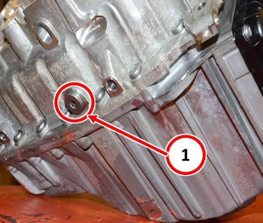
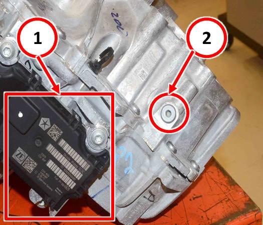
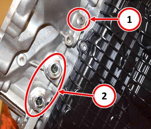
- Remove the transmission drain plug, production fill plug and torque converter pressure port plugs from the bell housing and drain all transmission fluid. See (Fig. 1), (Fig. 2), and (Fig. 3).
Fig. 1 Transmission Fluid Drain Plug
1 – Fluid Drain Plug
Fig. 2 Transmission Production Fill Port
1 – Transmission Control Module (TCM)
2 – Production Fill Port
Fig. 3 Torque Converter Pressure Port
1 – Torque Converter Pressure Port
2 – Transmission Oil Cooler Line Connections
- Remove the transmission electrical connector retaining clip from the valve body oil pan and push the connector slightly into the pan.
- Remove the valve cover oil pan retaining bolts (Qty 7) and remove the pan.
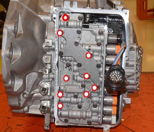
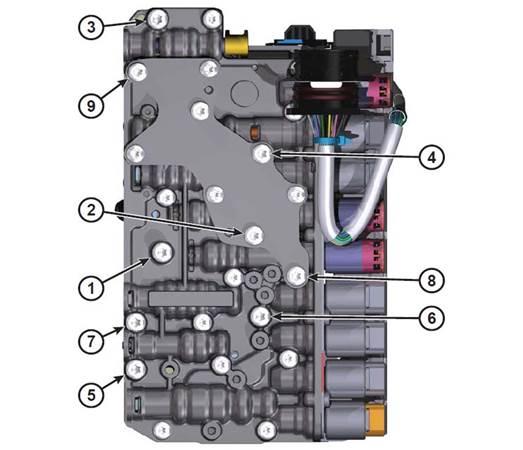
- Remove the valve body retaining bolts securing the valve body assembly to the transmission case. Only 9 bolts will need to be removed in order to remove the valve body. See (Fig. 4).
Fig. 4 Only Remove Bolts Highlighted
CAUTION: Care must be taken when removing the valve body to avoid damage to the Transmission Range Sensor (TRS) and speed sensor electrical harness.
- Using a suitable prying tool, pry the valve body away from the fluid transfer/adapter tubes.
- Taking care not to damage the wiring harness, set the valve body aside to gain access to the TRS and speed sensor bolted to the transmission housing.
- Remove the TRS and speed sensor retaining bolts and remove the sensors.
- Set the valve body aside in a clean area until reinstallation.
- From around the perimeter of the transmission, remove the bellhousing to transmission housing retaining bolts (Qty 17).
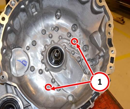
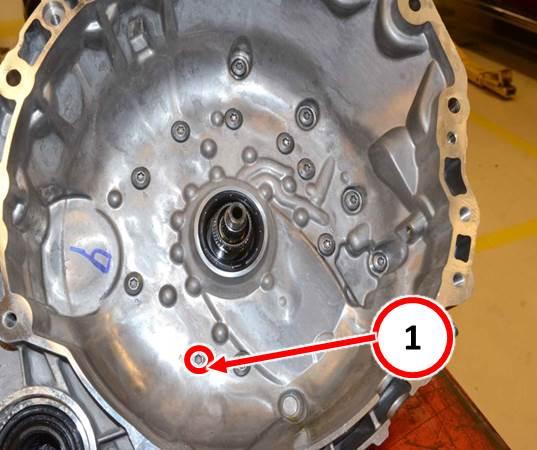
- Remove the inner bellhousing bolts (Qty 11). Do Not remove bolts (1) at this time (Fig. 5).
Fig. 5 Inner Bellhousing Bolts
1 – Do not remove these bolts at this time
- Using wooden blocks to stabilize the transmission on the work surface, position the transmission on the bench with the bellhousing facing upward.
- Using a suitable pry bar in the proper pry location, pry upwards to dislodge the bellhousing from the transmission housing.
- Lift the bellhousing straight upward and separate the assembly from the transmission housing. The E-Clutch, Output Gear Sub Assembly (OPSA), and fluid filter will still be attached to the bellhousing.
- Remove the bellhousing to transmission housing gasket and set aside.
- Remove the differential gear assembly.
- Remove the transfer gear assembly.
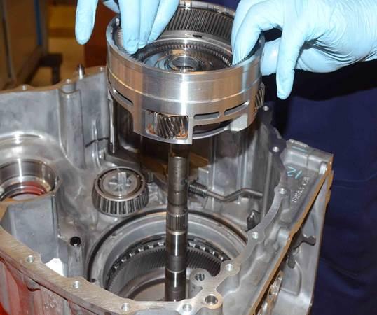
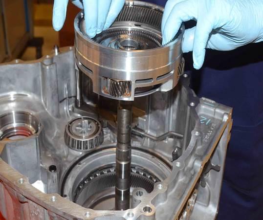
- Remove the Gear 4 Annulus and Planetary Pinion Carrier assembly. See (Fig. 6).
Fig. 6 Gear 4 Planetary Pinion Carrier Assembly
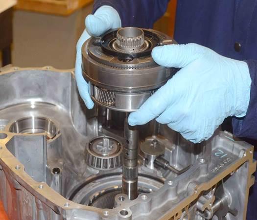
- Remove the Gear 3 Annulus and Carrier Gear assembly. See (Fig. 7).
Fig. 7 Gear 3 Annulus Gear Assembly
NOTE: It may be necessary to use a 1 inch socket between the bearing puller and transmission case for clearance.
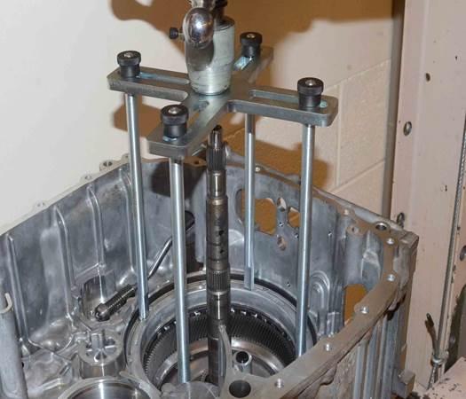
- With the transmission properly supported in a suitable arbor press, install pressing tool 8901A (with the pressure scale removed) and pressing tool adapter 10428 over the D-Clutch piston/retainer. See (Fig. 8).
Fig. 8 Pressing Tool Installed
- Compress the D-Clutch piston retainer assembly and remove the snap ring.
- Remove the pressing tool and place the transmission back onto the work bench.
- Remove the D-Clutch piston retainer, piston, and belleville spring.
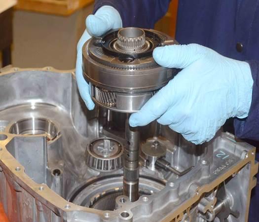
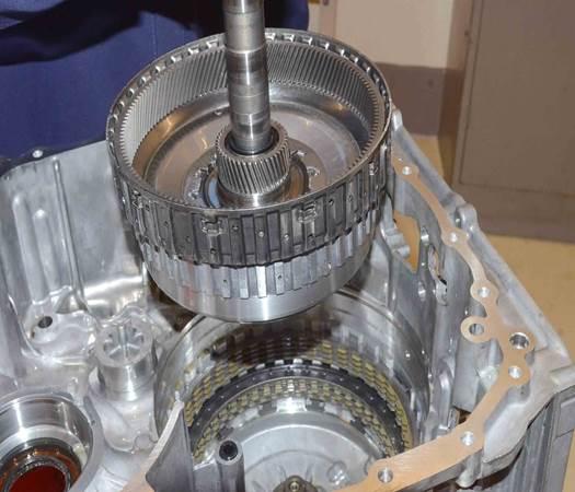
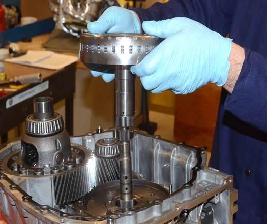
- Remove the gear train assembly (annulus gear 3, B-clutch discs and hub, and input shaft assembly) by lifting upwards on the input shaft. See (Fig. 9). Do not lift the assembly by the hub as this will disengage the hub assembly from the B-Clutch clutch pack.
Fig. 9 Gear Train Assembly
- Remove the D-Clutch clutch pack (plates and fibers).
- Remove the C-Clutch clutch pack selectable snap ring.
- Remove the C-Clutch clutch pack (plates and fibers).
- Install adapter plate 10504 over the C-Clutch belleville spring.
- Properly support the transmission assembly into the arbor press and install pressing tool 8901A (with the pressure scale removed) and pressing tool adapter 10428 on top of the 10504 adapter plate.
- Compress the belleville spring to allow removal of the C-Clutch snap ring.
- Remove the C-Clutch snap ring and discard.
- Remove and discard all differential seals from the transmission housing and bellhousing.
CAUTION: The work area, counter surfaces, and tools must be thoroughly cleaned before attempting to assemble the transmission. All of the sub assemblies should be cleaned and assembled with new sealing components where applicable.
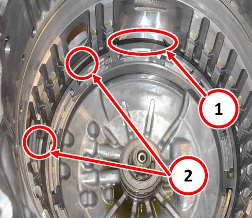
NOTE: The new C-Clutch snap ring will be installed with the opening in a different position from the original.
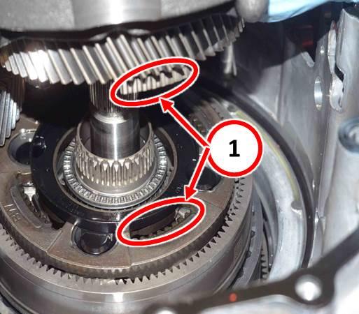
- Install the new snap ring with the opening rotated 90 degrees counter clockwise from the original snap ring location. See (Fig. 10) and (Fig. 11).
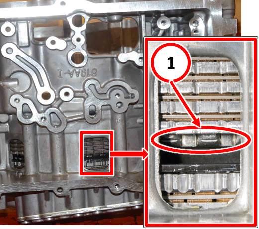
Fig. 10 Snap Ring Orientation
1 – Original snap ring opening installation location
2 – New snap ring opening installation location
Fig. 11 New Snap Ring Installed
- Release pressure on the press and remove the pressing tool and adapter to release the belleville spring.
- Verify the new snap ring is properly seated in the groove.
- Install the C-Clutch clutch pack (plates and fibers) and install the selectable snap ring into the case.
NOTE: The #8 Needle Thrust Bearing may still be attached to the bottom of the gear train hub assembly removed in Step #25. Remove the bearing before installation of the hub assembly.
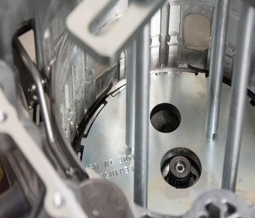
- Verify the #8 Needle Thrust Bearing is properly oriented on the Oil Feed Bushing in the bottom of the case. See (Fig. 12).
Fig. 12 Thrust Bearing Properly Installed
NOTE: Ensure that the friction plate tabs for the C and D clutch packs are aligned to help with proper installation of the gear train assembly.
NOTE: A solid audible clunk will be heard if installed correctly.
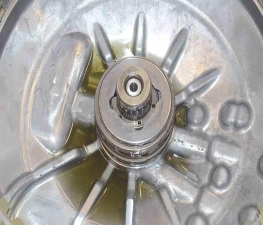
- While not allowing the input shaft to slip inward, wriggle the gear train assembly until it is properly engaged into the C and D-Clutch discs. See (Fig. 13) for proper gear train assembly installation.
Fig. 13 Gear Train Assembly Properly Seated
1 – D-Clutch hub slightly protruding below D-Clutch clutch pack.
NOTE: Closely inspect the D-Clutch piston and piston retainer O-ring seals for damage prior to installation.
- Install the D-Clutch belleville spring, D-Clutch piston, and D-Clutch piston retainer assembly.
- With the transmission properly supported in a suitable arbor press, install pressing tool 8901A and pressing tool adapters (10428).
- Compress the D-Clutch piston retainer until the snap ring grove is exposed.
- Install the D- Clutch piston retainer snap ring.
- Remove the pressing tool and remove the transmission from the arbor press.
- Install the Gear 3 Annulus and Carrier Gear assembly. See (Fig. 14).
Fig. 14 Gear 3 Annulus Gear Assembly
- Install the Gear 4 Annulus and Planetary Pinion Carrier assembly. See (Fig. 15).
Fig. 15 Gear 4 Planetary Pinion Carrier Assembly
- At the bellhousing assembly, remove bolt #2 taking care not to allow the OPSA and E-clutch assembly drop away from the bellhousing. See (Fig. 16).
Fig. 16 OPSA Retaining Bolt
1 – OPSA retaining bolt #2
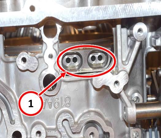
- Separate the OPSA from the E-Clutch and bell housing and install onto the Planetary Pinion Carrier assembly making sure the lower gear teeth are properly meshed with the pinion carrier and transfer tube orifices are properly aligned. See (Fig. 17) and (Fig. 18).
Fig. 17 OPSA To Carrier Installation
1 – Verify lower OPSA gear teeth are properly meshed.
Fig. 18 OPSA Fluid Adapter Tube Orifice Orientation
1 – Transmission Fluid Adapter Tube Orifices
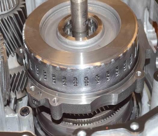
- Remove the E-Clutch clutch pack and hub from the bell housing and while holding the clutch friction discs and fibers in place inside of the hub, install assembly onto the OPSA. See (Fig. 19) and (Fig. 20).
Fig. 19 E Clutch And Hub Installation
Fig. 20 E Clutch And Hub Properly Seated
- Install the transfer gear assembly.
- Install the differential gear assembly.
- Ensure that the transmission fluid port seal is properly installed into the transmission housing before installing the bellhousing. See (Fig. 21).
Fig. 21 Transmission Fluid Port Seal
- Install the bellhousing gasket.
- Carefully lower the bellhousing onto the transmission case. It may be necessary to rotate the OPSA/E-Clutch assembly slightly to assure proper guide pin alignment into the bellhousing during installation. See (Fig. 22) for proper final alignement.
Fig. 22 OPSA To Bellhousing Properly Aligned
1 – Fluid Adapter Tube Orifices Properly Aligned
- Engage the guide pins in the transmission housing into the receptacle holes in the bellhousing to assure proper alignment.
- Install the bellhousing to transmission housing bolts and hand tighten.
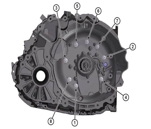
- Install the inner bellhousing bolts and torque, in sequence, to 29 Nm (21 ft. lbs.). See (Fig. 23).
Fig. 23 Inner Bellhousing Bolt Torque Sequence
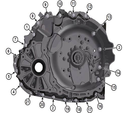
- Torque all remaining bellhousing to transmission case bolts, in sequence, to 29 Nm (21 ft. lbs.). See (Fig. 24).
Fig. 24 Transmission Case Bolt Torque Sequence
NOTE: When the internal components are properly installed and transmission case is torqued, the input shaft end play should be between 1.8 mm to 7.6 mm (0.07 in. to 0.32 in.) and should be able to be rotated with some resistance.
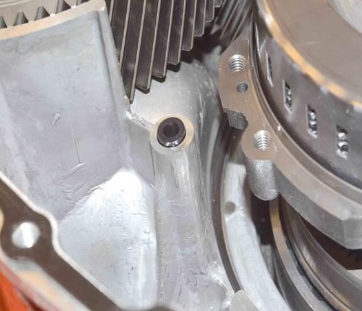
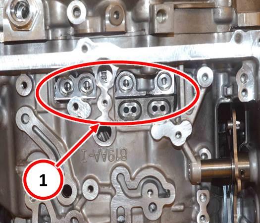
- Install the 6 valve body fluid adapter tubes, using new O-rings, into the transmission. Ensure the 2 oblong adapter tubes are properly oriented. See (Fig. 25).
Fig. 25 Transmission Fluid Adapter Tube Orientation
- Install the 2 larger fluid transfer tubes into the valve body.
- Place the valve body over the transmission and install the TRS and speed sensor. Torque retainer bolts to 6.5 Nm (5 ft. lbs.).
CAUTION: Care must be taken when installing the valve body to avoid damaging the TRS and speed sensor wiring harness.
- Align the valve body over the fluid adapter tubes and, while guiding the manual lever cam into the slot on the manual valve, firmly press the valve body into place.
- Install the valve body retaining bolts and torque, in sequence, to 11Nm (8 ft. lbs.). See (Fig. 26).
Fig. 26 Valve Body Retaining Bolt Torque Sequence
NOTE: A light coating of assembly lube can be applied to the O-ring seals of the valve body wiring harness electrical connector to ease installation.
- Place the valve body cover over the valve body and press the harness connector into the cover until the retainer clip groove is exposed.
- Install the electrical harness connector retaining clip.
- Install the valve body fluid cover and torque the retaining bolts to 11 Nm (8 ft. lbs.)
- Install the transmission. Refer to detailed installation instructions in
DealerCONNECT/TechCONNECT Service Information Section 21 – Transmission and Transfer Case> Automatic – 948TE> Installation> FWD, AWD/4WD.
- Fill the transmission to the proper fluid level. Refer to detailed filling instructions inDealerCONNECT/TechCONNECT Service Information Section 21 – Transmission and Transfer Case> Automatic – 948TE> Fluid and Filter> Standard Procedure> Fluid Level Check.
- Is your vehicle a 2014 KL?
- Yes>>> Perform the 9 speed Adaptation Drive Learn procedure. Refer to all applicable published service bulletins regarding the adaptation drive learn for detailed procedures and labor times. Proceed to Step #79.
- No>>> Proceed to Step #71.
- Start the engine and monitor the transmission temperature on the Electronic Vehicle Information Center (EVIC).
- With the vehicle located in a suitable area, allow the transmission to warm up to minimum of 60°C (140°F) by performing the following steps:
- Apply the service brake.
- Shift Transmission from Park to Reverse.
- Shift Transmission from Reverse to Drive.
- Accelerate the vehicle to minimum of 45 mph to allow the transmission to cycle through each gear.
- Continue to drive the vehicle until the transmission temperature reaches 60°C(140°F).
NOTE: If the vehicle is equipped with the start/stop feature (sales code XBU) it must be disabled prior to performing this procedure. To disable, press the on/off switch located on the center switch bank near the HVAC controls.
- Connect wiTECH diagnostic scan too to the vehicle.
- Check for active TCM DTCs (Diagnostic Trouble Codes). Do not perform the Quick Learn procedure if TCM DTCs are present. Repair transmission as required.
- Select the TCM module in wiTECH.
- Select the “Misc Functions” tab.
NOTE: If the “Quick Learn” option does not appear on wiTECH and both the TCM and PCM were just updated, restart the wiTECH application which should now be populated with the “Quick Learn” option.
- Select the “Quick Learn” procedure, and follow the on-screen instructions to reset andlearn the clutch adaptive values.
- Shift the transmission into Park and shut off the engine. Proceed to Step #79.
- Procedure complete.
POLICY:
Reimbursable within the provisions of the warranty.
TIME ALLOWANCE:
| Labor Operation No: | Description | Skill Category | Amount |
|---|---|---|---|
| 21-00-04-95 | Snap Ring, Transmission C-Clutch – Replace (2.4L KL Only Includes Transmission Removal And Installation) (3 – Highly Skilled) | 2 – Automatic Transmission | ** 6.5 Hrs ** |
| 21-00-04-96 | Snap Ring, Transmission C-Clutch – Replace (3.2L KL Only Includes Transmission Removal And Installation) (3 – Highly Skilled) | 2 – Automatic Transmission | ** 6.6 Hrs ** |
| 21-00-04-97 | Snap Ring, Transmission C-Clutch – Replace (2.4L UF Only Includes Transmission Removal And Installation) (3 – Highly Skilled) | 2 – Automatic Transmission | ** 7.7Hrs ** |
| Related Op. | |||
| 21-00-04-50 | 9-Spd 948TE Transmission Quick Learn Procedure | 2 – Automatic Transmission | 0.4 Hrs |
| Opt. Equip. | |||
| 21-00-04-63 | All-Wheel Drive Equipped (3.2L Equipped) | 2 – Automatic Transmission | 1.5 Hrs |
| 21-00-04-66 | All-Wheel Drive Equipped (2.4L Equipped) | 2 – Automatic Transmission | 3.2 Hrs |
| 21-00-04-67 | Skid Plate Equipped | 2 – Automatic Transmission | 0.4 Hrs |
FAILURE CODE:
| ZZ | Service Action |
NUMBER: 21-008-15 REV. B
GROUP: Transmission and Transfer Case
DATE: August 15, 2015
 Loading...
NUMBER: 21-008-15 REV. A
GROUP: Transmission and Transfer Case
DATE: February 07, 2015
 Loading...
 .oemdtc.com/wp-content/plugins/embed-any-document/images/reload.svg" alt="Reload" width="12" height="12" title="Transmission Shift Quality C-Clutch Snap Ring - 2014-2015 Jeep Cherokee & 2015 Chrysler 200 31"> Reload document
NUMBER: 21-008-15
GROUP: Transmission and
Transfer Case
DATE: February 05, 2015
 Loading...
- Fits: 2013-2015 Ram
 1500 3.6L,2013-2015 Ram
 1500 5.7L,2014-2015 Ram
 1500 3.0L,2014-2015 Jeep Grand Cherokee 6.4L,2014-2015 Jeep Grand Cherokee 5.7L,2014-2015 Jeep Grand Cherokee 3.0L,2014-2015 Jeep Grand Cherokee 3.6L,2014-2015 Jeep Cherokee 3.2L,2014-2015 Dodge
 Durango 5.7L,2014-2015 Jeep Cherokee 2.4L,2012-2013 Chrysler 300 3.6L,2013-2015 Dodge
 Charger 3.6L
 - Genuine Automatic Transmission Fluid
- Fits: 2013-2015 Ram
 1500 3.6L,2013-2015 Ram
 1500 5.7L,2014-2015 Ram
 1500 3.0L,2014-2015 Jeep Grand Cherokee 6.4L,2014-2015 Jeep Grand Cherokee 5.7L,2014-2015 Jeep Grand Cherokee 3.0L,2014-2015 Jeep Grand Cherokee 3.6L,2014-2015 Jeep Cherokee 3.2L,2014-2015 Dodge
 Durango 5.7L,2014-2015 Jeep Cherokee 2.4L,2012-2013 Chrysler 300 3.6L,2013-2015 Dodge
 Charger 3.6L
 - Fits: 2013-2015 Ram
 1500 3.6L,2013-2015 Ram
 1500 5.7L,2014-2015 Ram
 1500 3.0L,2014-2015 Jeep Grand Cherokee 6.4L,2014-2015 Jeep Grand Cherokee 5.7L,2014-2015 Jeep Grand Cherokee 3.0L,2014-2015 Jeep Grand Cherokee 3.6L,2014-2015 Jeep Cherokee 3.2L,2014-2015 Dodge
 Durango 5.7L,2014-2015 Jeep Cherokee 2.4L,2012-2013 Chrysler 300 3.6L,2013-2015 Dodge
 Charger 3.6L
 - Sty needed per vehicle: 1
- Advanced OEM grade synthetic formulation designed for modern 6, 7, 8 and 9 ZF speed automatic transmissions found in most European, Asian and US vehicles; excellent cold temperature performance down to - 60 F
- Compatible with a wide range of transmissions (see specs below) and a very wide range of other vehicles requiring a low viscosity, enhanced durability fluid
- Possesses excellent frictional characteristics for smoother shifting and quieter operation; very high viscosity index for superior viscosity stability; eliminates notchy shifting, smooth, rapid shifting even in high torque, conditions
- Provides a wide range of seal compatibility with all types of materials; superb high temperature performance in high ambient temperatures and will not thin out
- PAO blended fluid with enhanced thermal stability and durability; this fluid qualifies as FILL FOR LIFE (300,000 + Miles) capabilities in sealed transmissions in passenger cars and SUVs; once you change it, you should not have to change it again
- Part Number: 68375013AA,68259546AA,68375014AA,68259547AA.
- Partslink Number : CH1043126, CH1042126.
- Fits: Compatible with Dodge
 Challenger 2015 2016 2017 2018,Driver & Passenger Side.
 - Function: The front bumper bracket retainer is set to repair your damaged or old side bracket retainer mounting cover support. Fix the vehicle bumper, assist the bumper to absorb and reduce the external impact, and protect the front of the body.
- Material: The bumper cover support bracket is made of high-quality ABS plastic, which is durable and has a very long service life. It adopts advanced manufacturing technology, with high strength, good toughness, and is not easy to deform and fracture.
- Mopar OEM part that fits your specific vehicle
- INSULATOR ENGINE MOUNT
- Part Number: 68252518AA
- Manufactured to meet specifications for fit, form, and function
- Vehicle Specific
- Manufacturer Warranty
- Chrysler Quality Assured
- OEM, Not After Market
- Mopar OEM part that fits your specific vehicle
- INSULATOR ENGINE MOUNT
- Part Number: 68252522AA
- Manufactured to meet specifications for fit, form, and function
- Mopar OEM part that fits your specific vehicle
- COVER BATTERY POST
- Part Number: 68164628AA
- Manufactured to meet specifications for fit, form, and function
- Genuine Mopar Exhaust Seal - 68350252AA
- Item Package Weight - 0.1 Pounds
- Item Package Quantity - 1
- Product Type - GASKETS
- Wide Compatibility --- This temperature sensor Compatible with Chrys-ler Ram
 Jee-p Do-dge 2014- 2022.
 - Part Numbers ---68164627AA.
- Cost-effective --- Manufacturer direct supply, quality assurance.
- Premium Quality --- The temperature sensor is made of high quality quality materials to ensure a reliable repair and a long service life.
- Note---Please make sure that the model number, part number and photo is the same as yours before order.
Last update on 2025-05-09 / Affiliate links / Images from Amazon Product Advertising API
This product presentation was made with AAWP plugin.
