| “This site contains affiliate links for which OEMDTC may be compensated” |
NUMBER: 10-001-15
GROUP: Restraints
DATE: May 16, 2015
THIS SERVICE BULLETIN IS ALSO BEING RELEASED AS RAPID RESPONSE TRANSMITTAL (RRT) 15-054. ALL APPLICABLE SOLD AND UN-SOLD RRT VIN’s HAVE BEEN LOADED. TO VERIFY THAT THIS RRT SERVICE ACTION IS APPLICABLE TO THE VEHICLE, USE VIP OR PERFORM A VIN SEARCH IN TECHCONNECT. ALL REPAIRS ARE REIMBURSABLE WITHIN THE PROVISIONS OF WARRANTY.
SUBJECT:
Intermittent Seat Belt Chime And Seat Belt Indicator Lamp On
OVERVIEW:
This bulletin involves replacing both right and left front seatbelt buckle covers.
MODELS:
NOTE: This bulletin applies to vehicles built on or after August 11, 2014 (MDH 0811XX) and on or before September 5, 2014 (MDH 0905XX).
SYMPTOM/CONDITION:
The Customer may describe seat belt buckle indicator lamp on and/or chime tone sound when seatbelt is buckled.
DIAGNOSIS:
If a customer’s VIN is listed in VIP or your RRT VIN list, perform the repair. For all other customers that describe the symptom/condition listed above, perform the Repair Procedure.
PARTS REQUIRED:
| Qty. | Part No. | Description |
|---|---|---|
| 1 (AR) | 6BT66DX9AA | Cover, Buckle Kit, Sales Code DX9 Black |
| 1 (AR) | 6BT66ML2AA | Cover, Buckle Kit, Sales Code ML2 Linen |
| 1 (AR) | 6BT66LC5AA | Cover, Buckle Kit, Sales Code LC5 Indigo |
| 1 (AR) | 6BT66LU5AA | Cover, Buckle Kit, Sales Code LU5 Jeep Brown Brown |
SPECIAL TOOLS/EQUIPMENT REQUIRED:
| NPN | T10 Tamper Resistant 6-Point Star Driver |
REPAIR PROCEDURE:
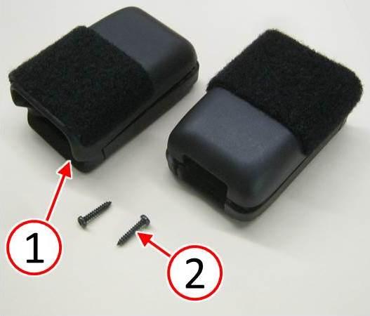
The seatbelt buckle cover kit will contain two covers and two screws. Retain and reuse the original buckle cover screws where possible. The two screws provided in the kit are for replacement of any lost or damaged screws (Fig. 1).
Fig. 1 Seatbelt Buckle Cover Replacement Kit Contents
1 – Buckle Cover
2 – Screws
- Disconnect and isolate the negative cable from the battery. If equipped with an Intelligent Battery Sensor (IBS), disconnect the IBS connector before disconnecting the negative cable from the battery. Wait two minutes for the system capacitor to discharge before further service.
- Lower the seat for better access to the buckle.
NOTE: Make certain to retain both screws for installation.
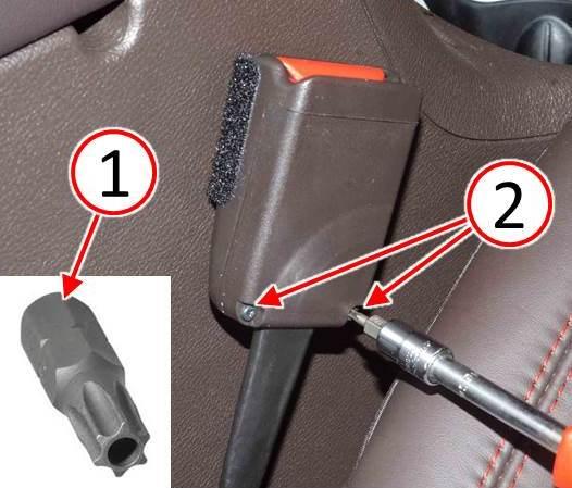
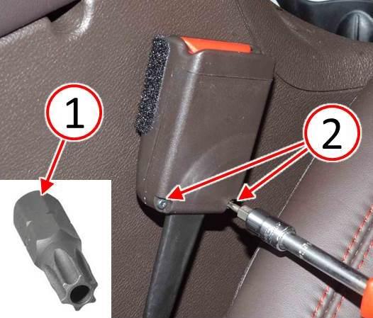
- Remove the two screws (2) from the lower buckle cover using a T10 tamper resistant 6-point star driver (1) (Fig. 2).
Fig. 2 Remove Seatbelt Buckle Cover Screws
1 – T10 Tamper Resistant 6-Point Star Driver
2 – Screws
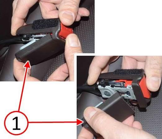
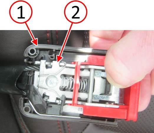
- Remove the lower buckle cover (outboard side) as follows:
- Hold the upper cover with one hand.
- Using the other hand, place a finger at the rear edge of the lower cover (1) and tilt the lower cover away from the buckle (Fig. 3).
- Discard the lower cover – do not reuse.
Fig. 3 Remove Seatbelt Buckle Lower Cover
1 – Lower Cover
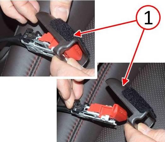
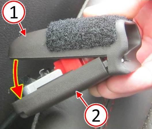
- Remove the upper buckle cover (inboard side) as follows:
- Lift the upper cover (1) up and away from the buckle (Fig. 4).
- Discard the upper cover – do not reuse.
Fig. 4 Remove Seatbelt Buckle Upper Cover
1 – Upper Cover
- Install a NEW lower cover (1). Cover should fit “snug” to the buckle mechanism (2) (Fig. 5).
Fig. 5 Install NEW Seatbelt Buckle Lower Cover
1 – Lower Cover
2 – Seatbelt Buckle Mechanism
NOTE: If excessive effort is required to install the upper cover, more than light finger pressure, then the covers are not properly aligned. Remove the covers and check alignment, then reassemble.
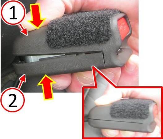
- Install a NEW upper cover (1) to the NEW lower cover (2) by rocking and snapping the upper cover back into place (Fig. 6) and (Fig. 7).
Fig. 6 Install NEW Seatbelt Buckle Upper Cover
1 – Upper Cover
2 – Lower Cover
Fig. 7 Snap Seatbelt Buckle Covers Together
1 – Upper Cover
2 – Lower Cover
- Using a T10 tamper resistant 6-point star driver (1), install the screws (2) (Fig. 8) and tighten the screws by hand to 0.3 N·m (2.9 in. lbs.).
- Inspect that both screw heads are fully seated against the lower cover.
Fig. 8 Install Seatbelt Buckle Cover Screws
1 – T10 Tamper Resistant 6-Point Star Driver
2 – Screws
- Check the buckle function five times by using the seatbelt latch. Insert and release the latch and check for normal operation.
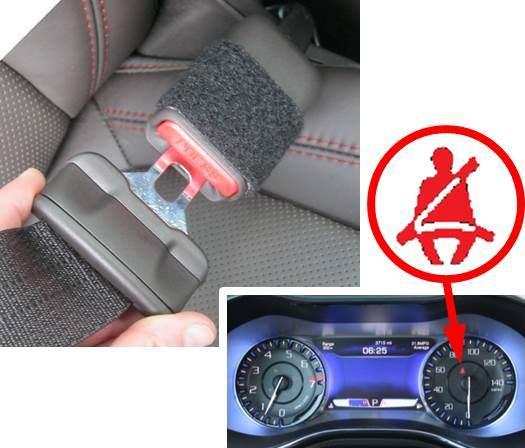
- If the seatbelt buckle fails to function properly or the seatbelt indicator fails to turn off,normal diagnosis should be performed (Fig. 9).
Fig. 9 Test Seatbelt Buckle For Proper Function
POLICY:
Reimbursable within the provisions of the warranty.
TIME ALLOWANCE:
| Labor Operation No: | Description | Skill Category | Amount |
|---|---|---|---|
| 23-13-01-90 | Replace Both Front Seatbelt Buckle Covers (1 – Semi-Skilled) | 6 – Electrical and Body Systems | 0.2 Hrs. |
FAILURE CODE:
| ZZ | Service Action |
 Loading...
