| “This site contains affiliate links for which OEMDTC may be compensated” |
NUMBER: 08-089-15
GROUP: Electrical
DATE: September 19, 2015
SUBJECT:
Security System Nuisance Alarms
OVERVIEW:
This bulletin involves replacing the five alarm sensor transmitters.
MODELS:
| 2011 – 2015 | (JK) | Jeep Wrangler Wrangler |
NOTE: This bulletin applies to vehicles within the following markets/countries:
United Kingdom (UK) Only
NOTE: This bulletin applies to vehicles built on or before August 14, 2015 (MDH 0814XX) equipped with Premium Security Alarm (Sales Code LSC) and Thatcham Security Equipment (Sales Code LS9).
SYMPTOM/CONDITION:
The customer may describe the security system nuisance alarms with no apparent cause for activation.
DIAGNOSIS:
If the customer describes the symptom/condition listed above, perform the Repair Procedure.
PARTS REQUIRED:
| Qty. | Part No. | Description |
|---|---|---|
| 5 | 68064378AC | Transmitter, Alarm Sensor |
| 1 (AR) | NPN | 3M™ #06383 Automotive Acrylic Plus Attachment Tape or equivalent |
| 1 (AR) | NPN | 3M™ #06396 Adhesion Promoter or equivalent |
NOTE: 3M™ #06383 Automotive Acrylic Plus Attachment Tape will service approximately 150 vehicles. 3M™ #06396 Adhesion Promoter will service 1 vehicle per packet.
SPECIAL TOOLS/EQUIPMENT REQUIRED:
| C-4755 | Trim Stick (Originally Shipped In Kit Numbers 9299, 9299CC, 9299CC, 9300A-CAN) |
NOTE: The Trim Stick is a non-reimbursable shop tool.
REPAIR PROCEDURE:
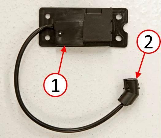
- Replace all five alarm sensor transmitters per the following procedure (Fig. 1). Two are located in the instrument panel, two in the center console, and one behind the left rear quarter interior trim panel.
Fig. 1 Ultrasonic Sensor
1 – Alarm Sensor
2 – Alarm Sensor Microphone
- Disconnect and isolate the negative battery cable.
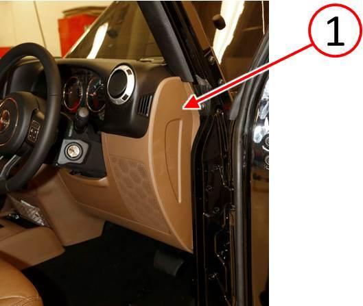
- Using a trim stick, remove the instrument panel right side end cap (Fig. 2).
Fig. 2 Instrument Panel Right Side End Cap
1 – Instrument Panel End Cap
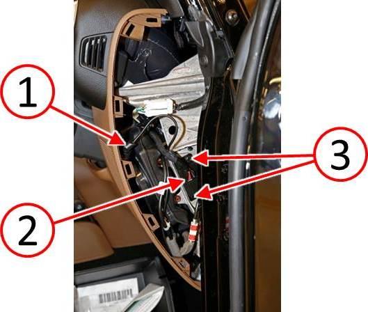
- Remove the alarm sensor microphone (1) from the reflector cone, located on the back side of the speaker grille (Fig. 3).
- Disconnect the electrical connector (2) from the alarm sensor (Fig. 3).
- Remove the two fasteners (3) securing the alarm sensor (Fig. 3).
- Remove the alarm sensor and replace with a NEW alarm sensor from the Parts Required table.
- Install the two fasteners (3) securing the alarm sensor (Fig. 3).
- Connect the electrical connector (2) to the alarm sensor (Fig. 3).
NOTE: Ensure the correct direction orientation of the alarm sensor microphone for proper functionality.
- Install the alarm sensor microphone (1) to the reflector cone, located on the back side of the speaker grille (Fig. 3).
- Install the instrument panel right side end cap (Fig. 2).
Fig. 3 Instrument Panel Right Side Alarm Sensor
1 – Alarm Sensor Microphone
2 – Electrical Connector
3 – Fasteners
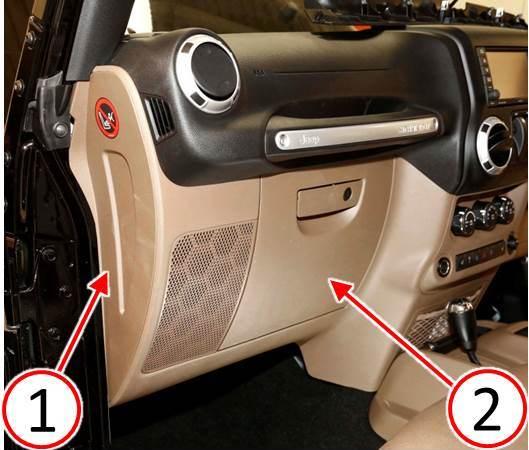
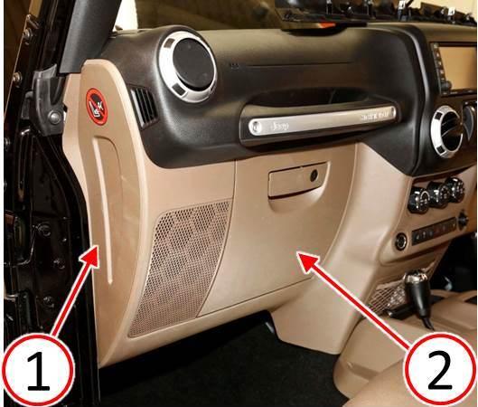
- Using a trim stick, remove the instrument panel left side end cap (Fig. 4).
- Remove the glove box (2) (Fig. 4). Refer to the detailed service procedures available in DealerCONNECT> TechCONNECT under: Service Info> 23 – Body> Instrument Panel> GLOVE BOX, Instrument Panel> Removal.
Fig. 4 Instrument Panel Left Side End Cap And Glove Box
1 – Instrument Panel End Cap
2 – Glove Box
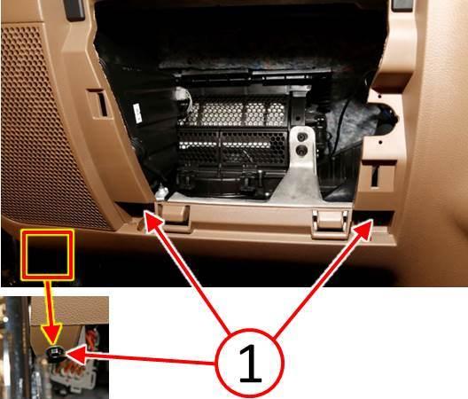
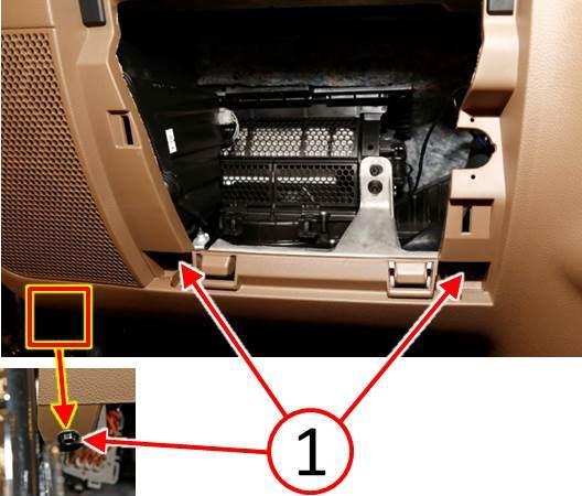
- Remove the three fasteners (1) attaching the lower left side of the instrument panel cover (Fig. 5).
Fig. 5 Instrument Panel Left Side Fasteners
1 – Fasteners
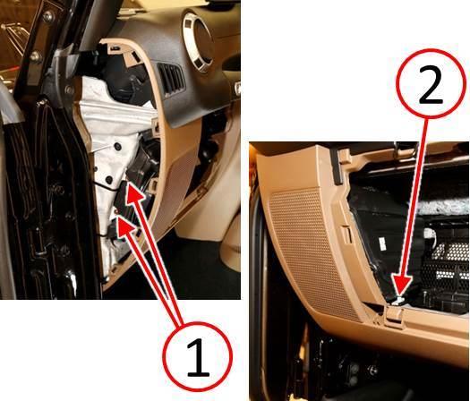
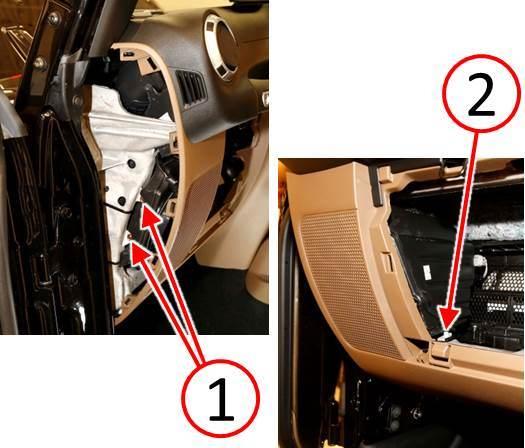
- Remove the left speaker mounting fasteners. Two fasteners (1) are located at the left side of the instrument panel and one fastener (2) is located at the lower left corner of the glove box opening (Fig. 6).
Fig. 6 Instrument Panel Left Side Speaker Fasteners
1 – Speaker Fasteners
2 – Speaker Fastener
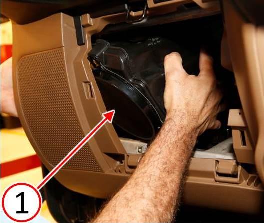
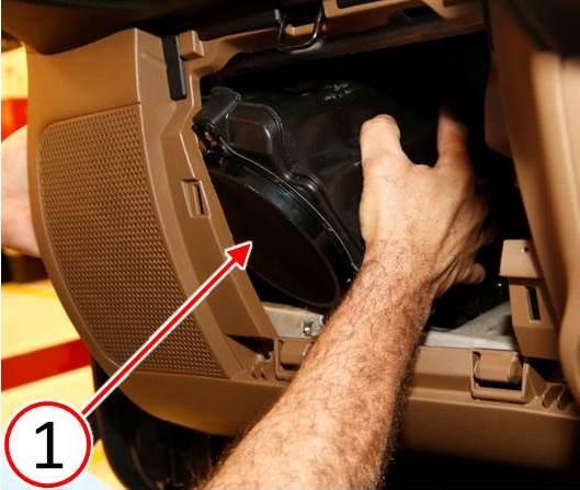
- Remove the left speaker by carefully pulling the left side of the instrument panel cover outward until there is sufficient room to remove the speaker (1) through the glove box opening (Fig. 7).
Fig. 7 Instrument Panel Left Side Speaker
1 – Speaker
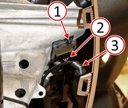
- Remove the alarm sensor microphone (3) from the reflector cone, located on the backside of the speaker grille (Fig. 8).
- Disconnect the electrical connector (2) from the alarm sensor (Fig. 8).
- Remove the two fasteners (1) securing the alarm sensor (Fig. 8).
- Remove the alarm sensor and replace with a NEW alarm sensor from the Parts Required table.
- Install the two fasteners (1) securing the alarm sensor (Fig. 8).
- Connect the electrical connector (2) to the alarm sensor (Fig. 8).
NOTE: Ensure the correct direction orientation of the alarm sensor microphone for proper functionality.
- Install the alarm sensor microphone (3) to the reflector cone, located on the back sideof the speaker grille (Fig. 8).
Fig. 8 Instrument Panel Left Side Alarm Sensor
1 – Fasteners
2 – Electrical Connector
3 – Alarm Sensor Microphone
- Install the left speaker through the glove box opening while carefully pulling the left side of the instrument panel cover outward, until there is sufficient room to insert the speaker (1) into position (Fig. 9).
Fig. 9 Instrument Panel Left Side Speaker
1 – Speaker
- Install the left speaker mounting fasteners. Two fasteners (1) are located at the left side of the instrument panel and one fastener (2) is located at the lower left corner of the glove box opening (Fig. 10).
Fig. 10 Instrument Panel Left Side Speaker Fasteners
1 – Speaker Fasteners
2 – Speaker Fastener
- Install the three fasteners (1) attaching the lower left side of the instrument panel cover (Fig. 11).
Fig. 11 Instrument Panel Left Side Fasteners
1 – Fasteners
- Install the glove box (2) to the instrument panel (Fig. 12). Refer to the detailed service procedures available in DealerCONNECT> TechCONNECT under: Service Info> 23 Body> Instrument Panel> GLOVE BOX, Instrument Panel> Removal.
- Install the left side end cap (1) to the instrument panel (Fig. 12).
Fig. 12 Instrument Panel Left Side End Cap And Glove Box
1 – Instrument Panel End Cap
2 – Glove Box
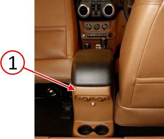
- Using a trim stick, release the rear center console bezel (1) and tilt the bezel downward (Fig. 13).
Fig. 13 Center Console End Cap
1 – Center Console Bezel
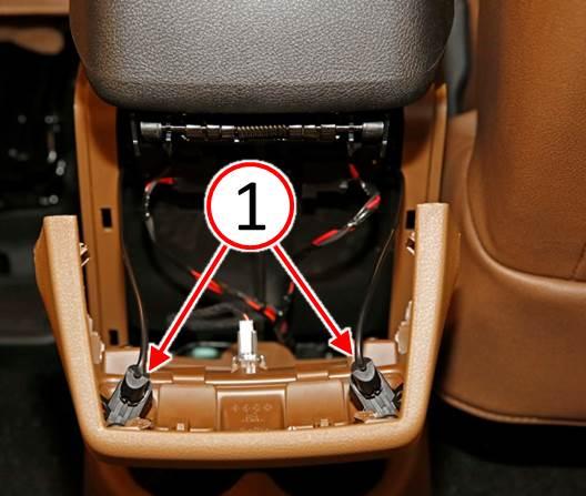
- Remove the alarm sensor microphones (1) from the reflector cones, located on the back side of the center console bezel (Fig. 14).
Fig. 14 Center Console Alarm Sensor Microphone
1 – Alarm Sensor Microphone
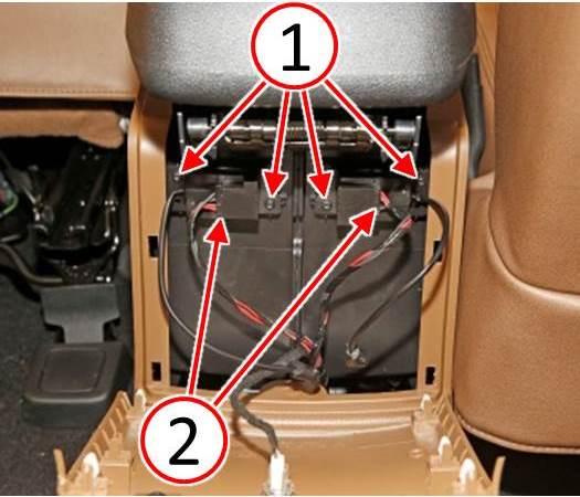
- Disconnect the electrical connectors (2) from the alarm sensors (Fig. 15).
- Remove the four fasteners (1) securing the alarm sensors (Fig. 15).
- Remove the alarm sensors and replace with a NEW alarm sensors from the Parts Required table.
- Install the four fasteners (1) securing the alarm sensors (Fig. 15).
- Connect the electrical connectors (2) to the alarm sensors (Fig. 15).
Fig. 15 Center Console Alarm Sensor
1 – Fasteners
2 – Electrical Connectors
- Install the alarm sensor microphones to the reflector cones, located on the back side of the center console bezel (Fig. 14).
- Install the rear center console bezel to the rear center console (Fig. 13).
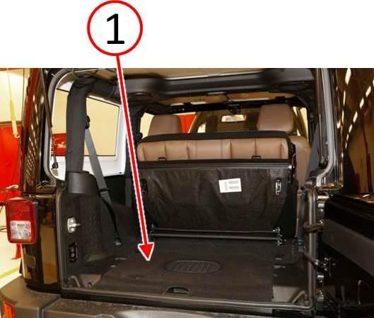
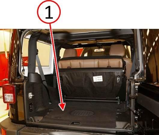
- Remove the load floor panel (1) from the rear compartment (Fig. 16).
Fig. 16 Rear Compartment Load Floor Panel
1 – Load Floor Panel
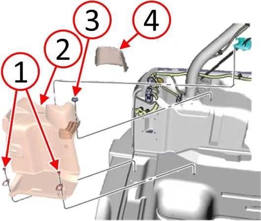
- Remove the fasteners (1) and tie-down clips from the left rear quarter trim panel (Fig. 17).
- Remove the trim cover (4) from the left rear quarter trim panel (Fig. 17).
- Remove the fastener (3) from the left rear quarter trim panel (Fig. 17).
- Remove the left rear quarter trim panel (2) and disconnect the electrical connector from the alarm sensor attached to the back side of the quarter trim panel (Fig. 17).
Fig. 17 Interior Trim Panel Left Rear Corner
1 – Fasteners
2 – Trim Cover
3 – Fastener
4 – Quarter Trim Panel
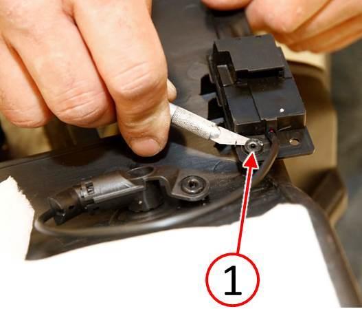
- Using a suitable tool, remove the heat stakes (1) securing the alarm sensor to the quarter trim panel (Fig. 18).
Fig. 18 Cut Heat Stakes And Remove Alarm Sensor
1 – Heat Stakes
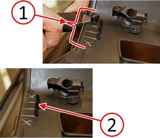
- Trim away the part of the two heat stake studs and three plastic alarm sensor support ribs (1) leaving only the tall shark fin portion (2) of the three ribs (Fig. 19).
Fig. 19 Remove Alarm Sensor Spacer Ribs And Heat Stake Studs
1 – Heat Stake Studs And Support Ribs
2 – Shark Fins
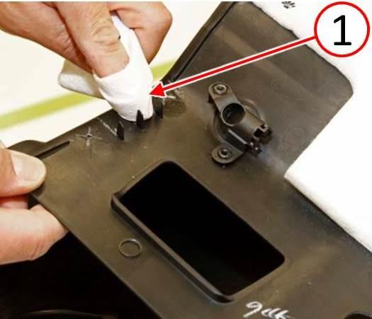
- Using a clean cloth (2), clean the trimmed area with isopropyl alcohol, then apply 3M™ adhesion promoter or equivalent to the trimmed area (Fig. 20).
Fig. 20 Clean Alarm Sensor Mounting Surface
1 – Clean Cloth
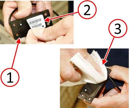
- Remove the label (2) from the back side of the alarm sensor (1) in order to improve adhesion of the sensor to the trim panel (Fig. 21).
- Using a clean cloth (3), clean the back side of the alarm sensor with isopropyl alcohol,then apply 3M™ adhesion promoter or equivalent to the back side of the alarm sensor (Fig. 21).
Fig. 21 Remove Label And Clean Alarm Sensor
1 – Alarm Sensor
2 – Label
3 – Clean Cloth
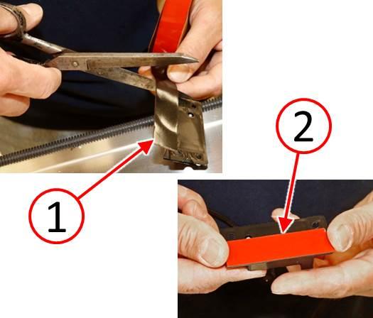
- Using scissors or equivalent cutting tool, cut one piece of 3M™ automotive acrylic plus attachment tape (1) the full length of the alarm sensor (Fig. 22).
- Apply the piece of 3M™ automotive acrylic plus attachment tape (2) to the top edge ofthe alarm sensor (Fig. 22).
Fig. 22 Apply Attachment Tape To Alarm Sensor
1 – Attachment Tape
2 – Tape Piece
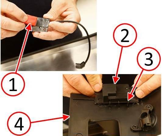
- Remove the backing film (1) from the attachment tape (Fig. 23).
- Align the alarm sensor (2) in its original location on the quarter trim panel (4) againstthe shark fins (3) (Fig. 23).
Fig. 23 Remove Tape Backing And Align Alarm Sensor
1 – Backing Film
2 – Alarm Sensor
3 – Shark Fins
4 – Quarter Trim Panel
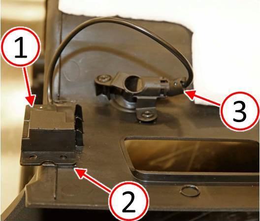
- Press the alarm sensor (1) firmly to the quarter trim panel ensuring complete contact of the attachment tape (2) (Fig. 24).
- Install the alarm sensor microphone (3) to the reflector cone (Fig. 24).
Fig. 24 Install Alarm Sensor And Microphone
1 – Alarm Sensor
2 – Attachment Tape
3 – Alarm Sensor Microphone
- Connect the electrical connector to the alarm sensor attached to the back side of the quarter trim panel, then install the left rear quarter trim panel (2) to the vehicle (Fig. 25).
- Install the fastener (3) to the left rear quarter trim panel (Fig. 25).
- Install the trim cover (4) to the left rear quarter trim panel (Fig. 25).
- Install the fasteners (1) and tie-down clips to the left rear quarter trim panel (Fig. 25).
Fig. 25 Interior Trim Panel Left Rear Corner
1 – Fasteners
2 – Trim Cover
3 – Fastener
4 – Quarter Trim Panel
- Install the load floor panel (1) to the rear compartment (Fig. 26).
Fig. 26 Rear Compartment Load Floor Panel
1 – Load Floor Panel
- Connect the negative battery cable.
POLICY:
Reimbursable within the provisions of the warranty.
TIME ALLOWANCE:
| Labor Operation No: | Description | Skill Category | Amount |
|---|---|---|---|
| 08-20-16-95 | Replace Five Ultrasonic Sensors (1 Semi- Skilled) | 6 – Electrical and Body Systems | 1.0 Hrs. |
FAILURE CODE:
| ZZ | Service Action |
PART REIMBURSEMENT DETAIL:
| Part No: | Description |
|---|---|
| NPN | 3M™ #06383 Automotive Acrylic Plus Attachment Tape or equivalent |
| NPN | 3M™ #06396 Adhesion Promoter Wipe or equivalent |
NOTE: This part number is for reimbursement only and will need to be claimed for 1/150 the value of the 3M™ #06383 Attachment Tape or it will be rejected. If this is a non-MOPAR part or product, a copy of the invoice showing the purchase of the non-MOPAR part or product needs to be attached to the reimbursement claim.
NOTE: This part number is for reimbursement only and will need to be claimed for a single 3M™ #06396 Adhesion Promoter Wipe or it will be rejected. If this is a non-MOPAR part or product, a copy of the invoice showing the purchase of the non-MOPAR part or product needs to be attached to the reimbursement claim.
 Loading...

