| “This site contains affiliate links for which OEMDTC may be compensated” |
NHTSA Campaign Number: 15V468
Manufacturer Chrysler (FCA US LLC)
Components SUSPENSION
Potential Number of Units Affected 199
A reduction of suspension stability control could affect control of the vehicle, increasing the risk of a crash.
Summary
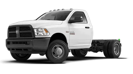
Chrysler (FCA US LLC) is recalling certain model year 2015 Ram
 4500, and 5500 pickup trucks manufactured January 30, 2015, to February 6, 2015. The affected vehicles may have inadequate penetration of the front upper control arm loop to spacer weld, reducing the front suspension stability.
Remedy
Chrysler will notify owners, and dealers will inspect and replace any affected upper control arms, free of charge. The recall began on September 17, 2015. Owners may contact Chrysler
 customer service at 1-800-853-1403. Chrysler
 ’s number for this recall is R34.
Notes
Owners may also contact the National Highway Traffic Safety Administration Vehicle Safety Hotline at 1-888-327-4236 (TTY 1-800-424-9153), or go to www.safercar.gov.
Check if your Vehicle has a Recall
Dealer Service Instructions for:
September 2015
Safety Recall R34 / NHTSA 15V-468 Front Suspension Upper Control Arms
Models
| 2015 | (DP) | RAM Truck (4500 and 5500 series) (4500 and 5500 series) |
NOTE: This recall applies only to the above vehicles built from January 30, 2015 through February 06, 2015 (MDH 013013 through 020602).
Subject
The front suspension upper control arms on about 190 of the above vehicles may have been improperly welded during the manufacturing process. The weld connecting the bushing loop to the upper control arm could break under certain driving conditions. A broken upper control arm could cause a loss of vehicle stability and/or a crash without warning.
Repair
Both front suspension upper control arms must be replaced.
Parts Information
| Description | Part Number |
|---|---|
| Arm, Upper Control (order 2 per vehicle) | 52855625AB |
| Bolt, Upper Control Arm (order 2 per vehicle) | 06104289AA |
| Bolt, Upper Control Arm (order 2 per vehicle) | 06104283AA |
| Nut, Upper Control Arm (order 4 per vehicle) | 06104720AA |
Each dealer to whom vehicles in the recall were assigned will receive enough parts to service about 20% of those vehicles.
For Diesel engine equipped vehicles, order one of each of the parts listed below:
| Description | Part Number |
|---|---|
| Gasket, Front Exhaust Pipe-to-Diesel Particulate Filter (DPF) | 52122213AB |
| Ring, Turbocharger-to-Front Exhaust Pipe Seal | 68071676AA |
| Clamp, Turbocharger-to-Front Exhaust Pipe | 52121859AD |
Parts Return
Please make sure to retain this part until the recall claim is paid and the parts disposition has been determined. This recall part will be subject to parts return.
Special Tools
No special tools are required to perform this service procedure.
Service Procedure
A. Front Suspension Upper Control Arms (equipped with gas engine)
CAUTION: Only replace one upper control arm at a time to maintain front end alignment.
- Raise and support the vehicle on an appropriate drive-on hoist.
CAUTION: New nuts and bolts must be used when replacing the front suspension upper control arms. Discard the original nuts and bolts.
- Using Mopar Rust Penetrating Oil, spray the four exhaust manifold nuts and bolts.
- Use the following procedure to replace the right side front suspension upper control arm:
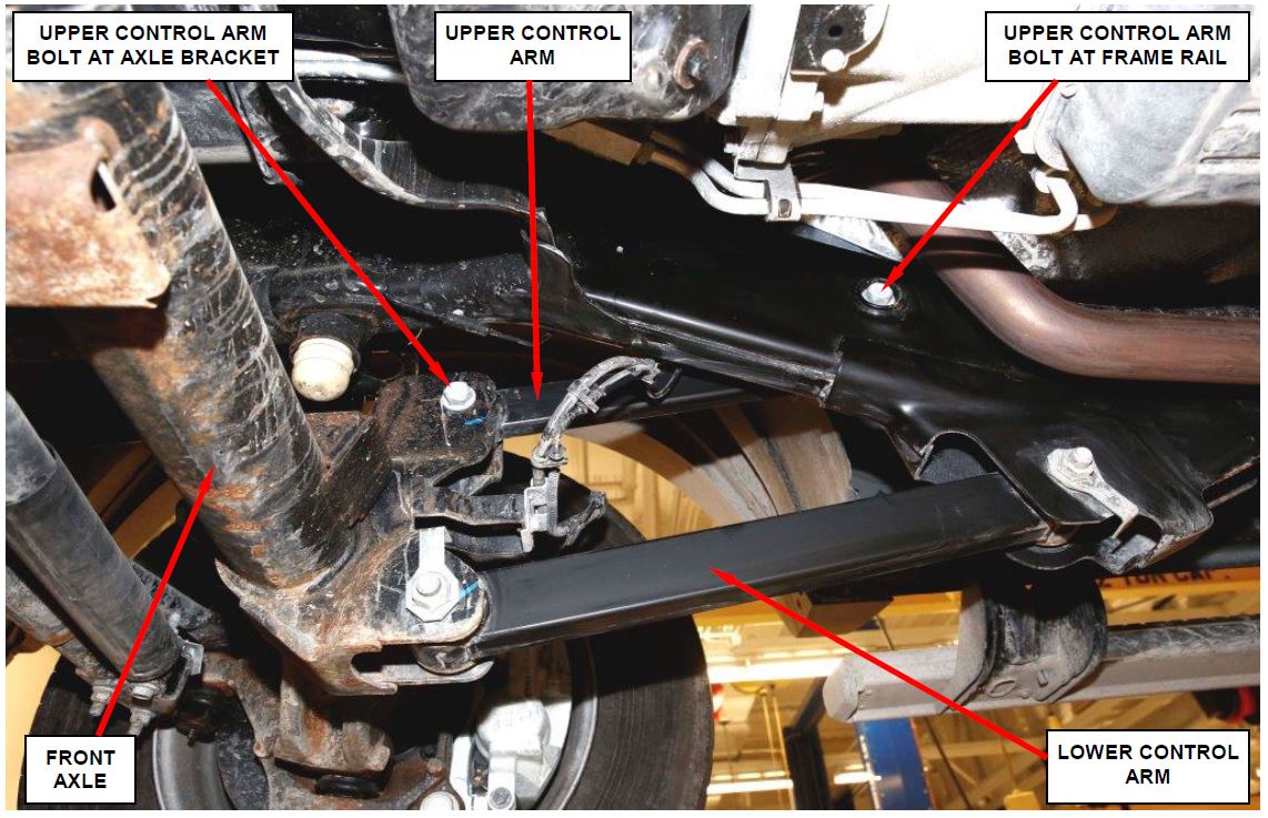
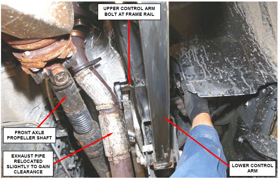
a. Remove and discard the upper control arm nut and bolt at the axle bracket (Figure 1).
b. Remove and discard the upper control arm nut and bolt at the frame rail (Figure 1).
Figure 1 – Front Suspension Upper Control Arm Bolts
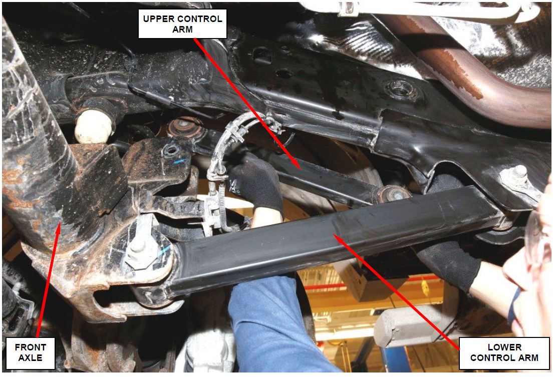
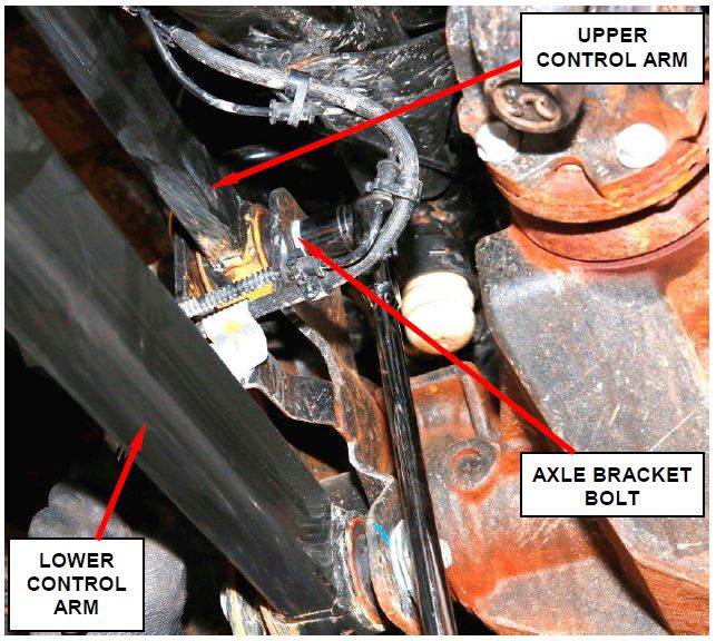
c. Remove the original upper control arm (Figure 2).
d. Position the new upper control arm at the axle bracket and frame rail.
e. Install the new upper control arm nut and bolt at the frame rail hand tight.
f. Install the new upper control arm nut and bolt at the axle bracket hand tight.
g. With full vehicle weight on the suspension, tighten the new upper control arm nut and bolt at the frame rail bracket to 185 ft. lbs. (250 N·m).
h. With full vehicle weight on the suspension, tighten the new upper control arm nut and bolt at the axle bracket to 185 ft. lbs. (250 N·m).
Figure 2 – Upper Control Arm Removal
- Use the following procedure to replace the left side front suspension upper control arm:
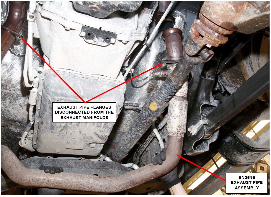
a. Disconnect the exhaust system at the engine exhaust manifolds (Figure 3).
b. Carefully reposition the exhaust system as required to gain access to the front suspension upper control arm bolt (Figure 3).
CAUTION: Use extreme care not to damage the oxygen sensor wires when relocating the exhaust pipe.
Figure 3 – Exhaust System
Figure 4 – Upper Control Arm Bolt at Frame Rail
c. Remove and discard the upper control arm nut and bolt at the axle bracket.
d. Remove and discard the upper control arm nut and bolt at the frame rail (Figure 4).
e. Remove the original upper control arm from the vehicle.
f. Position the new upper control arm at the axle bracket and frame rail.
g. Install the new upper control arm nut and bolt at the frame rail hand tight.
h. Install the new upper control arm nut and bolt at the axle bracket hand tight.
i. With full vehicle weight on the suspension, tighten the new upper control arm nut and bolt at the frame rail bracket to 185 ft. lbs. (250 N·m).
j. With full vehicle weight on the suspension, tighten the new upper control arm nut and bolt at the axle bracket to 185 ft. lbs. (250 N·m).
k. Reconnect the exhaust pipes at the engine exhaust manifolds. Tighten the exhaust manifold-to-exhaust pipe bolts to 24 ft. lbs. (18 N·m).
- If the vehicle had a broken upper control arm(s), continue with Section C. Front End Alignment and Steering Gear Poppet Valves Adjustment.
- If the vehicle did not have broken upper control arm(s), lower the vehicle from the hoist and return the vehicle to the customer.
NOTE: Front end alignment and poppet valves adjustment is only required on vehicles that came in with a broken front suspension upper control arm(s).
B. Front Suspension Upper Control Arms (equipped with diesel engine)
CAUTION: Only replace one upper control arm at a time to maintain front end alignment.
- Raise and support the vehicle on an appropriate drive-on hoist.
CAUTION: New nuts and bolts must be used when replacing the front suspension upper control arms. Discard the original nuts and bolts.
- Use the following procedure to replace the left side front suspension upper control arm:
a. Remove and discard the upper control arm nut and bolt at the axle bracket (Figure 5).
b. Remove and discard the nut and bolt at the frame rail and remove the original upper control arm.
c. Position the new upper control arm at the axle bracket and frame rail.
d. Install the new upper control arm bolts and finger-tighten the new upper control arm nuts.
e. With full vehicle weight on the suspension, tighten the right and left side nuts at the axle bracket and frame bracket to 185 ft. lbs. (250 N·m).
Figure 5 – Axle Bracket Bolt
- Use the following procedure to replace the right side front suspension upper control arm:
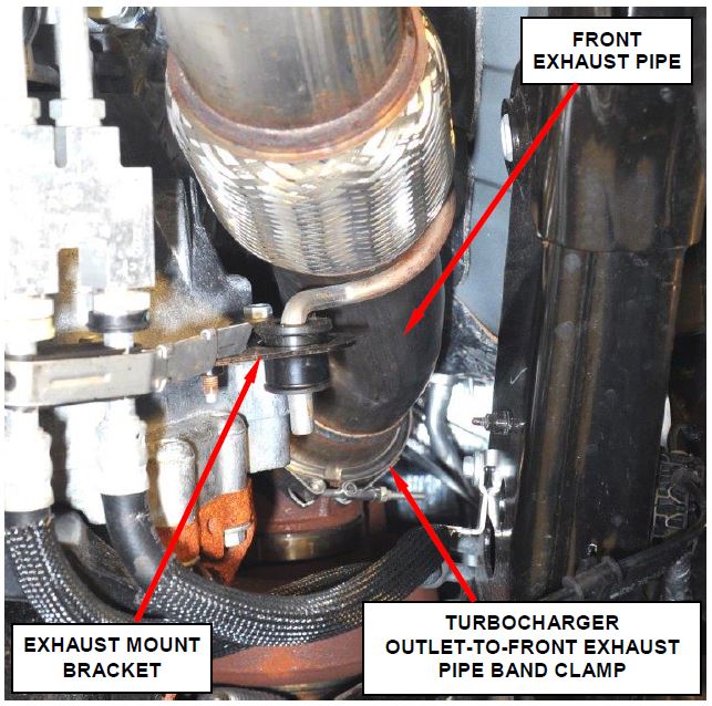
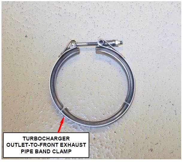
a. Disconnect the turbocharger outlet-to-front exhaust pipe band clamp (Figure 6).
b. Disconnect the transmission oil cooler tube bracket from the exhaust mount bracket.
Figure 6 – Turbocharger Outlet-to-Front Exhaust Pipe Band Clamp
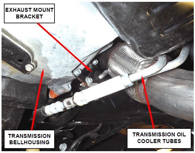
c. Disconnect the exhaust mount bracket at the transmission bellhousing (Figure 7).
Figure 7 – Exhaust Mount Bracket
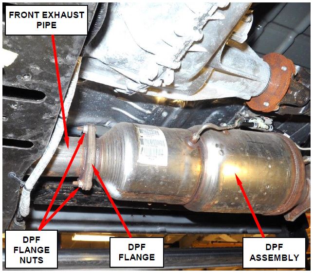
d. Remove and save the three front exhaust pipe-to-Diesel Particulate Filter (DPF) flange nuts (Figure 8).
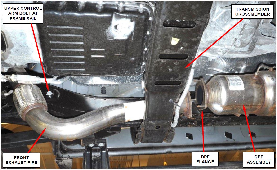
e. Carefully lower the front exhaust pipe to gain access to the upper control arm bolt at the frame rail (Figure 9).
NOTE: Do not completely remove the front exhaust pipe from the vehicle.
f. Remove and discard the upper control arm nut and bolt at the frame rail (Figure 9).
Figure 8 – Front Exhaust Pipe-to-DPF Flange Nuts
Figure 9 – Lower Front Exhaust Pipe to Gain Access to Upper Control Arm Bolt
g. Remove and discard the upper control arm nut and bolt at the axle bracket.
h. Remove the original upper control arm from the vehicle.
i. Position the new upper control arm at the axle bracket and frame
Figure 10 – Turbocharger Outlet-to-Front Exhaust Pipe Band Clamp
j. Install the new bolts, then finger tighten the new nuts.
k. With full vehicle weight on the suspension, tighten the upper control arm nuts at the axle bracket and frame bracket to 185 ft. lbs. (250 N·m).
l. Remove and discard the original turbocharger outlet-to-front exhaust pipe band clamp (Figure 10).
m. Install the new turbocharger outlet-to-front exhaust pipe band clamp into position (Figure 10).
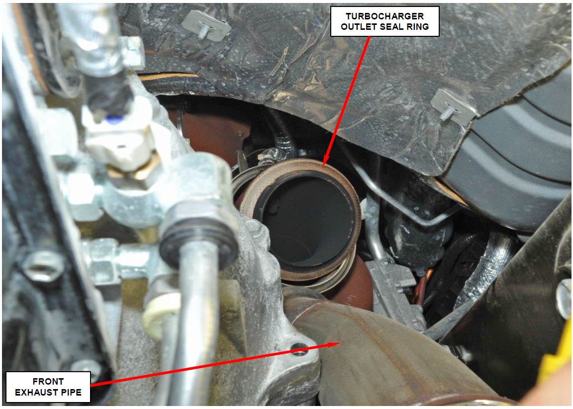
Figure 11 – Turbocharger Outlet Seal Ring
n. Remove and discard the original turbocharger outlet seal ring (Figure 11).
o. Install a new turbocharger outlet seal ring (Figure 11).
p. Remove and discard the original front exhaust pipe-to-DPF gasket.
q. Clean the front exhaust pipe-to-DPF flanges and install the new gasket.
r. Place the front exhaust pipe into position.
s. Connect the rubber exhaust mount bracket at the transmission bellhousing hand
t. Install the turbocharger outlet-to-front exhaust pipe band clamp hand ight.
u. Install the three front exhaust pipe-to-Diesel Particulate Filter (DPF) flange nuts. Tighten the three nuts to 44 ft. (60 N·m).
v. Tighten the exhaust mount bracket mounting bolts to 32 ft. lbs. (44 N·m).
w. Tighten the turbocharger outlet-to-front exhaust pipe band clamp to 13 ft. lbs. (18 N·m).
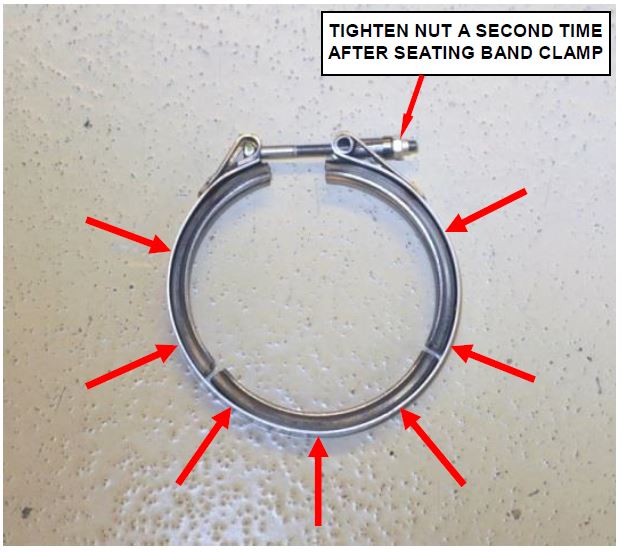
x. Using a small hammer, lightly tap around the outside diameter of the turbocharger outlet-to-front exhaust pipe band clamp to seat the clamp (Figure 12).
Figure 12 – Tap Around the Clamp with a Hammer to Seat Band Clamp
y. Tighten the turbocharger outlet-to-front exhaust pipe band clamp again to 13 ft. lbs. (18 N·m).
CAUTION: Failure to seat the band clamp and tightening the nut a second time could result in an exhaust leak.
- If the vehicle had a broken upper control arm(s), continue with Section C. Front End Alignment and Steering Gear Poppet Valves Adjustment.
- If the vehicle did not have broken upper control arm(s), lower the vehicle from the hoist and return the vehicle to the
NOTE: Front end alignment and poppet valves adjustment is only required on vehicles that came in with a broken front suspension upper control arm(s).
C. Front End Alignment and Steering Gear Poppet Valves Adjustment
- Place the vehicle on an appropriate alignment rack.
- Install wheel alignment equipment following the alignment machine instructions.
- Use the following alignment specifications:
4500/5500 SERIES – WHEEL BASE 144.5, 164.4, 168.5, 173.4
| FRONT ALIGNMENT | PREFERRED SETTING | ACCEPTABLE RANGE |
| CAMBER – LEFT | 0.10° | -0.40° to +0.60° |
| CAMBER – RIGHT | 0.10° | -0.40° to +0.60° |
| CROSS-CAMBER | 0.00° | -0.50° to +0.50° |
| CASTER – LEFT | +7.80° | +7.30° to +8.30° |
| CASTER – RIGHT | +8.10° | +7.60° to +8.60° |
| CROSS-CASTER | 0.30° | +0.20° to 0.80° |
| TOE – TOTAL* | +0.20° | +0.10° to +0.30° |
| Positive toe (+) is toe-in and negative toe (−) is Toe-out. | ||
| * TOTAL TOE is the sum of both the left and right wheel toe settings. TOTAL TOE should be equally split between each wheel on the same axle to ensure the steering wheel is centered after setting toe. | ||
| REAR ALIGNMENT | PREFERRED SETTING | ACCEPTABLE RANGE |
| CAMBER | -0.10° | -0.45° to +0.25° |
| CROSS-CAMBER | 0.00° | -0.30° to +0.30° |
| TOE – TOTAL* | +0.10° | -0.20° to +0.40° |
| THRUST ANGLE | 0.00° | -0.40° to +0.40° |
| Positive toe (+) is toe-in and negative toe (−) is Toe-out. | ||
| * TOTAL TOE is the sum of both the left and right wheel toe settings. TOTAL TOE should be equally split between each wheel on the same axle to ensure the steering wheel is centered after setting toe. | ||
4500/5500 SERIES – WHEEL BASE 192.5, 197.4
| FRONT ALIGNMENT | PREFERRED SETTING | ACCEPTABLE RANGE |
| CAMBER – LEFT | 0.10° | -0.40° to +0.60° |
| CAMBER – RIGHT | 0.10° | -0.40° to +0.60° |
| CROSS-CAMBER | 0.00° | -0.50° to +0.50° |
| CASTER – LEFT | +8.30° | +7.80° to +8.80° |
| CASTER – RIGHT | +8.60° | +8.10° to +9.10° |
| CROSS-CASTER | 0.30° | +0.20° to -0.80° |
| TOE – TOTAL* | +0.20° | +0.10° to +0.30° |
| Positive toe (+) is toe-in and negative toe (−) is Toe-out. | ||
| * TOTAL TOE is the sum of both the left and right wheel toe settings. TOTAL TOE should be equally split between each wheel on the same axle to ensure the steering wheel is centered after setting toe. | ||
| REAR ALIGNMENT | PREFERRED SETTING | ACCEPTABLE RANGE |
| CAMBER | -0.10° | -0.45° to +0.25° |
| CROSS-CAMBER | 0.00° | -0.30° to +0.30° |
| TOE – TOTAL* | +0.10° | -0.20° to +0.40° |
| THRUST ANGLE | 0.00° | -0.40° to +0.40° |
| Positive toe (+) is toe-in and negative toe (−) is Toe-out. | ||
| * TOTAL TOE is the sum of both the left and right wheel toe settings. TOTAL TOE should be equally split between each wheel on the same axle to ensure the steering wheel is centered after setting toe. | ||
4500/5500 SERIES – WHEEL BASE 204.5
| FRONT ALIGNMENT | PREFERRED SETTING | ACCEPTABLE RANGE |
| CAMBER – LEFT | 0.10° | -0.40° to +0.60° |
| CAMBER – RIGHT | 0.10° | -0.40° to +0.60° |
| CROSS-CAMBER | 0.00° | -0.50° to +0.50° |
| CASTER – LEFT | +8.60° | +7.60° to +9.60° |
| CASTER – RIGHT | +8.90° | +7.90° to +9.90° |
| CROSS-CASTER | 0.30° | -0.20° to +0.80° |
| TOE – TOTAL* | +0.20° | +0.10° to +0.30° |
| Positive toe (+) is toe-in and negative toe (−) is Toe-out. | ||
| * TOTAL TOE is the sum of both the left and right wheel toe settings. TOTAL TOE should be equally split between each wheel on the same axle to ensure the steering wheel is centered after setting toe. | ||
| REAR ALIGNMENT | PREFERRED SETTING | ACCEPTABLE RANGE |
| CAMBER | -0.10° | -0.45° to +0.25° |
| CROSS-CAMBER | 0.00° | -0.30° to +0.30° |
| TOE – TOTAL* | +0.10° | -0.20° to +0.40° |
| THRUST ANGLE | 0.00° | -0.40° to +0.40° |
| Positive toe (+) is toe-in and negative toe (−) is Toe-out. | ||
| * TOTAL TOE is the sum of both the left and right wheel toe settings. TOTAL TOE should be equally split between each wheel on the same axle to ensure the steering wheel is centered after setting toe. | ||
- Use the following procedure to adjust the steering gear central poppet valve:
a. Place the front wheels in the straight ahead position.
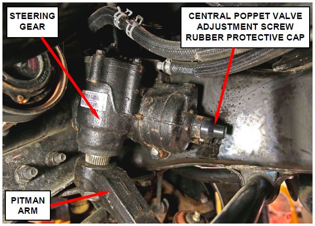
b. Remove and save the central poppet valve adjustment screw rubber protective cap (Figure 13).
Figure 13 – Central Poppet Adjustment Screw Rubber Protective Cap
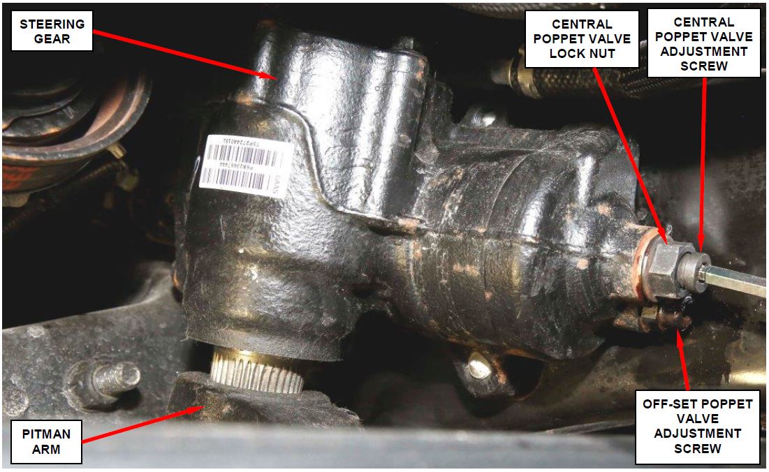
Figure 14 – Central Poppet Valve Lock Nut and Adjustment Screw
c. Loosen the central poppet valve adjustment screw lock nut (Figure 14).
d. While holding the lock nut, tighten the central poppet adjustment screw until it bottoms out in the steering gear (Figure 14). This will bottom the internal central poppet valve.
NOTE: With the central poppet valve bottomed in the steering gear, when the steering is cycled, the central poppet valve self-adjusts to the proper position. In essence, the central poppet valve adjuster screw is only being used as a tool to bottom the central poppet valve.
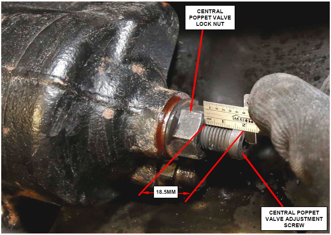
Figure 15 – Adjust and Lock Down the Central Poppet Valve
e. While holding the central poppet valve adjustment screw lock nut, back off the central poppet adjustment screw until 18.5 mm of the screw is protruding from the lock nut (Figure 15).
f. Tighten the central poppet valve adjustment screw lock nut to 90 ft. lbs. (120 N·m) (Figure 15).
g. With the front wheels on the alignment rack turn-tables, start the engine and turn the steering wheel to the full right turn position (steering against the right steering stop).
h. Return the front wheels to the straight ahead position and then turn off the engine.
- Use the following procedure to adjust the steering gear off-center poppet valve:
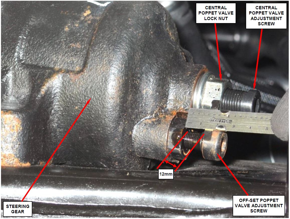
a. Loosen the off-center poppet valve adjustment screw until 12 mm of the screw is exposed (Figure 16).
NOTE: When loosening the off-center poppet valve adjustment screw, at about 1.5 mm, an increase in turning effort will be experienced. This increased drag is the off-center poppet valve adjusting screw being pulled out of the internal valve. The valve will be pushed back to the correct depth on the adjusting screw when the steering is cycled from lock-to-lock.
b. Tighten the off-center poppet valve adjustment screw to 48 ft. lbs. (65 N·m) (Figure 16).
Figure 16 – Steering Gear Off-Center Poppet Valve Adjustment
- Install the central poppet valve adjustment screw rubber protective cap (Figure 13).
- With the front wheels on the alignment rack turn-tables, start the engine and cycle the steering wheel lock-to-lock twice and then return to the straight ahead position.
NOTE: This will position the steering gear valves in the steering gear.
- Remove the alignment equipment from the vehicle.
- Check the power steering fluid level and adjust as required.
- Road test the vehicle to ensure that the steering wheel is straight and the vehicle steers properly.
- Return the vehicle to the customer.
Completion Reporting and Reimbursement
Claims for vehicles that have been serviced must be submitted on the DealerCONNECT Claim Entry Screen located on the Service tab. Claims submitted will be used by FCA to record recall service completions and provide dealer payments.
Use the following labor operation number and time allowance:
| Labor Operation Number | Time Allowance | |
|---|---|---|
| Replace right and left side front suspension upper control arms (equipped with gas engine) | 02-R3-41-82 | 0.7 hours |
| Replace right and left side front suspension upper control arms (equipped with diesel engine) | 02-R3-41-83 | 1.0 hours |
| Related Operation | ||
| Front end alignment and steering gear poppet valve adjustment (only for trucks that came in with a broken upper control arm(s)) | 02-R3-41-50 | 1.5 hours |
Add the cost of the recall parts package plus applicable dealer allowance to your claim.
NOTE: See the Warranty Administration Manual, Recall Claim Processing Section, for complete recall claim processing instructions.
Dealer Notification
To view this notification on DealerCONNECT, select “Global Recall System” on the Service tab, then click on the description of this notification.
Owner Notification and Service Scheduling
All involved vehicle owners known to FCA are being notified of the service requirement by first class mail. They are requested to schedule appointments for this service with their dealers. A generic copy of the owner letter is attached.
Enclosed with each owner letter is an Owner Notification postcard to allow owners to update our records if applicable.
Vehicle Lists, Global Recall System, VIP and Dealer Follow Up
All involved vehicles have been entered into the DealerCONNECT Global Recall System (GRS) and Vehicle Information Plus (VIP) for dealer inquiry as needed.
GRS provides involved dealers with an updated VIN list of their incomplete vehicles. The owner’s name, address and phone number are listed if known. Completed vehicles are removed from GRS within several days of repair claim submission.
To use this system, click on the “Service” tab and then click on “Global Recall System.” Your dealer’s VIN list for each recall displayed can be sorted by: those vehicles that were unsold at recall launch, those with a phone number, city, zip code, or VIN sequence.
Dealers must perform this repair on all unsold vehicles before retail delivery. Dealers should also use the VIN list to follow up with all owners to schedule appointments for this repair.
Recall VIN lists may contain confidential, restricted owner name and address information that was obtained from the Department of Motor Vehicles of various states. Use of this information is permitted for this recall only and is strictly prohibited from all other use.
Additional Information
If you have any questions or need assistance in completing this action, please contact your Service and Parts District Manager.
Customer Services / Field Operations
FCA US LLC
FRONT SUSPENSION UPPER
CONTROL ARMS
IMPORTANT SAFETY RECALL
R34/NHTSA15V-468
This notice applies to your vehicle (VIN: xxxxxxxxxxxxxxxxx).
This notice is sent to you in accordance with the National Traffic and Motor Vehicle Safety Act. Dear: (Name)
FCA has decided that a defect, which relates to motor vehicle safety, exists in certain 2015 model year 4500 and 5500 series RAM trucks .
.
| The problem is… | The front suspension upper control arms on your truck may have been improperly welded during the manufacturing process. The weld connecting the bushing loop to the upper control arm could break under certain driving conditions. A broken upper control arm could cause a loss of vehicle stability and/or a crash without warning. |
| What your dealer will do… | FCA will repair your vehicle free of charge. To do this, your dealer will replace the right and left upper control arms. The work will take about 3 hours to complete. However, additional time may be necessary depending on service schedules. |
| What you must do to ensure your safety… | Simply contact your Chrysler , Jeep , Jeep , Dodge , Dodge or RAM or RAM dealer right away to schedule a service appointment. Ask the dealer to hold the parts for your vehicle or to order them before your appointment. Please bring this letter with you to your dealer. dealer right away to schedule a service appointment. Ask the dealer to hold the parts for your vehicle or to order them before your appointment. Please bring this letter with you to your dealer. |
| If you need help… | If you have questions or concerns which your dealer is unable to resolve, please contact the FCA Group Recall Assistance Center at either recalls.mopar.com or 1-800-853-1403. |
Please help us update our records by filling out the attached prepaid postcard if any of the conditions listed on the card apply to you or your vehicle. If you have further questions go to recalls.mopar.com.
If you have already experienced this specific condition and have paid to have it repaired, you may visit www.fcarecallreimbursement.com to submit your reimbursement request online or you can mail your original receipts and proof of payment to the following address for reimbursement consideration: FCA Customer Assistance, P.O. Box 21-8004, Auburn Hills, MI 48321-8007, Attention: Recall Reimbursement. Once we receive and verify the required documents, reimbursement will be sent to you within 60 days. If you’ve had previous repairs and/or reimbursement you may still need to have the recall repair performed on your vehicle.
If your dealer fails or is unable to remedy this defect without charge and within a reasonable time, you may submit a written complaint to the Administrator, National Highway Traffic Safety Administration, 1200 New Jersey Ave., S.E., Washington, DC 20590, or you can call the toll-free Vehicle Safety Hotline at 1-888-327-4236 (TTY 1-800-424-9153), or go to safercar.gov.
We’re sorry for any inconvenience, but we are sincerely concerned about your safety. Thank you for your attention to this important matter.
Customer Services / Field Operations
FCA US LLC
Note to lessors receiving this recall: Federal regulation requires that you forward this recall notice to the lessee within 10 days.
Safety Recall R34 / NHTSA 15V-468
Front Suspension Upper Control Arms
September 2015
 Loading...
Owner Notification Letter
 Loading...
Safety Recall R34 / NHTSA 15V-468
Front Suspension Upper Control Arms
September 2015
 Loading...
Safety Recall Advanced Communication – R34
07/21/2015
 Loading...
Renotification Notice
August 23, 2016
 Loading...
Renotification Notice
March 30, 2016
 Loading...
Chronology
July 21, 2015
 Loading...
Other Recall Related Document
September 21, 2015
 Loading...
Recall Acknowledgement
August 19, 2015
 Loading...
- BUFF OUT IMPERFECTIONS: Meguiar's Ultimate Compound removes scratches, swirls & oxidation for a clear, perfect finish
- SHOWROOM SHINE: Advanced car compound removes scratches, swirls, oxidation & water spots and restores color & clarity for a showroom shine in minutes
- CLEAR COAT SAFE: Auto compound safely removes scratches and other defects without hazing on clear coats & all gloss paints. Easy DIY fix by hand or da polisher
- LIKE-NEW SHINE: Meguiar's exclusive micro-abrasive technology quickly removes scratches & restores clarity and shine for a stunning, swirl-free finish.
- FAST & FLAWLESS: Meguiar's Ultimate Compound cuts fast, removes scratches and swirls without hazing, leaving a pro-detailer finish.
- 3-IN-ONE CERAMIC TECHNOLOGY: One 16 fl oz bottle of Nu Finish Once a Year Polish and Sealant, a car polish and paint sealant with 3-in-1 Ceramic Technology to repair, seal and repel
- REPAIRS SCRATCHES AND RENEWS SHINE: Long-lasting auto polish that helps repair fine swirls, scuffs and scratches while renewing the shine on paint and chrome, leaving a glossy, wet finish without any wax
- PREVENTS FUTURE SCRATCHES: Innovative Ceramic Technology forms an effective, durable protective barrier that helps prevent future scratches from forming and delivers extreme water beading for easier maintenance
- NO RUBBING OR BUFFING: Unique liquid polish that requires no rubbing or buffing and can even be applied in direct sunlight, unlike conventional car wax
- THE ONCE A YEAR CAR POLISH AND SEALANT: With just one application, you can polish and protect your car’s paint for an entire year* (*Based on U.S. average automatic car washes per year)
- The polish gives deep reflections & a hi-gloss paint finish
- Eliminates fine swirl marks
- Conditioning oils add depth of colour and maximum gloss prior to waxing, especially on dark coloured cars
- Quickly and gently removes fine swirls and towel marks for mirror-like reflections
- Safe and on all glossy paints, including clear coats.Pre-waxing glaze that prepares the surface for wax while offering deep reflections and high gloss
- CLEANER WAX: One-step liquid wax cleans your paint while you wax
- HIGH GLOSS SHINE: Rich conditioning oils polish and protect, leaving finish with a high gloss shine
- SAFE ON ALL GLOSSY FINISHES: Safely and effectively cleans surface contaminants and blemishes from all glossy paint finishes including clear coats and single-stage paint
- EASE OF USE: Easier to use than traditional carnauba wax
- VERSATILE APPLICATION: Can be applied by hand or Dual Action Polisher like Meguiar's MT300
- EXCEPTIONAL RESULTS: Advanced technology formula provides a deep gloss and rich, swirl-free results, ensuring the luxury your vehicle deserves. This mirror glaze goes above and beyond to produce a high gloss finish with no defects left behind.
- NO MORE SWIRLS: Meguiar's M20508 Mirror Glaze Ultra Finishing Polish permanently and efficiently removes swirls and light defects from all paint in favor of a deep gloss. This powerful car polish gets the job done and leaves a lasting finish.
- STUNNING SHINE: Ultra Finishing Polish produces deep reflections and high gloss without leaving a mess behind. Treat your ride to a stunning shine with a professional polish that achieves an impeccable shine and gloss.
- EASY-TO-USE: Whether working by rotary, DA polisher, or hand, this professional polishing compound goes on and wipes off easily for a quick and easy cleanup. This Finishing Polish is the perfect way to enhance and refine paint and increase gloss.
- MULTIPLE WAYS TO APPLY: Formulated for use by hand, DA polisher, or rotary buffer. It's the perfect product to follow a more aggressive compound like Ultra Cut Compound M105 and before applying paint protection, like Pro Hybrid Ceramic Sealant M27.
- EASY SCRATCH and SWIRL REPAIR - If your car has light scratches, swirls, or other marks - you can easily fix that with our Scratch & Swirl Remover Kit! Using the included buffer pad, our specially formulated compound will allow you to easily remove and "erase" years of wear and tear from your vehicles paint and overall appearance!
- ULTIMATE PAINT REPAIR- Not only will this remove swirls and scratches, it will restore the gloss and shine of your paint and bring it back to its original brilliance! The special rubbing compound will remove water spots, oxidation and other contaminants from your paint!
- PREMIUM CHEMICALS - We formulate all our products to ensure they are the best! Professional grade, but easy enough for anyone to use! We use only the absolute best chemicals and ensure there are no unnecessary color dyes or scents!
- ADVANCED SOLUTION FOR ALL PAINT TYPES - Car paint scratch repair is safe to use on all paints and colors. You can safely use it on any clearcoat, single stage, or multi stage paint!
- REVOLUTIONARY PRODUCT - This scratch remover for vehicles provides an effortless and secure way to remove scratches.
- Advanced Formula 3-in-1. Our fortify quick coat is your all-in-one ceramic coating hydrophobic spray. Shine Armor Fortify Quick Coat ceramic car wax provides a waterless wash, coat, and shine, all-in-one convenient product.
- No Streaking, Smearing Or Scratching. Shine Armor Fortify Quick Coat premium formula ceramic car coating is a gentle and effective car polish for any vehicle! Get a clean, shiny finish without hurting your car's paint.
- Cuts Dirt, Grime & Grease. Our Quick Coat ceramic wax car sealant eliminates dirt, grime & grease instantly! Our signature 3-in-1 formula gives you a waterless car wash, coat and shine for a clean, showcase look.
- Safe For All Surfaces. Use this car wax spray-on automobiles, boats, motorbikes, RVs, four-wheelers and more! This spray wax is the perfect blend of surfactants and SiO2 ceramic-coating science.
- Superior Products. This means superior shine for your cars! Our ceramic quick coat also works as a sealer to give your vehicle a clear shield of protection while also providing a beautiful gloss. Which makes our ceramic spray the perfect Christmas Gift for the gearhead in your life!
- Can be applied to wet or dry paint
- Provides a deep, dark gloss and shine while adding protection
- Ease and convenience of a spray-on, wipe-off product saves on time
- Can be applied in full sun and won't whiten plastic trim
- Offers protection against the sun
- OUTSTANDING POLISH: Top-performing glaze among hand-applied polishes, glazes, waxes and sealants
- SHOW CAR SHINE: Restores a dazzling, deep wet shine
- SAFE FOR ALL FINISHES: Body shop safe and effective on all glossy paint finishes including clear coats
- DRIES CLEAR: Does not dry white, leaving a clear glossy shine
- CHOOSE HOW YOU USE: Formulated for use by hand, DA polisher or rotary buffer
- One 16 oz bottle of Nu Finish The Once A Year Car Polish
- Automotive polish that is made up of a series of zinc cross-linking polymer emulsions that help it last longer than any other polish on the market
- Nu Finish car polish can be applied anywhere, even in direct sunlight
- Also an ideal boat polish, motorcycle polish and chrome polish
- The only auto polish tough enough to be called "The Once A Year Car Polish”
Last update on 2025-05-08 / Affiliate links / Images from Amazon Product Advertising API
This product presentation was made with AAWP plugin.
