| “This site contains affiliate links for which OEMDTC may be compensated” |
June 27, 2019 NHTSA CAMPAIGN NUMBER: 19V498000
A fuel leak in the presence of an ignition source increases the risk of a fire.
NHTSA Campaign Number: 19V498
Manufacturer Chrysler (FCA US LLC)
Components FUEL SYSTEM, DIESEL
Potential Number of Units Affected 498
Summary
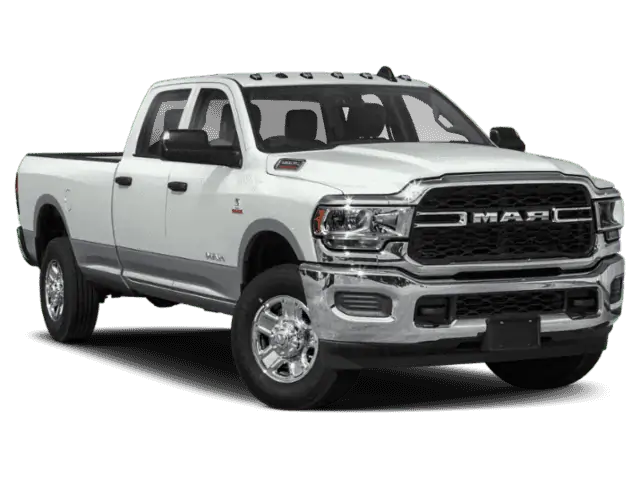
Chrysler (FCA US LLC) is recalling certain 2019 Ram
 2500 and 3500 trucks, and 3500, 4500, and 5500 Cab Chassis vehicles equipped with diesel engines. The fuel lines may leak fuel into the engine compartment.
Remedy
Chrysler will notify owners, and dealers will inspect the fuel lines, replacing them if necessary, free of charge. The recall began July 18, 2019. Owners may contact Chrysler
 customer service at 1-800-853-1403. Chrysler
 ’s number for this recall is V76.
Notes
Owners may also contact the National Highway Traffic Safety Administration Vehicle Safety Hotline at 1-888-327-4236 (TTY 1-800-424-9153), or go to www.safercar.gov.
Check if your Vehicle has a Recall
July 2019
Dealer Service Instructions for:
Safety Recall V76 / NHTSA 19V-498 Fuel Injector Lines
Remedy Available
| 2019 | (DJ) | RAM 2500 Pickup 2500 Pickup |
| 2019 | (D2) | RAM 3500 Pickup 3500 Pickup |
| 2019 | (DD) | RAM 3500 Cab Chassis 3500 Cab Chassis |
| 2019 | (DP) | RAM 4500/5500 Cab Chassis 4500/5500 Cab Chassis |
NOTE: This recall applies only to the above trucks equipped with a 6.7L Cummins diesel engine (Sales Code ETL or ETN or ETM).
NOTE: Some vehicles above may have been identified as not involved in this recall and therefore have been excluded from this recall.
IMPORTANT: Some of the involved vehicles may be in dealer new vehicle inventory. Federal law requires you to complete this recall service on these vehicles before retail delivery. Dealers should also consider this requirement to apply to used vehicle inventory and should perform this recall on vehicles in for service. Involved vehicles can be determined by using the VIP inquiry process.
Subject
The diesel engine on about 560 of the above vehicles may have been manufactured with fuel lines with incorrectly formed end fittings that may not properly seal to other fuel system components. Fuel lines that do not properly seal may lead to a fuel leak in the engine compartment. A fuel leak in the engine compartment may lead to a vehicle fire, which may increase risk of injury to occupants and persons outside the vehicle, as well as property damage.
Repair
Cummins will send a representative to inspect the fuel line date codes. If any of the fuel line date codes are found to be within the suspect build population, the suspect line(s) will be replaced.
Alternate Transportation
Dealers should attempt to minimize customer inconvenience by placing the owner in a loaner vehicle if inspection determines that fuel tube replacement is required and the vehicle must be held overnight.
Parts Information
Do NOT place an order, parts will be manually allocated by MOPAR.
Parts Return
No parts return required for this campaign.
Special Tools
The following special tools are required to perform this repair:
| ➢ NPN | wiTECH micro pod II |
| ➢ NPN | Laptop Computer |
| ➢ NPN | wiTECH Software |
Service Procedure
Do NOT perform any of these service procedures without prior authorization. A Cummins representative will be dispatched to your dealership to inspect the fuel tube date codes. If any of the fuel tube date codes are found to be within the suspect build population, the Cummins representative will identify which suspect tubes(s) must be replaced. Replacement of any fuel tube without prior authorization will result in forfeit of warranty reimbursement.
A. Tube Removal Preparation Procedures
CAUTION: Cleanliness cannot be over emphasized when handling or replacing diesel fuel system components. This especially includes the fuel injectors, high-pressure fuel tubes and fuel injection pump. Very tight tolerances are used with these parts. Dirt contamination could cause rapid part wear and possible plugging of fuel injector nozzle tip holes. This in turn could lead to possible engine misfire. Always wash/clean any fuel system component thoroughly before disassembly and then air dry. Cap or cover any open part after disassembly. Before assembly, examine each part for dirt, grease or other contaminants and clean if necessary.
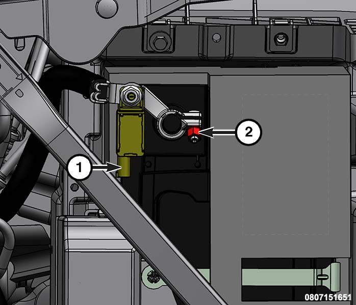
- Disconnect the Intelligent Battery Sensor (IBS) wire harness connector (1) (Figure 1).
NOTE: Failure to disconnect the IBS wire harness connector can lead to damage of the IBS wire harness connector.
- Loosen the ground terminal nut (2) and remove the negative battery cable with IBS from the battery and isolate it (Figure 1).
Figure 1 – Primary Battery
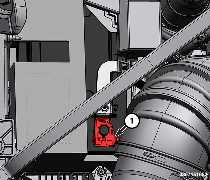
NOTE: If the vehicle is equipped with an auxiliary battery, when disconnecting and isolating the negative battery cable for the 12volt system, both batteries will need to be disconnected to power down the vehicle.
- If the vehicle is equipped with an auxiliary battery, Loosen the clamp (1) and remove the clamp from the battery and isolate (Figure 2).
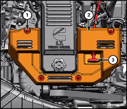
- Remove the oil dip stick (3) (Figure 3).
- Remove the bolts (1) and the engine cover (2) (Figure 3).
Figure 2 – Auxiliary Battery
Figure 3 – Engine Cover
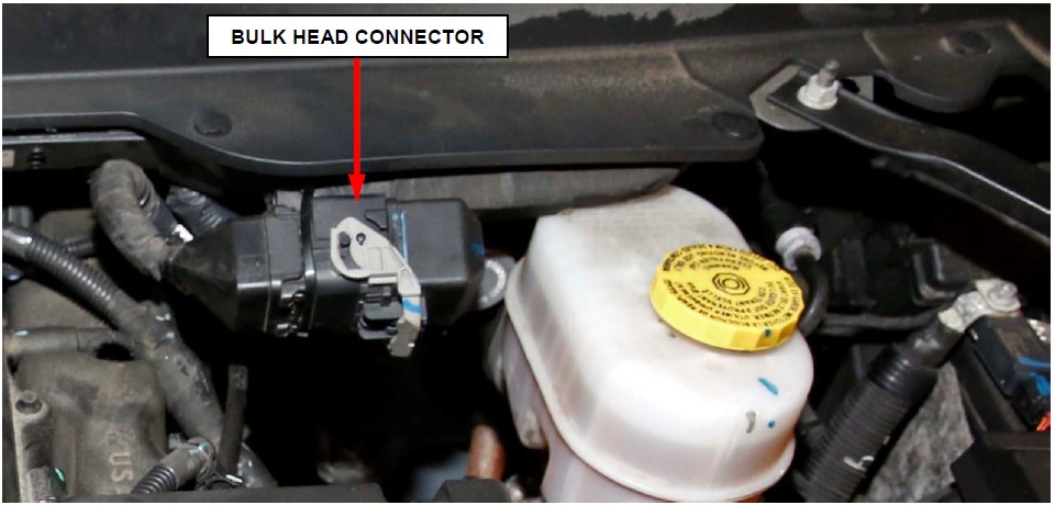
- Cut the cable tie and position aside the bulk head connector (Figure 4).
Figure 4 – Bulk Head Connector
- Replace only the fuel tubes identified by the Cummins representative which require replacement. Follow the appropriate service procedure depending on which tube(s) must be replaced:
- Section Tube Replacement – Fuel Injection Pump to Fuel Rail
- Section Tube Replacement – Fuel Rail to Fuel Injector
B. Tube Replacement – Fuel Injection Pump to Fuel Rail
NOTE: The short upper pump to fuel rail tube may be removed separately without disconnecting the long lower pump to fuel rail tube. However, the long lower pump to fuel rail tube also requires removal of the short upper pump to fuel rail tube.
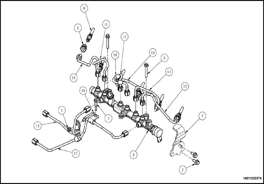
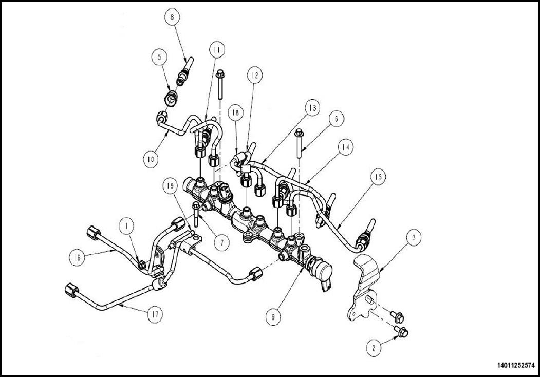
- Remove the nut (1) securing the high pressure pump to rail tubes (16 and 17) (Figure 5).
- Only if removing the long lower pump to fuel rail tube: Remove the bolt (7) securing the high pressure pump to rail tube (17) (Figure 5).
Figure 5 – Fuel Tubes
- Place a clean shop towels around fuel tubes being disconnected. If possible, do not allow fuel to drip down side of engine.
NOTE: If only replacing the short upper pump to fuel rail tube, it is not necessary to loosen the long lower pump to fuel rail tube. If replacing the long lower pump to fuel rail tube, both short upper and long lower pump to fuel rail tubes must be removed.
- Loosen the union nuts and carefully remove the fuel tube(s) (16 and 17) from the engine. Note position of tube(s) while removing (Figure 5).
NOTE: Use care not to bend fuel tubes when removing or installing.
- Carefully install the fuel tube(s) (16 and 17) to the engine. Tighten the high-pressure fuel injection pump-to-fuel rail fuel tube(s) at the pump first and then at the rail. Tighten the union nuts to 40 N·m (30 ft. lbs.) (Figure 5).
- Remove the shop towels from around fuel tubes that were disconnected.
- If previously removed: Install the bolt (7) securing the high pressure pump to rail tube (17). Tighten the bolt to 24 N·m (18 ft. lbs.) (Figure 5).
- Install the nut (1) securing the high pressure pump to rail tubes (16 and 17). Tighten the nut to 20 N·m (15 ft. lbs.) (Figure 5).
- Proceed to Section Reassembly and Fuel System Priming Procedures.
C. Tube Replacement – Fuel Rail to Fuel Injector
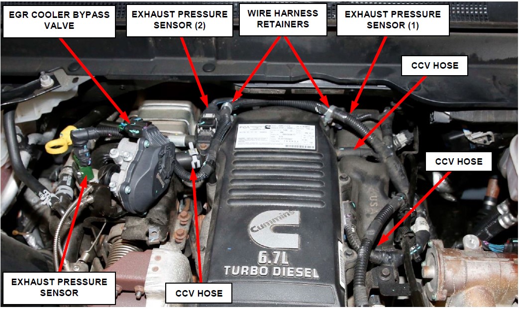
- Disconnect the exhaust pressure sensor wire harness connector (Figure 6).
- Disconnect the EGR cooler bypass valve wire harness connector (Figure 6).
- Disconnect the crankcase pressure sensor 2 wire harness connector (Figure 6).
- Release the wire harness retainers (Figure 6).
- Disconnect crankcase pressure sensor 1 wire harness connector (Figure 6).
- Disconnect the three Crank Case Ventilation (CCV) hoses from the crank case breather cover and cylinder head cover (Figure 6).
Figure 6 – Electrical Connectors and CCV Hoses
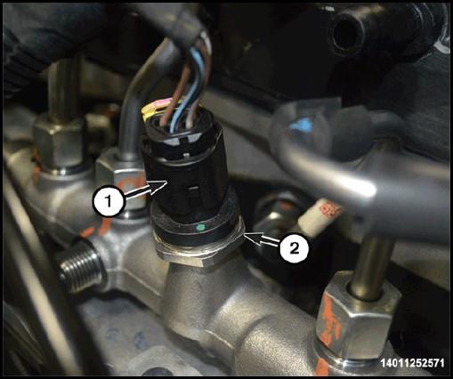
- Disconnect the fuel pressure sensor wire harness connector (1) (Figure 7).
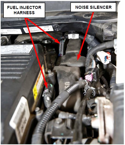
- Disconnect both fuel injector harness connectors (Figure 8).
- Position the engine harness to the side to allow clear access to the fuel rail noise silencer.
- Remove the fuel rail noise silencer (Figure 8).
- Thoroughly clean any dirt from fuel tubes and fuel tube nuts to minimize exposure to dirt/debris.
Figure 7 – Fuel Pressure Sensor
Figure 8 – Fuel Injector Harness and Nose Silencer
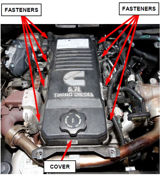
- Remove eight fasteners and the crank case breather cover (Figure 9).
Figure 9 – Crank Case Breather Cover
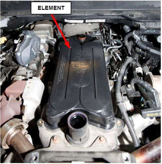
- Remove the crank case breather element (Figure 10).
Figure 10 – Crank Case Breather Element
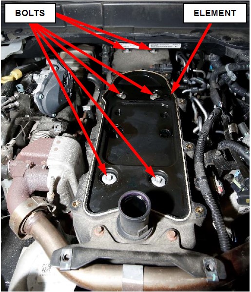
- Remove six bolts and remove the cylinder head cover (Figure 11).
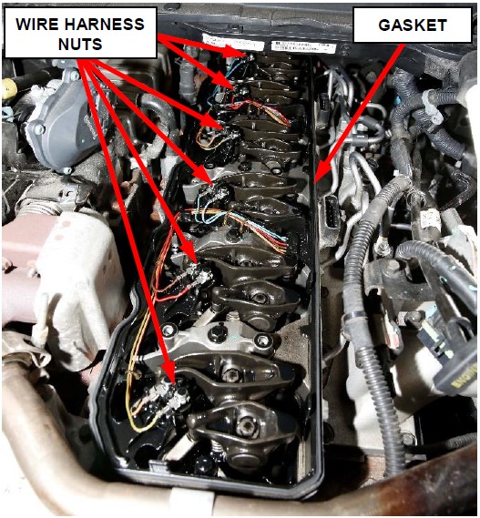
- Loosen the fuel injector wire harness nuts on the cylinder head cover gasket. Remove the cylinder head cover gasket (Figure 12).
Figure 11 – Cylinder Head Cover
Figure 12 – Cylinder Head Cover Gasket
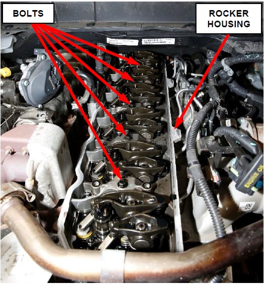
- Remove the bolts and the rocker housing (Figure 13).
- Place clean shop towels around any fuel tube fittings that will be disconnected. If possible, do not allow fuel to drip down side of engine.
NOTE: Rail-to-cylinder head fuel tubes are marked on the cylinder head side nut with cylinder number identification.
NOTE: Cylinder No. 3 fuel tube (12) is equipped with two vibration isolators (18). Do not remove or change the position of vibration isolators (18) (Figure 14).
Figure 13 – Rocker Housing
CAUTION: When loosening high-pressure tube fittings attached to a separate fitting (5), use a back-up wrench on fitting (5). Do not allow fittings (5) to rotate. Damage to both fuel tube and fitting will result (Figure 14).
NOTE: Use care not to bend fuel tubes when removing or installing.
CAUTION: Anytime a high-pressure fuel tube is removed from the engine, its fuel connector retaining nut (5) at the cylinder head must first be retorqued to prevent a leak between the high pressure connector and fuel injector inside the cylinder head (Figure 14).
CAUTION: When tightening high-pressure tube fittings attached to a separate fitting (5), use a back-up wrench on fitting (5). Do not allow fittings (5) to rotate. Damage to both fuel tube and fitting will result (Figure 14).
Figure 14 – Fuel Tubes
- Install the new fuel tube to the injector and fuel rail. Tighten the fittings hand tight at both ends of tube (Figure 14).
- Tighten fuel tube nut at the cylinder head to 55 N·m (41 ft. lbs.) (Figure 14).
- Tighten fuel tube nuts at the fuel rail to 45 N·m (33 ft. lbs.) (Figure 14).
NOTE: Ensure proper clearance between each fuel tube after torqueing both the fuel tube nut at the cylinder head and the fuel rail. The fuel tubes should have minimum clearance of 1.25mm between one another.
- Remove the shop towels around any fuel tube that was replaced.
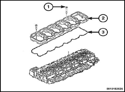
- Clean all the gasket sealing surfaces and inspect the rocker housing gasket (3) for damage and replace if necessary (Figure 15).
NOTE: If the rocker housing gasket (3) has been removed from the groove in the rocker housing (2), a NEW gasket must be installed (Figure 15).
Figure 15 – Rocker Housing Gasket
CAUTION: When installing rocker housing onto cylinder head, do not slide housing from side to side, the gasket could fall out or be damaged.
- Install the rocker housing and tighten the bolts finger tight. Working from center out, tighten bolts to 24 N·m (18 ft. lbs.) (Figure 13).
- Inspect the cylinder head cover gasket for tears, or splits. Replace if necessary (Figure 12).
- Install the cylinder head cover gasket on the rocker housing. Tighten the fuel injector wire harness nuts to 1.5 N·m (13 in. lbs.) (Figure 12).
- Install the cylinder head cover then install the six bolts fastening the cover. Tighten the bolts to 24 N·m (18 ft. lbs.) (Figure 11).
- Install the crank case breather element (Figure 10).
- Install the crank case breather cover and the eight fasteners securing the cover. Tighten the fasteners to 10 N·m (89 in. lbs.) (Figure 9).
- Install the fuel rail noise silencer (Figure 8).
- Connect both fuel injector harness connectors (Figure 8).
- Connect the fuel pressure sensor wire harness connector (1) (Figure 7).
- Connect the three CCV hoses to the cylinder head cover and crank case breather cover (Figure 6).
- Connect crankcase pressure sensor 1 wire harness connector (Figure 6).
- Attach the wire harness retainers (Figure 6).
- Connect the crankcase pressure sensor 2 wire harness connector (Figure 6).
- Connect the EGR cooler bypass valve wire harness connector (Figure 6).
- Connect the exhaust pressure sensor wire harness connector (Figure 6).
- Proceed to Section Reassembly and Fuel System Priming Procedures.
D. Reassembly and Fuel System Priming Procedures.
- Attach the bulk head connector (Figure 4).
- Install the engine cover (2) and the bolts (1) securing the cover. Tighten the bolts to 10 N·m (89 in. lbs.) (Figure 3).
- Install the oil dip stick (3) (Figure 3).
- If the vehicle is equipped with an auxiliary battery, install the clamp (1) to the negative post and tighten to 6 N·m (53 in. lbs.) (Figure 2).
- Install the negative battery cable with IBS to the negative post and tighten to 6 N·m (53 in. lbs.) (Figure 1).
- Connect the IBS wire harness connector (Figure 1).
- Be sure there is fuel in the fuel tank.
- Turn ignition switch to the RUN position. This will operate fuel transfer pump for a minimum of 30 seconds.
- Turn the ignition switch to the OFF position, and leave it off for at least 5 seconds.
NOTE: A certain amount of air becomes trapped in the fuel system when fuel system components on the supply and/or high-pressure side are serviced or replaced. Fuel system priming is accomplished using the electric fuel transfer (lift) pump.
The fuel transfer (lift) pump is self-priming: When the ignition switch is turned to the run position (without cranking engine), the pump operates for a minimum of 30 second. In cold temperatures, the lift pump operates for up to 35 seconds. Two priming cycles (each with a duration of 30 seconds) must be performed any time the fuel system is serviced
- Turn the ignition switch to the RUN position. This will complete an additional priming cycle and operate the fuel transfer pump for a minimum of 30 seconds.
- Start the engine. If the engine does not start after 25 seconds, turn the ignition switch to the OFF position, and leave it off for at least 5 seconds. Repeat the previous step until the engine starts. When engine does start, allow the engine to idle for a minimum of 30 seconds. The engine may run erratically and be noisy for a few minutes. This is a normal condition.
- Fuel system priming is now completed.
CAUTION: Do not engage the starter motor for more than 30 seconds at a time. Allow two minutes between cranking intervals.
WARNING: The fuel injection pump supplies extremely high fuel pressure to each individual injector through the high-pressure tubes. Fuel under this amount of pressure can penetrate the skin and cause personal injury. Wear safety goggles and adequate protective clothing. Do not loosen fuel fittings while engine is running.
WARNING: Engine may start while cranking starter motor
- Start engine and check for leaks.
- Validation Run Fuel System Leak Test for Diesel ECM Controller Modules (Fuel Pressure Override Test)
- Install a battery charger and verify that the charging rate provides 13.2 to 13.5 volts. Do not allow the charger to time out during the flash process. Set the battery charger timer (if so equipped) to continuous charge.
NOTE: Use an accurate stand-alone voltmeter. The battery charger volt meter may not be sufficiently accurate. If voltage reading is too high, apply an electrical load by activating the park or headlamps and/or HVAC blower motor to lower the voltage.
- Connect the wiTECH MicroPod II
 to the vehicle Data Link Connector (DLC).
 - Place the ignition in the “RUN” position.
- Open the wiTECH 2.0 website.
- Enter your “User id” and “Password” and your “Dealer Code”, then select “Sign In” at the bottom of the screen. Click “Accept”.
- From the “Vehicle Selection” screen, select the appropriate vehicle.
- From the vehicle “Topology” screen, select the “PCM” icon.
- From the “PCM” screen select the “System Tests” tab.
- From the “System Tests” tab perform the “Fuel Pressure Overide” test.
- Place the ignition in the “OFF” position the remove the wiTECH MicroPod II
 from the vehicle DLC.
 - Remove the battery changer.
- Close the hood.
- Complete the Proof of Correction form for California residents.
- Return the vehicle to customer or vehicle inventory.
4 Affected Products
Vehicles
12 Associated Documents
Owner Notification Letter(Part 577)
RCONL-19V498-8370.pdf 517.04KB
 Loading...
ISSUED Renotification Notice
RCRN-19V498-9112.pdf 135.203KB
 Loading...
V76 Owner Letter for Vehicles Already Remedied
RMISC-19V498-1054.pdf 36.698KB
 Loading...
Recall Quarterly Report #2, 2019-4
RCLQRT-19V498-7544.PDF 211.221KB
 Loading...
Recall 573 Report-Amendment 1
RCLRPT-19V498-1820.PDF 217.496KB
 Loading...
Manufacturer Notices(to Dealers,etc) – 07/05/2019 New Safety Recall Advanced Communication – V76
RCMN-19V498-7701.pdf 101.463KB
 Loading...
Remedy Instructions and TSB
RCRIT-19V498-9451.pdf 1693.091KB
 Loading...
Defect Notice 573 Report
RCLRPT-19V498-5736.PDF 217.643KB
 Loading...
Manufacturer Notices(to Dealers,etc) – 06/28/2019 New Safety Recall Advanced Communication – V76
 Loading...
Recall Quarterly Report #1, 2019-3
RCLQRT-19V498-3565.PDF 211.122KB
 Loading...
Recall Acknowledgement
RCAK-19V498-3458.pdf 244.104KB
 Loading...
Recall Quarterly Report #3, 2020-1
RCLQRT-19V498-3634.PDF 211.305KB
 Loading...
Latest Recalls Documents
- One gallon of is used approximately every 300 miles
- A truck with a 20 gallon DEF tank can go up to 6000 miles between fill-ups
- When used in an SCR system will reduce the levels of NOx emissions of those engines
- Fit type: Universal
- One gallon of is used approximately every 300 miles
- A truck with a 20 gallon DEF tank can go up to 6000 miles between fill-ups
- When used in an SCR system will reduce the levels of NOx emissions of those engines
- Prime Guard DEF is a safe, environmentally friendly solution for Selective Catalytic Reduction
- Blue Def DEF002-2PK Diesel Exhaust Fluid, 2.5 Gallon, 2 Pack
- Meets GM Original Equipment specifications to be approved for use in GM vehicles as well as in non-GM diesel vehicles that have an SCR (Selective Catalytic Reduction) system to meet regulated NOx emissions (Based on EPA certification testing. Your actual emissions will vary based on several factors including temperature, terrain, and driving conditions).
- High quality formula is made from high purity urea and deionized water.
- Meets API regulations and ISO 22241 standard for purity and concentration
- Nozzles sold separately
- One gallon of BlueDEF is used approximately every 300 miles
- A truck with a 20 gallon DEF tank can go up to 6000 miles between fill-ups
- When used in an SCR system BlueDEF will reduce the levels of NOx emissions of those engines
- Non-flammable
- Diesel exhaust fluid
- DEF Fluid Pallet - Premium BlueDEF Fluid 40 Cases - BlueDEF Diesel Exhaust Fluid 2.5 Gallon Case - Pack of 40 BlueDEF Jugs and 1 Pack of Heavy Duty Wipes
- America's #1 brand of Diesel Exhaust Fluid Conforms to the ISO-22241-1 specification for DEF, and is an American Petroleum Institute (API) certified diesel exhaust fluid
- BlueDEF's Purity Guarantee is our assurance the DEF your are purchasing has been tested to meet or exceed the strictest OEM standards
SEOCONTENT-START
Complete Proof of Correction Form for California Residents
This recall is subject to the State of California Registration Renewal/Emissions Recall Enforcement Program. Complete a Vehicle Emission Recall Proof of Correction Form (Form No. 81-016-1053) and supply it to vehicle owners residing in the state of California for proof that this recall has been performed when they renew the vehicle registration.
Process Steps to obtain the California Proof of Correction form:
- Access the “DealerCONNECT” website.
- Select the “Service” tab.
- Under the “Publications” heading, select the “ePublishing” link.
- Sign in using your Dealer Code and Password.
- Select the “Proof of Correction form”.
Completion Reporting and Reimbursement
Claims for vehicles that have been serviced must be submitted on the DealerCONNECT Claim Entry Screen located on the Service tab. Claims paid will be used by FCA to record recall service completions and provide dealer payments.
Use the following labor operation numbers and time allowances:
| Labor Operation Time | ||
| Number | Allowance | |
| Rocker Housing Removal to Access Fuel Injector Supply Tubes (Related below) | 14-V7-61-82 | 1.7 hours |
| Fuel Supply Tube, Pump to Rail (Upper Pumping Chamber) | 14-V7-61-83 | 0.8 hours |
| Fuel Supply Tube, Pump to Rail
(Lower Pumping Chamber) Related |
14-V7-61-84 | 1.0 hours |
| Cylinder #1 Fuel Injector Supply Tube | 14-V7-61-51 | 0.1 hours |
| Cylinder #2 Fuel Injector Supply Tube | 14-V7-61-52 | 0.1 hours |
| Cylinder #3 Fuel Injector Supply Tube | 14-V7-61-53 | 0.1 hours |
| Cylinder #4 Fuel Injector Supply Tube | 14-V7-61-54 | 0.1 hours |
| Cylinder #5 Fuel Injector Supply Tube | 14-V7-61-55 | 0.2 hours |
| Cylinder #6 Fuel Injector Supply Tube
|
14-V7-61-56 | 0.2 hours |
| Floor Plan Reimbursement | 95-95-95-97 | Calculate |
| See Below | ||
Floor Plan Reimbursement represents the vehicle’s average daily allowance (see table below) multiplied by the number of days the vehicle was in dealer inventory and not available for sale. This reimbursement is limited to the number of days from the date of the stop sale to the date that the remedy was made available. Note: If the vehicle was received by your dealership (KZX date) AFTER the stop sale date, you will use the KZX date instead of the stop sale date. For this Recall, the stop sale was initiated on 07/05/2019 and the remedy was made available on 07/09/2019, therefore, the number of days cannot exceed 4 days.
Completion Reporting and Reimbursement [Continued]
| Vehicle | Average Daily Allowance | |
| 2019 (DJ) RAM 2500 Pickup | ||
| 2019 (D2) RAM 3500 Pickup | ||
| 2019 (DD) RAM 3500 Cab Chassis | ||
| 2019 (DP) RAM 4500/5500 Cab Chassis | ||
Add the cost of the recall parts package plus applicable dealer allowance to your claim.
NOTE: See the Warranty Administration Manual, Recall Claim Processing Section, for complete recall claim processing instructions.
Dealer Notification
To view this notification on DealerCONNECT, select “Global Recall System” on the Service tab, then click on the description of this notification.
Owner Notification and Service Scheduling
All involved vehicle owners known to FCA are being notified of the service requirement by first class mail. They are requested to schedule appointments for this service with their dealers. A generic copy of the owner letter is attached.
Vehicle Lists, Global Recall System, VIP and Dealer Follow Up
All involved vehicles have been entered into the DealerCONNECT Global Recall System (GRS) and Vehicle Information Plus (VIP) for dealer inquiry as needed.
GRS provides involved dealers with an updated VIN list of their incomplete vehicles. The owner’s name, address and phone number are listed if known. Completed vehicles are removed from GRS within several days of repair claim submission.
To use this system, click on the “Service” tab and then click on “Global Recall System.” Your dealer’s VIN list for each recall displayed can be sorted by: those vehicles that were unsold at recall launch, those with a phone number, city, zip code, or VIN sequence.
Dealers must perform this repair on all unsold vehicles before retail delivery. Dealers should also use the VIN list to follow up with all owners to schedule appointments for this repair.
Recall VIN lists may contain confidential, restricted owner name and address information that was obtained from the Department of Motor Vehicles of various states. Use of this information is permitted for this recall only and is strictly prohibited from all other use.
Additional Information
If you have any questions or need assistance in completing this action, please contact your Service and Parts District Manager.
Customer Services / Field Operations
FCA US LLC
FUEL INJECTOR LINES
IMPORTANT SAFETY RECALL INFORMATION
V76 / NHTSA 19V-498
This notice applies to your vehicle (VIN: xxxxxxxxxxxxxxxxx).
Dear: (Name)
FCA has decided that a defect, which relates to motor vehicle safety, exists in certain [2019 Model Year (DJ) RAM 2500 Pickup, (D2) RAM 3500 Pickup, (DD) RAM 3500 Cab Chassis, (DP) RAM 4500/5500 Cab Chassis] trucks equipped with a 6.7L Cummins diesel engine.
FCA US LLC records indicate that your RAM truck was manufactured with this defect. However, your truck has already been repaired under service action RRT 19-047.
This notification is provided for your records only. There is nothing more that you need to do.
If you have additional questions or concerns about this issue, please contact the FCA US Recall Information Center at 1-800-853-1403. An FCA representative will be glad to answer any further questions you may have regarding this issue.
We apologize for any inconvenience this issue may have caused. Thank you for your attention to this important matter.
Customer Services / Field Operations
FCA US LLC
07/05/2019
_____________________________________________________________________
New Safety Recall Advanced Communication – V76
FCA US LLC (FCA US) has announced a safety recall on certain 2019 Model Year (DJ) RAM 2500 Pickup, (D2) RAM 3500 Pickup, (DD) RAM 3500 Cab Chassis, (DP) RAM 4500/5500 Cab Chassis trucks equipped with a 6.7L Cummins diesel engine.
VINs identified as being involved in this campaign are currently live and searchable. Stop sale is in effect for the above-identified vehicles.
Vehicles impacted by a stop sale are eligible for reimbursement allowance through the Recall Floorplan Reimbursement Policy (RFPRP), which can be requested upon recall claim submission.
REASON FOR THIS SAFETY RECALL
Some of the above trucks equipped with diesel engines, may have been manufactured with fuel lines with incorrectly formed end fittings that may not properly seal to other fuel system components. Fuel lines that do not properly seal may lead to a fuel leak in the engine compartment. A fuel leak in the engine compartment may lead to a vehicle fire, which may increase risk of injury to occupants and persons outside the vehicle, as well as property damage.
SERVICE ACTION
FCA US will conduct a voluntary safety recall to inspect date codes on the fuel lines. Fuel lines will be replaced if the manufacturer date code falls within the suspect population. The remedy for this condition is not currently available. Dealers will be notified of the launch of this safety recall by way of established communication methods. This recall is estimated to launch in 3rd Quarter of 2019.
We ask that you please take the time to ensure that your personnel are aware of this communication and are prepared to execute a customer friendly process for inquiries regarding involved vehicles.
Customer Services Field Operations
FCA US LLC IMPORTANT: Some of the involved vehicles may be in dealer new vehicle inventory. Federal law requires you to complete this recall service on these vehicles before retail delivery. Violation of this requirement by a dealer could result in a civil penalty of up to $21,000 per vehicle. Involved vehicles can be determined by using the VIP inquiry process.
06/28/2019
_____________________________________________________________________
New Safety Recall Advanced Communication – V76
FCA US LLC (FCA US) has announced a safety recall on certain 2019 Model Year (DJ) RAM 2500 Pickup, (D2) RAM 3500 Pickup, (DD) RAM 3500 Cab Chassis, (DP) RAM 4500/5500 Cab Chassis trucks equipped with a 6.7L Cummins diesel engine.
REASON FOR THIS SAFETY RECALL
Some of the above trucks equipped with diesel engines, may have been manufactured with fuel lines with incorrectly formed end fittings that may not properly seal to other fuel system components. Fuel lines that do not properly seal may lead to a fuel leak in the engine compartment. A fuel leak in the engine compartment may lead to a vehicle fire, which may increase risk of injury to occupants and persons outside the vehicle, as well as property damage.
SERVICE ACTION
FCA US will conduct a voluntary safety recall to inspect the fuel lines and replace as necessary. The remedy for this condition is not currently available. Dealers will be notified of the launch of this safety recall by way of established communication methods. This recall is estimated to launch in 3rd Quarter of 2019.
We ask that you please take the time to ensure that your personnel are aware of this communication and are prepared to execute a customer friendly process for inquiries regarding involved vehicles.
Customer Services Field Operations
FCA US LLC
Schedule your FREE repair today!
URGENT SAFETY RECALL
Fuel Injector Lines — V76/NHTSA 19V-498
[MY Make Model] AA111111
Dear CUSTOMER NAME:
Please bring your vehicle and this card to your scheduled appointment.
We apologize for any inconvenience and do appreciate your attention to this urgent matter.
Safety recall campaign V76/NHTSA 19V-498 is open on your
[MY Make Model].
ATENCIÓN! La unidad descrita en esta carta tiene un llamado a revisión pendiente por realizer. Para protegerlo a usted y a su familia, es urgente que
se comunique con el grupo FCA US al teléfono 1-800-853-1403 con el fin de programar una cita y se reparada su unidad sin costo para usted.
0000001/#94617/V76-FPC
Call 1-800-853-1403
Visit recalls.mopar.com to
locate your closest dealer
Download the Mopar
Owner’s Companion App
at either the App or Google
Play Stores
LOGO
VEHICLE
PICTURE
PRESORTED
STANDARD
U.S. POSTAGE
PAID
FCA US LLC
Take Action Today!
Ensure the safety of
you and your passengers.
Take Action Today!
Ensure the safety of you and your passengers.
000001/#80979/S43-3D
8R631471 S43 000001
SAM P. RECIPIENTE
2017 CHRYSLER DRIVE
DETROIT, MI 48211-1913
See what’s coming in the mail. *
Sign up for free at Informeddelivery.usps.com
*Images of the exterior of incoming letter-sized mail and package tracking information on Priority Mail, Priority Mail Express, and other trackable parcels is available through
Informed Delivery. Color images from participating mailers are also included. See informeddelivery.usps.com for additional information and limitations.
Presorted
Standard
US Postage
PAID
FCA US LLC
CUSTOMER NAME
123 ANY STREET
ANYTOWN, US 12345-6789
SEOCONTENT-END
Last update on 2025-05-08 / Affiliate links / Images from Amazon Product Advertising API
This product presentation was made with AAWP plugin.
