| “This site contains affiliate links for which OEMDTC may be compensated” |
NHTSA Campaign Number: 15V313
Component(s): AIR BAGS
Potential Number of Units Affected: 4,054,473
Manufacturer: Chrysler (FCA US LLC)
SUMMARY:
Chrysler (FCA US LLC) is recalling certain model year 2005-2009 Dodge Ram 2500, 2004-2008 Dodge Ram 1500 and Durango, 2006-2009 Dodge Ram 3500, 2008-2010 Dodge Ram 4500 and 5500, 2007-2008 Chrysler Aspen, 2005-2010 Chrysler 300, 300C, 300S, and SRT8, 2006-2010 Dodge Charger, 2005-2008 Magnum, 2005-2011 Dodge Dakota, and 2006-2099 Mitsubishi Raider vehicles.
The affected vehicles are equipped with a dual-stage driver frontal air bag that may be susceptible to moisture intrusion which, over time, could cause the inflator to rupture.
CONSEQUENCE:
In the event of a crash necessitating deployment of the driver’s frontal air bag, the inflator could rupture with metal fragments striking the driver or other occupants resulting in serious injury or death.
REMEDY:
Chrysler will notify the affected Chrysler and Dodge owners and Mitsubishi will notify the affected Raider owners.
Dealers will replace the driver’s frontal air bag inflator, free of charge.
The recall began for Chrylser on June 8, 2015.
The recall for Mitsubishi started on June 24, 2015.
Chrysler and Dodge owners may contact Chrysler customer service at 1-800-853-1403.
Mitsubishi owners may call 1-888-648-7820.
Chrysler’s number for this recall is R25.
Note: This recall supersedes recall 14V817 in its entirety.
Vehicles that have had their driver side frontal air bag replaced previously need to have their air bag replaced under this recall as well.
NOTES:
Owners may also contact the National Highway Traffic Safety Administration Vehicle Safety Hotline at 1-888-327-4236 (TTY 1-800-424-9153), or go to www.safercar.gov.
Check if your Vehicle has a Recall
Revised June 2015
Dealer Service Instructions for:
Safety Recall R25 / NHTSA 15V-313 Driver Airbag Inflator
NOTE: Revised Inflator Kit Usage Chart to include 2008 – 2010 DM models. Added DM model to Section A, Section B and LOP 08-R2-51-82.
Effective immediately all Driver Airbag Inflator repairs on involved vehicles are to be performed according to this notification. Safety Recall P40 and P81- Airbag Inflators is no longer applicable for the involved vehicles only.
A number of the vehicles in Safety Recall R25 were repaired under Safety Recall P40. These vehicles must also complete Safety Recall R25.
| 2004-2008 | (DR) | Dodge RAM 1500/2500/3500 Pickup |
| 2005-2009 | (DH) | Dodge RAM 1500/2500/3500 Pickup |
| 2006-2009 | (D1) | Dodge RAM 3500 Pickup |
| 2007-2009 | (DC) | Dodge RAM 3500 Cab Chassis |
| 2008-2010 | (DM) | Dodge RAM 4500/5500 Cab Chassis |
| 2004-2008 | (HB) | Dodge Durango |
| 2007-2008 | (HG) | Chrysler Aspen |
| 2006-2007 | (L2) | Chrysler 300 |
| 2006-2008 | (LE) | Chrysler 300 |
| 2005-2010 | (LX) | Chrysler 300/Dodge Charger/Dodge Magnum |
| 2005-2011 | (ND) | Dodge Dakota |
| IMPORTANT: Some of the involved vehicles may be in dealer used vehicle inventory. Dealers should complete this recall service on these vehicles before retail delivery. Dealers should also perform this recall on vehicles in for service. Involved vehicles can be determined by using the VIP inquiry process. |
Subject
The driver airbag inflator housing on about 4,060,000 of the above vehicles may rupture, due to excessive internal pressure, during normal airbag deployment events. This condition is more likely to occur if the vehicle has been exposed to high levels of absolute humidity for extended periods of time. An inflator rupture, during airbag deployment events, could result in metal fragment(s) striking and potentially seriously injuring the vehicle occupant(s).
Repair
The driver airbag inflator must be replaced.
Parts Information
NOTE: Do not destroy the original airbag packaging, it will be used to return the original inflator to the supplier.
NOTE: See chart on page 4 for model year and model applicability.
| Part Number | Description |
|---|---|
| CBXZP811AA | Inflator Kit, Driver Airbag (TRW) |
| Each kit contains the following components: | |
| Quantity | Description |
| 1 | Inflator |
| 1 | Nut, Ground |
| CBXZP812AA | Inflator Kit, Driver Airbag (TRW) |
| Each kit contains the following components: | |
| Quantity | Description |
| 1 | Inflator |
NOTE: Dealers should determine which inflator package is required for each vehicle at the time appointments are scheduled to assure that the correct part is available when the customer arrives. The inflator package for the vehicle to be serviced may be determined by using the inflator kit usage chart below.
Inflator Kit Usage Chart
P/N = Part Number NR = Not Required
| Model | AIRBAG MODULE | 2004 Model Year |
2005 Model Year |
2006 Model Year |
2007 Model Year |
2008 Model Year |
2009 Model Year |
2010 Model Year |
2011 Model Year |
|---|---|---|---|---|---|---|---|---|---|
| DR | DAB P/N | CBXZP811AA | CBXZP811AA | CBXZP811AA | CBXZP811AA | CBXZP811AA | NR | NR | NR |
| DH | DAB P/N | NR | CBXZP811AA | CBXZP811AA | CBXZP811AA | CBXZP811AA | CBXZP811AA | NR | NR |
| D1 | DAB P/N | NR | NR | CBXZP811AA | CBXZP811AA | CBXZP811AA | CBXZP811AA | NR | NR |
| DC | DAB P/N | NR | NR | NR | CBXZP811AA | CBXZP811AA | CBXZP811AA | NR | NR |
| DM | DAB P/N | NR | NR | NR | NR | CBXZP811AA | CBXZP811AA | CBXZP811AA | NR |
| HB | DAB P/N | CBXZP811AA | CBXZP811AA | CBXZP811AA | CBXZP811AA | CBXZP811AA | NR | NR | NR |
| HG | DAB P/N | NR | NR | NR | CBXZP811AA | CBXZP811AA | NR | NR | NR |
| L2 | DAB P/N | NR | NR | CBXZP812AA | CBXZP812AA | NR | NR | NR | NR |
| LE | DAB P/N | NR | NR | CBXZP812AA | CBXZP812AA | CBXZP812AA | NR | NR | NR |
| LX | DAB P/N | NR | CBXZP812AA | CBXZP812AA | CBXZP812AA | CBXZP812AA | CBXZP812AA | CBXZP812AA | NR |
| ND | DAB P/N | NR | CBXZP811AA | CBXZP811AA | CBXZP811AA | CBXZP811AA | CBXZP811AA | CBXZP811AA | CBXZP811AA |
Parts Return
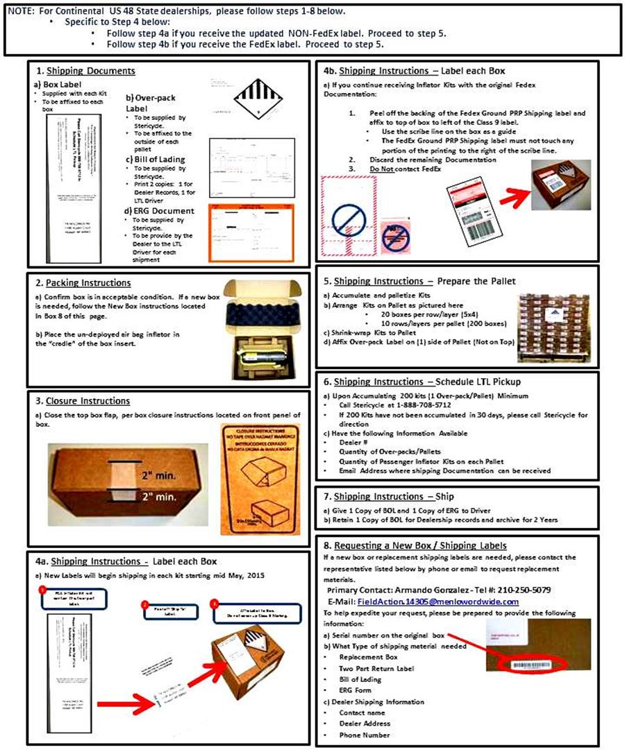
Shipping/return instructions are provided with each inflator kit.
For Continental US 48 States use the procedure on page 5 to package the original airbag inflator in the replacement kit box and return. Shipping/return instructions are also provided with each inflator kit.
All International, Mexico, Canada, Hawaii, Alaska, Puerto Rico, and US Virgin Islands dealers MUST contact the following Takata/Menlo USA representative directly for shipping instructions:
Miguel Prigadaa – Tel #: 210-250-5078 or
Email: MLGTakataRestraints_International@menloworldwide.com.
Special Tools
The following special tools are required to perform this repair:
|
wiTECH VCI Pod Kit |
|
Laptop Computer |
|
wiTECH Software |
Service Procedure
A. Replace Driver Airbag Inflator
- For DR, DH, D1, DC, DM, HB, HG, ND model vehicles, continue with Section B. Replace Driver Airbag Inflator – DR, DH, D1, DC, DM, HB, HG, ND
- For LX, L2 and LE model vehicles, continue with Section C. Replace Driver Airbag Inflator – LX, L2 and LE
B. Replace Driver Airbag Inflator – DR, DH, D1, DC, DM, HB, HG, ND
WARNING: To avoid serious or fatal injury on vehicles equipped with airbags, disable the Supplemental Restraint System (SRS) before performing this service procedure.
Disconnect and isolate the battery negative (ground) cable, then wait two minutes for the system capacitor to discharge before performing this procedure. This is the only sure way to disable the SRS. Failure to take the proper precautions could result in accidental airbag deployment.
At no time should any source of electricity be permitted near the inflator on the back of a non-deployed airbag. When carrying a non-deployed airbag, the trim cover or airbag cushion side of the unit should be pointed away from the body to minimize injury in the event of an accidental deployment.
- Use this procedure to replace the driver airbag inflator.
- For LX, L2 and LE model vehicles, continue with Section C. Replace Driver Airbag Inflator – LX, L2 and LE.
- For all other models, continue with Step 2.
- Disconnect and isolate the negative battery cable. Wait two minutes for the system capacitor to discharge before further service.
- Remove and save the two driver airbag screws that secure the driver airbag to the steering wheel armature from the underside of the steering wheel (Figure 1).
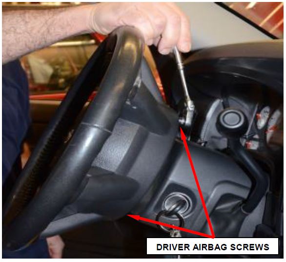 Figure 1 – Driver Airbag Screw Location
CAUTION: Do not pull on the horn switch feed pigtail wire to disengage the connector from the driver airbag housing or to disconnect the horn switch to steering wheel wire harness connection. Improper pulling on this pigtail wire or connection can result in damage to the horn switch membrane or feed circuit.
- Pull the driver airbag away from the steering wheel far enough to access the three electrical connections on the back of the driver airbag housing (Figure 2).
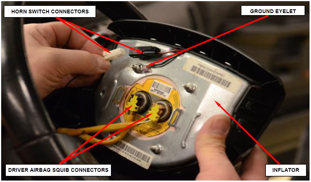 Figure 2 – Driver Airbag Electrical Connections
- Disconnect the horn switch connector, which is located on the back of the driver airbag housing (Figure 2).
CAUTION: Do not pull on the clockspring pigtail wires or pry on the connector insulator to disengage the connector from the driver airbag inflator connector receptacle. Improper removal of these pigtail wires and their connector insulators can result in damage to the airbag circuits or connector insulators.
- Disconnect the two driver airbag squib connectors. Depress the latches on each side of the connector insulator and pull the insulators straight out from the driver airbag inflator to disconnect them from the connector receptacles (Figure 3).
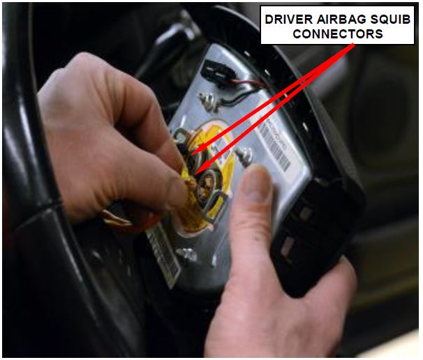 Figure 3 – Driver Airbag Squib Connectors
- Remove the driver airbag from the steering wheel.
- Place the driver airbag on a soft surface to prevent damage using the foam block provided with the inflator kit (Figure 4).
- Remove the horn switch connector from the inflator assembly using a flat head screwdriver (Figure 4).
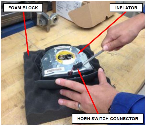 Figure 4 – Horn Switch Connector
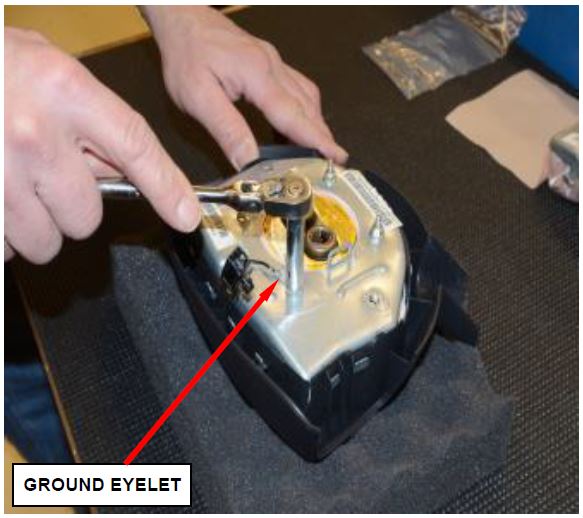
- Remove and discard the nut holding the ground eyelet to the inflator assembly and remove the ground eyelet from the stud (Figure 5).
- Remove the driver airbag cover starting with the left side by pressing down on the inflator assembly until the hooks unsnap from the windows (Figure 6).
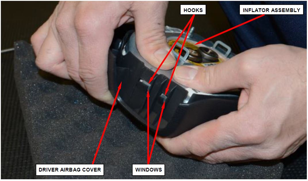 Figure 6 – Left Side Driver Airbag Cover to Inflator Assembly Hooks
- Unsnap the top hooks by pressing down on the inflator assembly until the hooks unsnap from the airbag cover windows (Figure 7).
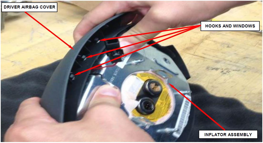 Figure 7 – Top Driver Airbag Cover to Inflator Assembly Hooks
- Unsnap the right side hooks by pressing down on the inflator until the hooks unsnap from the driver airbag cover.
- Gently pull the inflator assembly up slowly making sure that the hooks are clear from the windows on all sides (Figure 8).
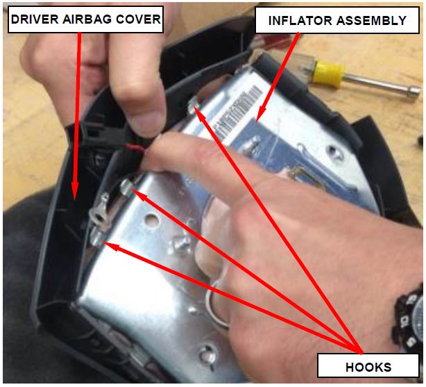 Figure 8 – Inflator Assembly to Driver Airbag Cover
- Disengage the inflator assembly from the driver airbag cover and set aside for shipping (Figure 9).
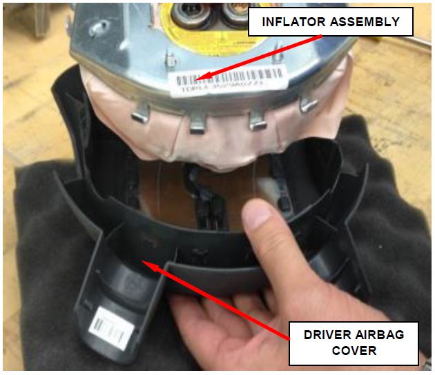 Figure 9 – Inflator Assembly to Driver Airbag Cover
- Install the new inflator assembly to the original driver airbag cover by first inserting the bottom hooks into the windows (Figure 10).
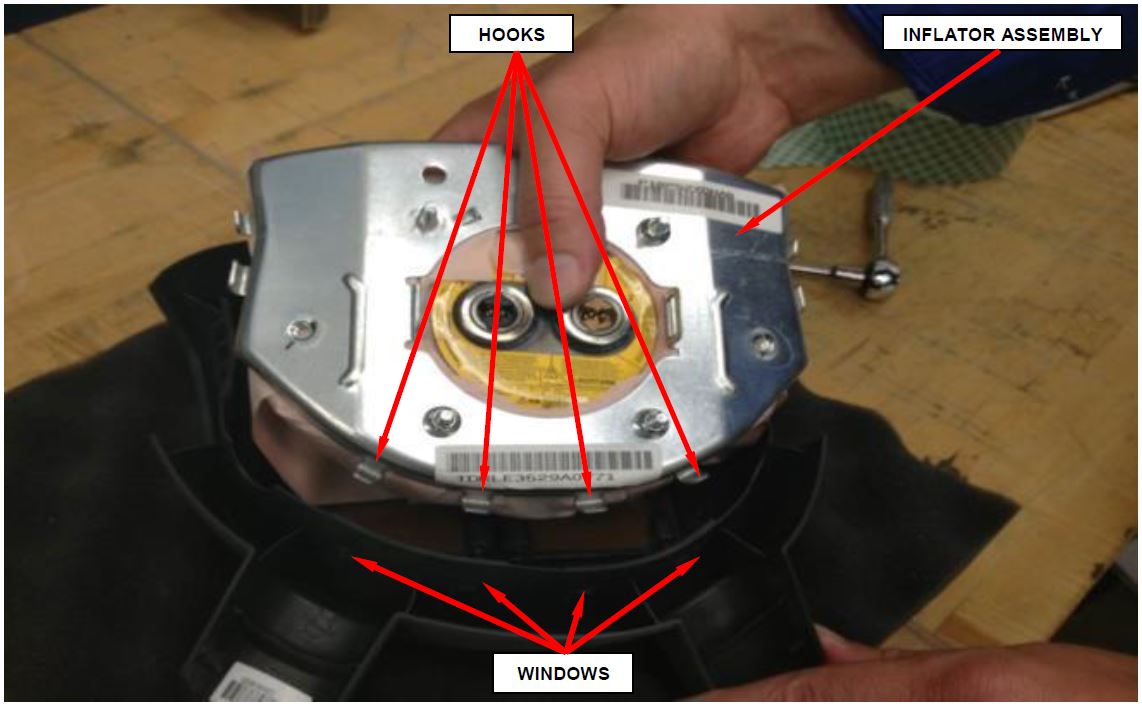 Figure 10 – Inflator Assembly to Driver Airbag Cover Hooks
- Snap the remaining hooks on all sides into place.
- Pull on the inflator assembly to fully engage the windows and hooks on all sides (Figure 11).
NOTE: Visually inspect and verify that all the hooks are fully engaged with the windows on all sides.
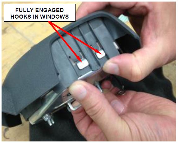 Figure 11 – Inflator Assembly Hooks
- Install the ground eyelet on the upper left stud (Figure 12).
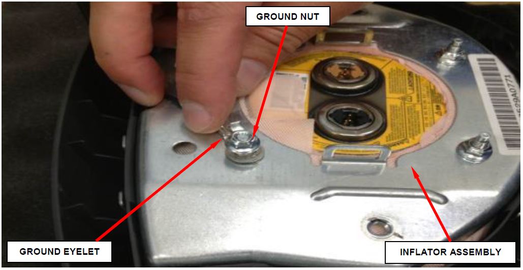 Figure 12 – Ground Eyelet to Inflator Assembly
- Install the new ground nut and tighten to 26 in. lbs. (3 N·m).
- Clip the horn switch connector to the inflator assembly (Figure 13).
- Driver airbag retrofit is complete (Figure 13).
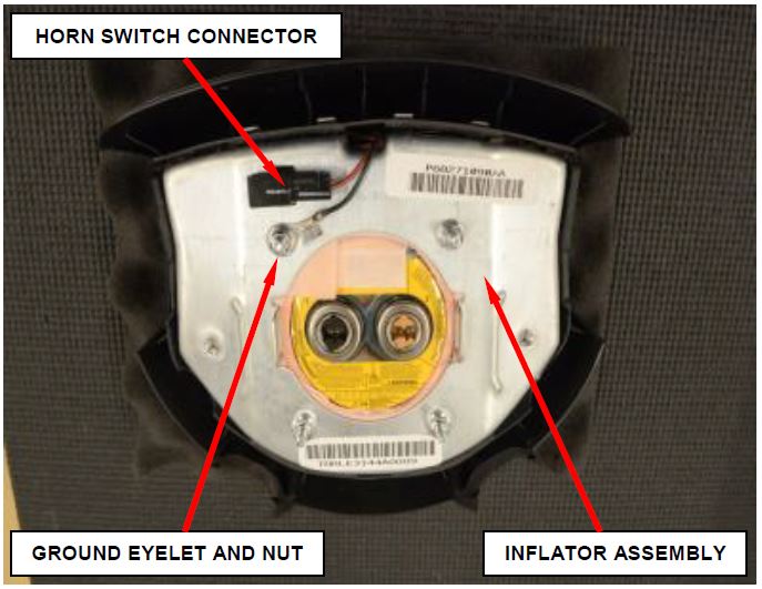 Figure 13 – Driver Airbag Assembly
- Position the driver airbag to the steering wheel to connect the three electrical connections on the back of the driver airbag housing (Figure 3).
- Connect the two driver airbag squib connectors to the driver airbag inflator assembly connector receptacles by pressing straight in on the connector. Be certain to engage each keyed and color-coded connector to the matching connector receptacle (See figure 14 and note on page 15). Be certain that each connector is fully engaged in its receptacle by listening carefully for a distinct, audible click as the connector latches snap into place (Figure 3).
NOTE: The squib connector receptacle locations on the driver airbag inflators are switched between the original Takata inflator and the TRW replacement inflator kits. Squib connectors are keyed and color coded for error proofing (Figure 14).
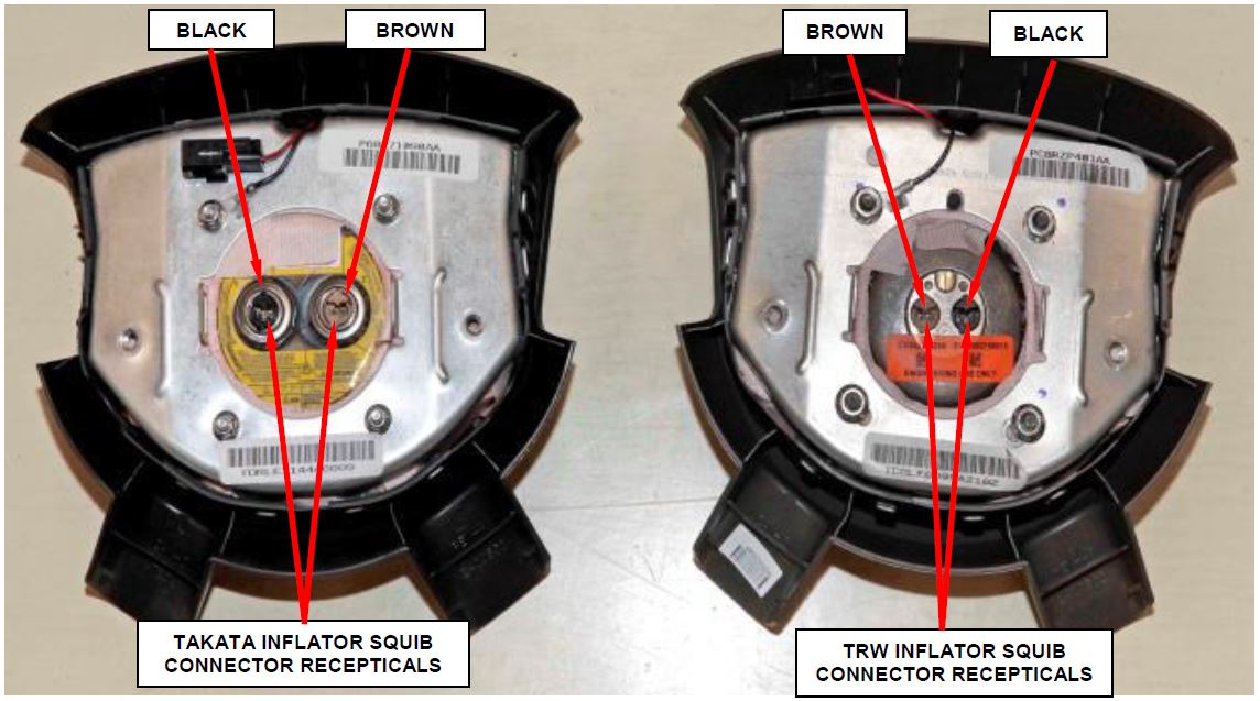 Figure 14 – Squib Connector Receptacles
- Connect the steering wheel wire harness connector for the horn switch to the horn switch connector which is located on the back of the inflator assembly (Figure 2).
- Carefully position the driver airbag in the steering wheel. Be certain that the clockspring pigtail wires and the steering wheel wire harness in the steering wheel hub area are not pinched between the driver airbag and the steering wheel armature.
- Install and tighten the two screws that secure the driver airbag to the steering wheel armature. Tighten the screws to 90 in. lbs. (10 N·m) (Figure 1).
C. Replace Driver Airbag Inflator – LX, L2 and LE
- Use this procedure to replace the driver airbag inflator.
- Disconnect and isolate the negative battery cable. Wait two minutes for the system capacitor to discharge before further service.
- Remove and save the two screws that secure the driver airbag assembly to the steering wheel armature from the underside of the steering wheel (Figure 15).
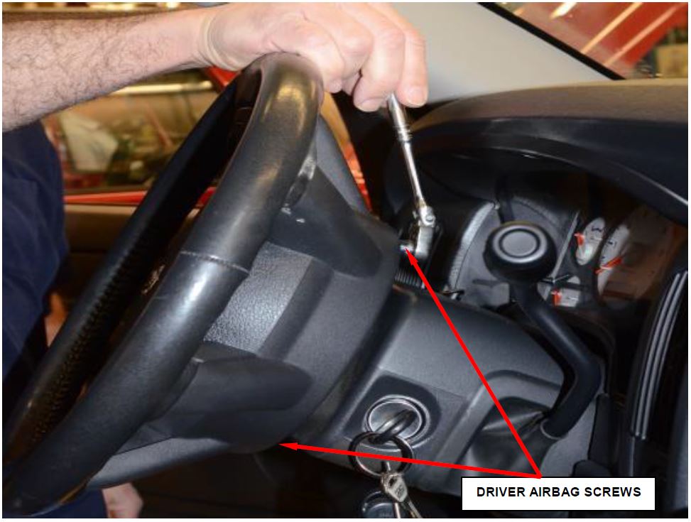 Figure 15 – Typical Driver Airbag Screw Locations
CAUTION: Do not pull on the horn switch feed pigtail wire to disengage the connector from the driver airbag housing or to disconnect the horn switch to steering wheel wire harness connection. Improper pulling on this pigtail wire or connection can result in damage to the horn switch membrane or feed circuit.
- Pull the driver airbag assembly away from the steering wheel far enough to access the three electrical connections on the back of the airbag housing (Figure 16).
- Disconnect the steering wheel wire harness connector for the horn switch from the horn switch feed pigtail wire connector, which is located on the back of the driver airbag housing (Figure 16).
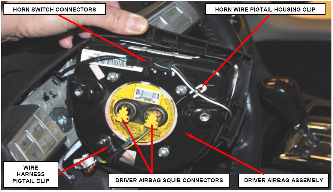 Figure 16 – Electrical Connectors
CAUTION: Do not pull on the clockspring pigtail wires or pry on the connector insulator to disengage the connector from the driver airbag inflator connector receptacle. Improper removal of these pigtail wires and their connector insulators can result in damage to the airbag circuits or connector insulators.
- Disconnect the driver airbag squib connectors. Depress the latches on each side of the connector insulator and pull the insulators straight out from the airbag inflator to disconnect them from the connector receptacles (Figure 17).
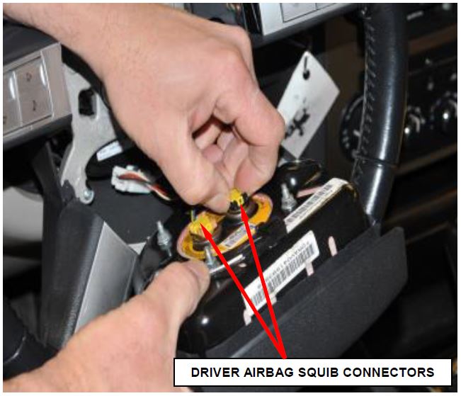 Figure 17 – Airbag Squib Connectors
- Disengage the wire harness pigtail clip from the housing (Figure 18).
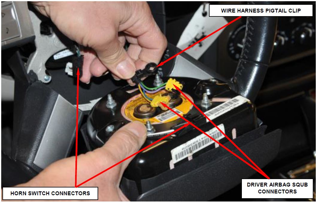 Figure 18 – Wire Harness Pigtail Clip
- Remove the driver airbag assembly from the steering wheel.
- Place the driver airbag on a soft surface to prevent damage using the foam block provided with the inflator kit.
- Remove the horn switch connector from the housing (Figure 19).
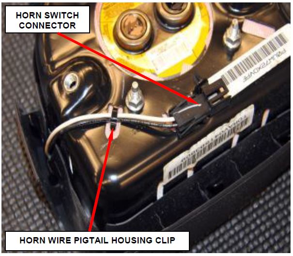 Figure 19 – Horn Connector
- Remove the driver airbag cover starting with the left side by pressing down on the driver airbag housing until the hooks unsnap from the windows (Figure 20).
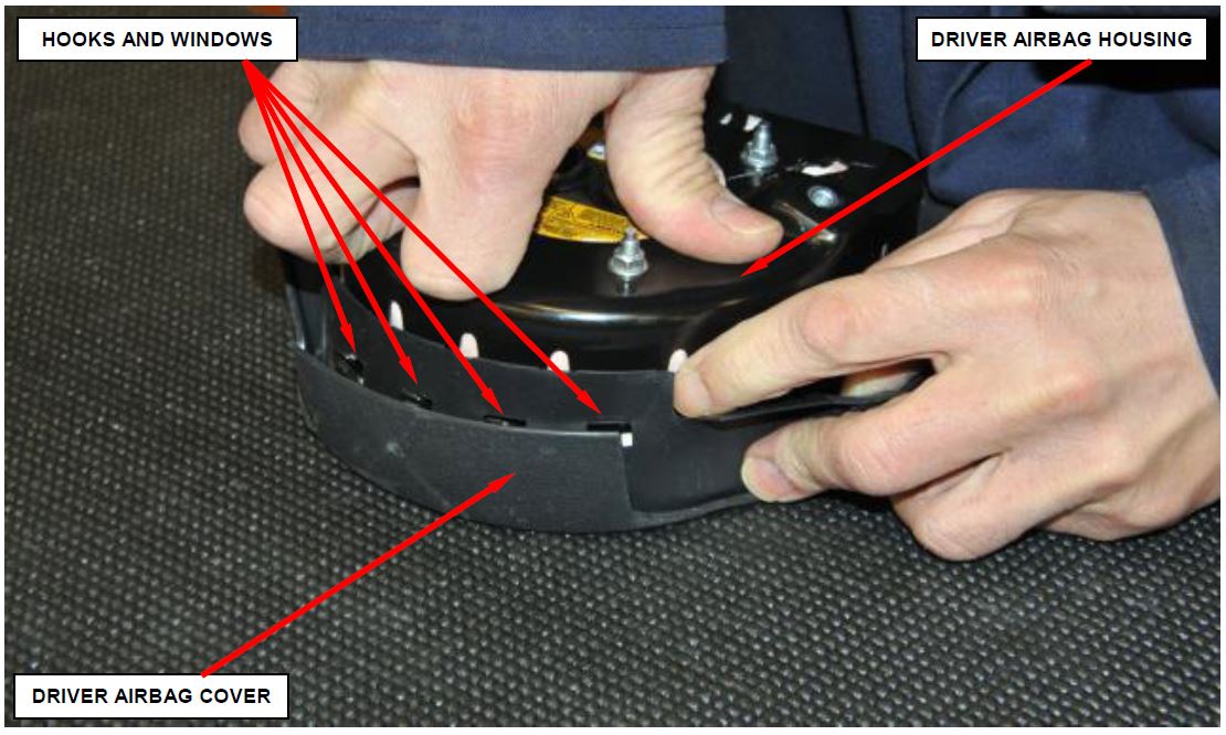 Figure 20 – Driver Airbag Cover
- Unsnap the bottom hooks by pressing down on the housing until the hooks unsnap from the cover.
- Unsnap the right side hooks by pressing down on the housing until the hooks unsnap from the cover.
- Gently pull the housing up slowly making sure that the hooks are clear from the windows on all sides.
- Disengage the old inflator assembly from the driver airbag cover and set aside for shipping.
- Install the new inflator assembly to the original driver airbag cover by first inserting the top hooks into the windows (Figure 21).
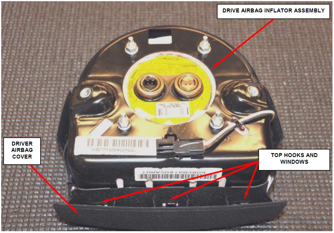 Figure 21 – Driver Airbag Inflator Assembly to Cover
- Snap the remaining hooks in the windows on all sides into place.
- Pull on the driver airbag inflator assembly to fully engage the hooks and windows on all sides of the driver airbag cover (Figure 22).
NOTE: Visually inspect and verify that all the hooks are fully engaged with the windows on all sides.
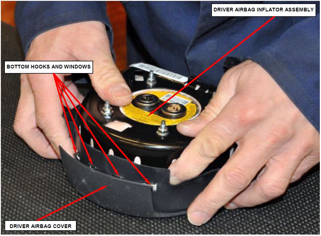 Figure 22 – Verify Hook and Window Engagement
- Clip the horn switch connector to the driver airbag housing bracket (Figure 23).
- Engage the horn switch wire harness pigtail to the driver airbag housing clip (Figure 23).
- Driver airbag retrofit is complete (Figure 23).
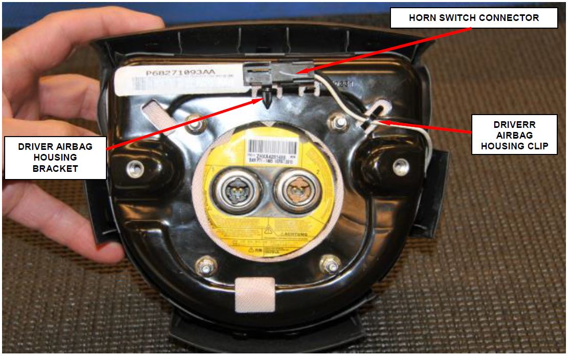 Figure 23 – Horn Switch Connector
- Position the driver airbag to the steering wheel to connect the three electrical connections on the back of the airbag housing.
- Connect the two driver airbag squib connectors to the airbag inflator connector receptacles by pressing straight in on the connector. Be certain to engage each keyed and color-coded connector to the matching connector receptacle. Be certain that each connector is fully engaged in its receptacle by listening carefully for a distinct, audible click as the connector latches snap into place (Figure 16).
NOTE: The squib connector receptacle locations on the driver airbag inflators are switched between the original Takata inflator and the TRW replacement inflator kits. Squib connectors are keyed and color coded for error proofing (Figure 24).
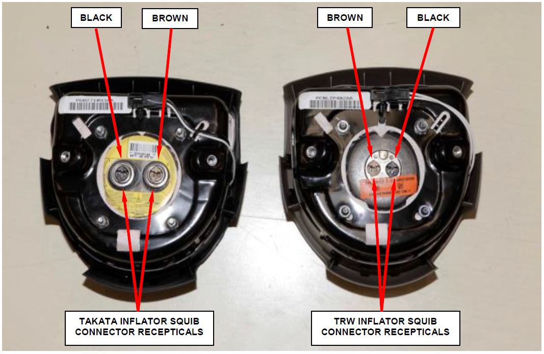 Figure 24 – Squib Connector Receptacles
- Connect the steering wheel wire harness connector for the horn switch to the horn switch connector which is located on the back of the driver airbag housing and clip the wire harness pigtail to the housing (Figure 16).
- Carefully position the driver airbag in the steering wheel. Be certain that the clockspring pigtail wires and the steering wheel wire harness in the steering wheel hub area are not pinched between the driver airbag and the steering wheel armature.
- Install and tighten the two screws that secure the driver airbag assembly to the steering wheel armature. Tighten the screws to 90 in. lbs. (10 N·m) (Figure 15).
- Continue with nhtsa-15v-313-driver-airbag-inflator-2004-2011-chrysler-dodge-ram/12">Section D. Supplemental Restraint System (SRS) Verification Test.
D. Supplemental Restraint System (SRS) Verification Test
NOTE: During the following test, the negative battery cable remains disconnected and isolated during steps 1 and 2 of the Supplemental Restraint System (SRS) Verification Test.
NOTE: The wiTECH scan tool must be used to perform this recall. This procedure must be performed with software release level 15.04 or higher.
- Connect the wiTECH VCI pod to the vehicle data link connector located under the steering column.
- Turn the ignition switch to the “ON” position and exit the vehicle and close the doors.
- Check to be certain that nobody is in the vehicle, then connect the battery negative cable(s).
- Open the wiTECH Diagnostic application.
- Starting at the “Select Tool” screen, select the row/tool for the wiPOD device you are using, then select “Next”.
- Enter your “User id” and “Password”, then select “Finish”.
NOTE: If wiTECH is unable to identify the connected vehicle, click on the Launch DRB III button and use the DRB III Emulator tool.
- Clear all DTC’s in all modules using either the wiTECH or the DRB III mode.
NOTE: Any active Diagnostic Trouble Codes (DTC’s) may require an additional key cycle from “ON” to “OFF” to change DTC status from “active” to “stored”.
- Turn the ignition switch to the “OFF” position for about 15 seconds, and then back to the “ON” Observe the airbag indicator in the instrument cluster.
- The airbag indicator in the instrument cluster should illuminate for six to eight seconds, and then go out. This indicates that the SRS is functioning normally and that the repairs are complete. Turn the ignition to the “OFF” position, remove the wiPOD and return the vehicle to the customer.
- If the airbag indicator fails to light or the light and stays ON, there is still an active SRS fault or malfunction. Refer to the appropriate diagnostic information to diagnose the
- Close the hood, remove the wiTECH VCI pod.
- Use the procedure on pages 4 and 5 to return the original inflator kit.
- Return the vehicle to the customer.
Completion Reporting and Reimbursement
Claims for vehicles that have been serviced must be submitted on the DealerCONNECT Claim Entry Screen located on the Service tab. Claims submitted will be used by FCA US LLC to record recall service completions and provide dealer payments.
Use one of the following labor operation numbers and time allowances:
| Labor Operation Number | Time Allowance | |
|---|---|---|
| Replace Driver Airbag Inflator and Conduct Supplemental Restraint System Verification Test (DR, DH, D1, DC, DM, HB, HG, ND models) | 08-R2-51-82 | 0.7 hours |
| Replace Driver Airbag Inflator and Conduct Supplemental Restraint System Verification Test (LX, L2, LE models) | 08-R2-51-83 | 0.5 hours |
NOTE: See the Warranty Administration Manual, Recall Claim Processing Section, for complete recall claim processing instructions.
Dealer Notification
To view this notification on DealerCONNECT, select “Global Recall System” on the Service tab, then click on the description of this notification.
Owner Notification and Service Scheduling
All involved vehicle owners known to FCA US LLC are being notified of the service requirement by first class mail. They are requested to schedule appointments for this service with their dealers. A generic copy of the owner letter is attached.
Enclosed with each owner letter is an Owner Notification postcard to allow owners to update our records if applicable.
Vehicle Lists, Global Recall System, VIP and Dealer Follow Up
All involved vehicles have been entered into the DealerCONNECT Global Recall System (GRS) and Vehicle Information Plus (VIP) for dealer inquiry as needed.
GRS provides involved dealers with an updated VIN list of their incomplete vehicles. The owner’s name, address and phone number are listed if known. Completed vehicles are removed from GRS within several days of repair claim submission.
To use this system, click on the “Service” tab and then click on “Global Recall System.” Your dealer’s VIN list for each recall displayed can be sorted by: those vehicles that were unsold at recall launch, those with a phone number, city, zip code, or VIN sequence.
Dealers must perform this repair on all unsold vehicles before retail delivery. Dealers should also use the VIN list to follow up with all owners to schedule appointments for this repair.
Recall VIN lists may contain confidential, restricted owner name and address information that was obtained from the Department of Motor Vehicles of various states. Use of this information is permitted for this recall only and is strictly prohibited from all other use.
Additional Information
If you have any questions or need assistance in completing this action, please contact your Service and Parts District Manager.
Customer Services / Field Operations
FCA US LLC
DRIVER AIRBAG INFLATOR
IMPORTANT SAFETY RECALL
R25 / NHTSA 15V-313
This notice applies to your vehicle (VIN: xxxxxxxxxxxxxxxxx).
This notification letter is sent to you in accordance with the National Traffic and Motor Vehicle Safety Act.
Dear: (Name)
FCA US LLC has decided that a defect, which relates to motor vehicle safety, exists in certain 2004 through 2009 model year Dodge RAM 1500/2500/3500 Pickup, 2004 through 2008 model year Dodge Durango, 2007 through 2008 model year Chrysler Aspen, 2005 through 2010 model year Chrysler 300/Dodge Charger/Dodge Magnum, and 2005 through 2011 model year Dodge Dakota vehicles.
| The problem is… | The driver airbag inflator housing in your vehicle may rupture, due to excessive internal pressure, during normal airbag deployment events. This condition is more likely to occur if your vehicle has been exposed to high levels of absolute humidity for extended periods of time. An inflator rupture, during airbag deployment events, could result in metal fragments striking and potentially seriously injuring the vehicle occupants. |
| What your dealer will do… | FCA will repair your vehicle free of charge (parts and labor). To do this, your dealer will replace your driver airbag inflator. The work will take up to 1 hour to complete. However, additional time may be necessary depending on service schedules. |
| What you must do to ensure your safety… | Simply contact your Chrysler, Jeep, Dodge or RAM dealer right away to schedule a service appointment. Please bring this letter with you to your dealer. |
| If you need help… | If you have questions or concerns which your dealer is unable to resolve, please contact the FCA Recall Assistance Center at 1-800-853-1403. |
Please help us update our records by filling out the attached prepaid postcard if any of the conditions listed on the card apply to you or your vehicle. If you have further questions go to recalls.mopar.com.
If you have already experienced this specific condition and have paid to have it repaired, you may visit www.fcarecallreimbursement.com to submit your reimbursement request online or you can mail your original receipts and proof of payment to the following address for reimbursement consideration: FCA Customer Assistance, P.O. Box 21-8004, Auburn Hills, MI 48321-8007, Attention: Recall Reimbursement. Once we receive and verify the required documents, reimbursement will be sent to you within 60 days. If you’ve had previous repairs and/or reimbursement you may still need to have the recall repair performed on your vehicle.
If your dealer fails or is unable to remedy this defect without charge and within a reasonable time, you may submit a written complaint to the Administrator, National Highway Traffic Safety Administration, 1200 New Jersey Ave., S.E., Washington, DC 20590, or you can call the toll-free Vehicle Safety Hotline at 1-888-327-4236 (TTY 1-800-424-9153), or go to safercar.gov.
We’re sorry for any inconvenience, but we are sincerely concerned about your safety. Thank you for your attention to this important matter.
Customer Services / Field Operations
FCA US LLC
Note to lessors receiving this recall: Federal regulation requires that you forward this recall notice to the lessee within 10 days.
 Loading...
 Loading...
