| “This site contains affiliate links for which OEMDTC may be compensated” |
February 8, 2018
Being able to shift the transmission without pushing the brake pedal and/or without a key in the ignition can increase the risk of an unintended vehicle rollaway that may result in personal injury or a crash.
NHTSA Campaign Number: 18V100
Manufacturer Chrysler (FCA US LLC)
Components POWER TRAIN
Potential Number of Units Affected 180,462
Summary
Chrysler (FCA US LLC) is recalling certain 2017-2018 RAM
 1500, 2500, 3500, 3500 Cab Chassis, 4500 Cab Chassis, and 5500 Cab Chassis vehicles, all equipped with a column shifter. Pushing the brake pedal for prolonged periods when the vehicle is running and in PARK may cause the Brake Transmission Shift Interlock (BTSI) pin to stick in the open position. With the pin in the open position, the transmission can be shifted out of PARK into any gear without pushing the brake pedal or having the key in the ignition.
Remedy
Chrysler will notify owners and dealers will update the Body Control Module software. Dealers will also test the BTSI operation, replacing the solenoid as necessary. The recall began February 26, 2018. Owners may contact Chrysler
 customer service at 1-800-853-1403. Chrysler
 ’s number for this recall is U11.
Notes
Owners may also contact the National Highway Traffic Safety Administration Vehicle Safety Hotline at 1-888-327-4236 (TTY 1-800-424-9153), or go to www.safercar.gov.
Check if your Vehicle has a Recall
Revised April 2018
Dealer Service Instructions for:
Safety Recall U11 / NHTSA 18V-100 Brake Transmission Shift Interlock
NOTE: Page 1 “Models” changed to “Remedy Available”. Page 19 and Page 20 “U11 Addendum Card” changed to “BTSI Addendum Card”.
NOTE: For all vehicles that were previously repaired under this safety recall (prior to February 18, 2018) drive the vehicle until at least 10 MPH is achieved for 5 seconds. For 2018 MY vehicles also perform the battery disconnect and BUS cycle included in steps 17 through 19 in Section C.
Remedy Available √
| 2017 – 2018 | (DS) | RAM 1500 Pickup 1500 Pickup |
| 2017 – 2018 | (DJ) | RAM 2500 Pickup 2500 Pickup |
| 2017 – 2018 | (D2) | RAM 3500 Pickup 3500 Pickup |
| 2017 – 2018 | (DD) | RAM 3500 Chassis Cab 3500 Chassis Cab |
| 2017 – 2018 | (DF) | RAM 3500 10K GVWR Chassis Cab 3500 10K GVWR Chassis Cab |
| 2017 – 2018 | (DP) | RAM 4500/5500 Chassis Cab 4500/5500 Chassis Cab |
NOTE: This recall applies only to the above vehicles equipped with a column shift automatic transmission. This safety recall does not affect vehicles equipped with a rotary or floor shifter or manual transmission.
| IMPORTANT: Some of the involved vehicles may be in dealer new vehicle inventory. Federal law requires you to complete this recall service on these vehicles before retail delivery. Dealers should also consider this requirement to apply to used vehicle inventory and should perform this recall on vehicles in for service. Involved vehicles can be determined by using the VIP inquiry process. |
Subject
The Brake Transmission Shift Interlock (BTSI) locking pin on about 180,400 of the above vehicles may become stuck in the open position. A BTSI locking pin stuck in the open position may allow the transmission to be shifted out of PARK and to any gear position without depression of the brake pedal and/or without the key in the ignition, if a key is applicable, or while the ignition is in the “OFF” mode. The ability to shift the transmission out of the PARK position while the ignition is in the “OFF” mode or without a key in the ignition or a brake pedal application, increases the risk for an unintended vehicle rollaway that may result in a vehicle crash or injury without prior warning.
WARNING: Never use the PARK position as a substitute for the parking brake. Always apply the parking brake fully when parked to guard against vehicle movement and possible injury or damage. Refer to your owner’s manual for additional information regarding proper parking brake usage.
Repair
Test the BTSI operation and replace if necessary. Reprogram the Body Control Module (BCM) with new software and place an addendum card in the owner manual. Instruct the vehicle owner to read the addendum card in order to become familiar with the revised BTSI operation.
Parts Information
Perform the Service Procedure Section A. BTSI Inspection before ordering part.
| Models | Sales Codes |
|---|---|
| DS – All | DFP – 6-SPD Automatic 66RFE Transmission |
| DJ – All | DG7 – 6-SPD Automatic 68RFE Transmission |
| DD – DFP | DG1 – 6-SPD Automatic 65RFE Transmission |
| D2 – DFP or DG7 | |
| DF – DFP |
| Description | Part Number |
|---|---|
| Bracket, Gearshift (Includes BTSI) | CSZHT791AA |
| Models | Sales Codes |
|---|---|
| DP – All | DF2 – 6-SPD Automatic Aisin AS69RC Transmission |
| DD – DF2 or DF3 | DF3 – 6-SPD Automatic Aisin AS66RC Transmission |
| D2 – DF2 | |
| DF – DF2 or DF3 |
| Description | Part Number |
|---|---|
| Bracket, Gearshift (Includes BTSI) | CSZHT792AA |
Due to the small number of involved vehicles expected to require gearshift bracket / BTSI replacement, no parts will be distributed initially. The gearshift bracket / BTSI should be ordered only after inspection determines that replacement is required. Very few vehicles are expected to require gearshift bracket / BTSI replacement.
Parts Return
No parts return required for this campaign.
Special Tools
The following special tools are required to perform this repair:
| wiTECH micro pod II |
| Laptop Computer |
| wiTECH Software |
Service Procedure
A. BTSI Inspection
NOTE: This process is to determine if the BTSI needs to be replaced.
- While sitting in the driver’s seat, apply the parking brake.
- With the ignition switch in the “OFF” position, attempt to shift the transmission into any gear.
- If the shifter is blocked then continue with Step 3.
- If the shifter moves freely, then follow the repair procedure to replace the BTSI. Proceed to Section B. Gearshift Bracket / BTSI Assembly Replacement.
- Place the ignition switch in the “RUN” position and leave the shift lever in the “PARK” position. Only minimal force is required, do not force the shift lever.
- Turn off the radio, Heating, Ventilating, and Air Conditioning (HVAC), and any other accessories that are making noise. Also have all vehicle windows in the up and closed position to reduce outside noises.
NOTE: Do not move the shift lever from the “PARK” position during Steps 5 through 9.
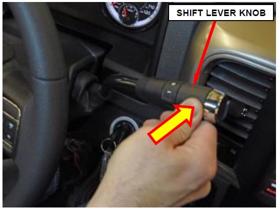
- Place your hand on the shift lever knob and push lightly on the shift lever toward the instrument panel. This will allow you to feel a click sensation from BTSI solenoid pin movement when the brake pedal is applied and released (Figure 1).
- Listen for a click sound from the BTSI solenoid pin movement while also feeling for the corresponding click sensation in the shift lever when the brake is applied and released.
Figure 1 – Push Lightly On Shift Lever
Knob Toward Instrument Panel To Feel
BTSI Solenoid Pin Movement
- After you are familiar with both the sound and feel of the BTSI pin movement in Steps 5 and 6, continue with Step 8.
- Place your hand on the shift lever knob as instructed in Step 5 then apply and hold the brake pedal for a count of five seconds.
- After five seconds of holding the brake pedal down, release the brake pedal while both listening and feeling for the click of the BTSI pin movement. The sound and feel of the BTSI pin movement should occur immediately within 0-2 seconds upon release of the brake pedal.
- If the BTSI pin could be heard and felt moving within 0-2 seconds, then the BTSI inspection process is complete and the gearshift bracket / BTSI assembly does not need to be replaced. Place the ignition switch in the “OFF” position then proceed to Section C. Reprogram Body Control Module (BCM).
- If the BTSI pin could not be heard and felt moving within 0-2 seconds, then continue with Step 10.
NOTE: For the BTSI test in steps 10 and 11, do not place your hand on the shift lever until instructed to do so.
- Do not place your hand on the shift lever. With the ignition switch in the “RUN” position, apply and hold the brake pedal for a count of five seconds.
- After five seconds of holding the brake pedal down, release the brake pedal. Wait exactly 2 seconds then attempt to move the shift lever out of the “PARK” position. Only minimal force is required, do not force the shift lever.
- If the shift lever cannot be moved from the “PARK” position 2 seconds after the brake pedal is released, the BTSI inspection process is complete and the gearshift bracket / BTSI assembly does not need to be replaced. Proceed to Section C. Reprogram Body Control Module (BCM).
- If the shift lever can be moved out of the “PARK” position 2 seconds after the brake pedal is released, then the gearshift bracket / BTSI assembly must be replaced. Proceed to Section B. Gearshift Bracket / BTSI Assembly Replacement.
B. Gearshift Bracket / BTSI Assembly Replacement
- Open the vehicle hood
- Disconnect the negative battery cable terminal from the battery(s).
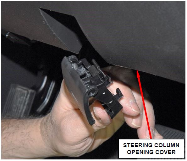
- Using a trim stick C-4755 or equivalent, disengage the retainer clip that secures the hood release handle to the steering column opening cover, and remove the hood release handle from the cover (Figure 2).
Figure 2 – Hood Release Handle
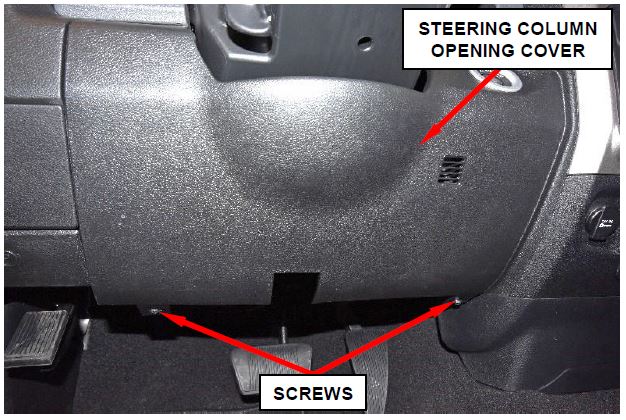
- Remove and save the two screws that secure the bottom of the steering column opening cover to the instrument panel (Figure 3).
- Using a trim stick C-4775 or equivalent, release the eight spring clips that attach the steering column opening cover to the instrument panel (Figure 3)
Figure 3 – Steering Column Opening Cover
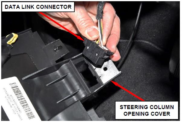
- Remove the data link connector from the steering column opening cover by pressing in the tabs and pushing the connector through the opening on the back side of the cover (Figure 4).
- If equipped: Disconnect the electrical connectors for any electrical devices from the steering column opening cover.
- Remove and save the steering column opening cover.
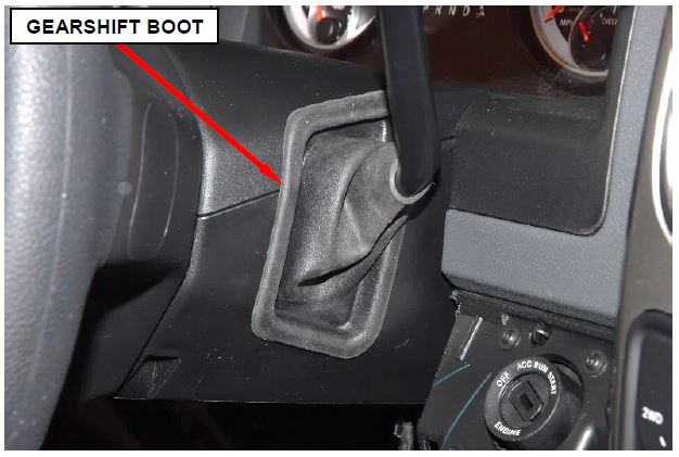
- Using a trim stick, disengage the gearshift boot from the steering column shrouds (Figure 5).
Figure 4 – Data Link Connector
Figure 5 – Gearshift Boot
NOTE: There are snap connections near the instrument cluster and between the shroud and the steering wheel that secure the upper and lower shroud.
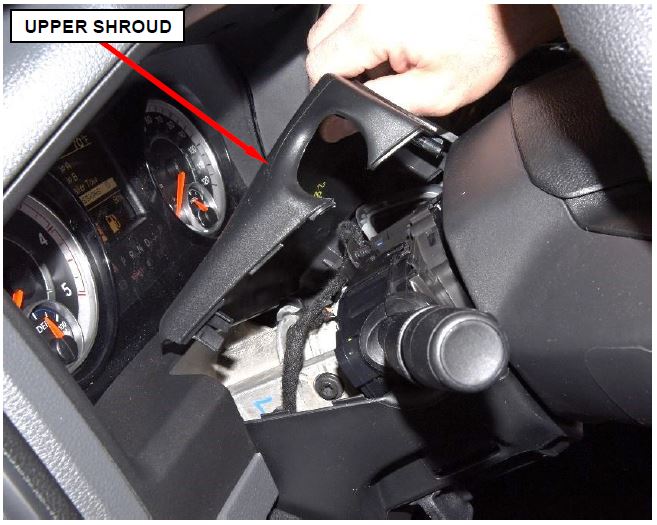
- Remove and save the upper steering column shroud by pushing gently inward and upward on both sides of the upper shroud just above the joint line to the lower shroud to release the snap features that secure the shrouds together (Figure 7).
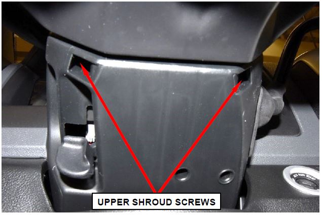
Figure 6 – Upper Shroud Screws
Figure 7 – Steering Column Upper Shroud
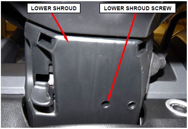
- Remove and save the T20 starhead screw that retains the lower shroud to the steering column (Figure 8).
Figure 8 – Steering Column Lower Shroud
- Carefully move the lower shroud to clear the steering column tilt lever then remove and save the lower shroud. (Figure 8).
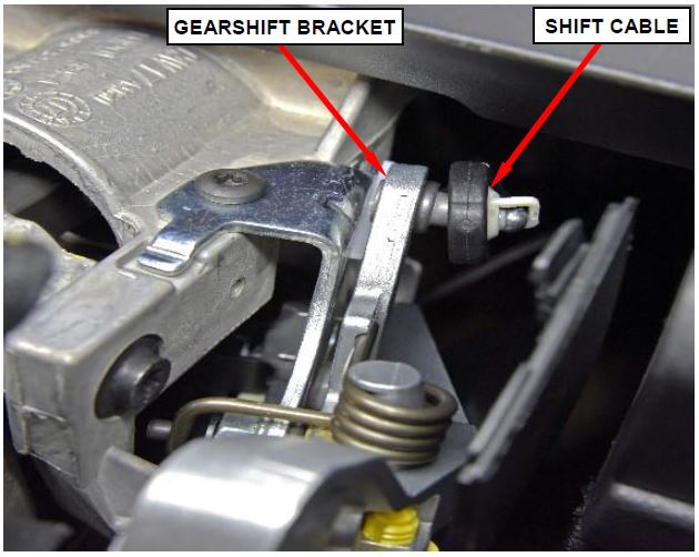
- Disconnect the shift cable from the gearshift bracket (Figure 9).
Figure 9 – Shift Cable
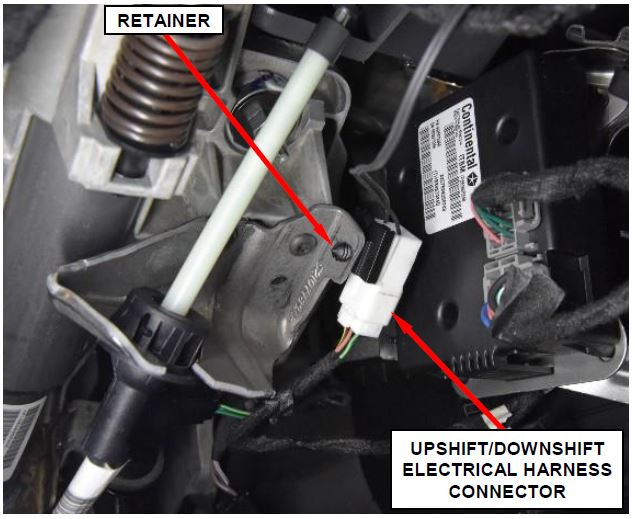
- Disconnect the upshift/downshift electrical harness connector (Figure 10).
- Release the upshift/downshift electrical harness connector retainer (Figure 10).
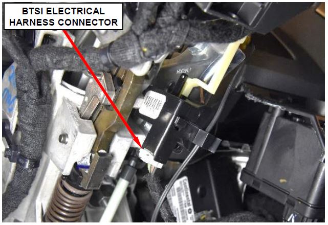
- Disconnect the BTSI electrical harness connector (Figure 11).
Figure 10 – Upshift/Downshift Electrical Harness
Figure 11 – BTSI Electrical Harness
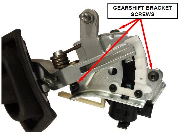
- Remove and save the three T27 star-head screws securing the gearshift bracket / BTSI assembly to the steering column (Figure 12).
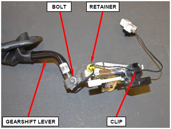
- Remove the gearshift bracket / BTSI assembly with shift lever from the steering column then transfer to bench (Figure 13).
- Remove the upshift/downshift electrical harness from the retaining clip (Figure 13).
- Release the upshift/downshift electrical harness retainer from the gearshift bracket / BTSI assembly (Figure 13).
- Remove and save the E10 starhead pinch bolt securing the shift lever to the gearshift bracket / BTSI assembly (Figure 13).
- Remove and save the gearshift lever from the gearshift bracket / BTSI assembly (Figure 13).
Figure 12 – Gearshift Bracket / BTSI Assembly Screws
Figure 13 – Gearshift Lever
- Discard the old gearshift bracket / BTSI assembly.
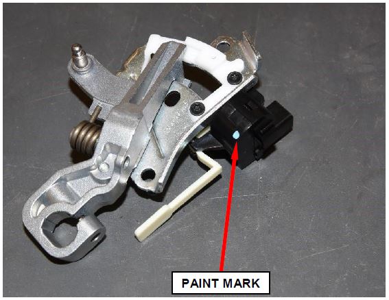
- Verify the new gearshift bracket / BTSI assembly to be used has a paint mark on the BTSI solenoid (Figure 14).
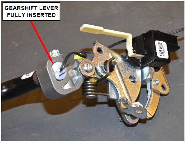
- Install the gearshift lever to the new gearshift bracket / BTSI assembly and ensure the gearshift lever is fully inserted into the gearshift bracket (Figure 15).
Figure 14 – Gearshift Bracket / BTSI Assembly Paint Mark Verification
- Install the E10 star-head pinch bolt securing the shift lever to the gearshift bracket / BTSI assembly. Tighten the pinch bolt to 11 N·m (97 in. lbs.) (Figure 13). Ensure shift lever is properly seated and not loose after tightening.
- Attach the upshift/downshift electrical harness retainer to the gearshift bracket / BTSI assembly (Figure 13).
- Install the upshift/downshift electrical harness to the retaining clip (Figure 13).
- Install the gearshift bracket / BTSI assembly with shift lever to the steering column.
Figure 15 – Gearshift Lever Insertion
- Install the three T27 star-head screws securing the gearshift bracket / BTSI assembly to the steering column. Tighten the screws to 10 N·m (89 in. lbs.) (Figure 12).
- Connect the BTSI electrical harness connector (Figure 11).
- Install the upshift/downshift electrical harness connector retainer (Figure 10).
- Connect the upshift/downshift electrical harness connector (Figure 10).
- Connect the shift cable to the gearshift bracket (Figure 9).
- Carefully position the lower shroud over the steering column tilt lever and onto the steering column (Figure 8).
- Install the T20 star-head screw that retains the lower shroud to the steering column. Tighten the screw to 2.3 N·m (20 in. lbs.) (Figure 8).
- Attach the upper steering column shroud by pushing gently inward on both sides of the upper shroud just above the joint line to the lower shroud and attach to the lower shroud using the snap features (Figure 7).
- Install the two T20 star-head screws that attach the lower steering column shroud to the upper shroud. Tighten the screws to 1.3 N·m (12 in. lbs.) (Figure 6).
- Attach the shift boot to the upper and lower steering column shrouds (Figure 5).
- If equipped: Connect the electrical connectors for any electrical devices to the steering column opening cover.
- Install the data link connector to the steering column opening cover by pushing the connector through the opening on the back side of the cover and fully engaging the lock tabs of the connector (Figure 4).
- Attach the steering column opening cover to the instrument panel with the eight spring clips (Figure 3).
- Install the two screws that secure the steering column opening cover to the instrument panel. Tighten the screws to 3.6 N·m (32 in. lbs.) (Figure 3).
- Position the hood release handle onto the steering column opening cover and fully engage the retainer clip that secures the hood release handle to the steering column opening cover (Figure 2).
- Connect the negative battery cable terminal to the battery(s).
- Proceed to Section C. Reprogram Body Control Module (BCM).
C. Reprogram Body Control Module (BCM)
NOTE: The wiTECH scan tool must be used to perform this recall. The wiTECH software is required to be at the latest release level before performing this procedure. If the reprogramming flash for the BCM is aborted or interrupted, repeat the procedure. The BCM must be at the latest calibration level after completing this recall.
- Open the hood. Install a battery charger
 and verify that the charging rate provides 13.0 to 13.5 volts. Do not allow the charger to time out during the flash process. Set the battery charger timer (if so equipped) to continuous charge.
NOTE: Use an accurate stand-alone voltmeter. The battery charger volt meter may not be sufficiently accurate. Voltages outside of the specified range will cause an unsuccessful flash. If voltage reading is too high, apply an electrical load by activating the park or headlamps and/or HVAC blower motor to lower the voltage.
- Connect the wiTECH micro pod II to the vehicle data link connector.
- Place the ignition in the “RUN” position.
- Open the wiTECH 2.0 website.
- Enter your “User id” and “Password” and your “Dealer Code”, then select “Finish” at the bottom of the screen.
- From the “Vehicle Selection” screen, select the vehicle to be updated.
- From the “Action Items” screen, select the “Topology” tab.
- From the “Topology” tab, select the “BCM” icon for the module requiring updating.
- From the “Flash” tab, compare the “Current Electronic Control Unit (ECU) Part Number” with the “New ECU Part Number” listed.
- If the “Current ECU part Number” is the same as the “New Part Number”, proceed to Step 14.
- If the “Current ECU part Number” is NOT the same as the “New Part Number”, continue with Step 10.
- Read the flash special instructions page. Select “OK” to continue.
- From the flash ECU agreement page, agree to terms by checking the box.
- Select “Flash ECU” and then follow the wiTECH screen instructions to complete the flash.
- Select “Guided Diagnosis” under the “Activities” column.
- Select “Restore Vehicle Configuration” and click “Continue”, then follow the wiTECH screen instructions to complete the vehicle configuration.
- From the “Topology” screen, select the “All DTCs” tab to view the DTCs.
- Select “Clear All DTCs” and then select “Close”.
- For 2018 MY only, Disconnect the negative battery cable for 60 seconds then reconnect the negative battery cable.
- For 2018 MY only, turn the ignition to the ON position then turn the ignition to the OFF position and allow the BUS to go to sleep and wait one additional minute.
- For 2018 MY only, turn the ignition to the ON position and verify the HVAC temperature control functionality.
- Place the ignition in the “OFF” position and then remove the wiTECH micro pod II device from the vehicle.
- Remove the battery charger from the vehicle.
- Close the vehicle hood.
- Drive the vehicle until at least 10 MPH is achieved for 5 seconds.
NOTE: Step 23 must be performed prior to returning the vehicle to the customer.
- Before returning the vehicle to the customer, confirm that the vehicle is in Customer Mode.
NOTE: All vehicles that have software update performed will require an addendum card be provided to the vehicle owner.
- Process Steps to obtain the BTSI Addendum Card:
a. Access the “DealerCONNECT” website.
b. Select the “Recall Central” link.
c. Locate the “Repair Information” section.
d. Select the “BTSI Addendum Card” link in the Repair Information section.
e. Print a copy of the BTSI addendum card.
f. Give the addendum card to the vehicle owner and advise the vehicle owner to read the addendum card for information regarding how the new software changes the gear shift lever interlock operation for enhanced vehicle safety.
Sample: BTSI Addendum Card
| ____________________________________________________________________
2013MY-2018MY Owner Addendum Card The purpose of this addendum card is to explain the change in the vehicle functionality after receiving the software flash. Vehicle Remedy This vehicle received updated software that releases the Brake Transmission Interlock (BTSI) locking pin after 3 minutes of applying the brake while the vehicle is in Park. Impact to Owner When applying the brake for more than 3 minutes while the vehicle is on and in park, the vehicle will require the user to release the brake and then reapply the brake in order to shift the vehicle out of Park.
Note: Please place this document in the Glove Box of the vehicle. |
 Loading...
Completion Reporting and Reimbursement
Claims for vehicles that have been serviced must be submitted on the DealerCONNECT Claim Entry Screen located on the Service tab. Claims paid will be used by FCA to record recall service completions and provide dealer payments.
Use one of the following labor operation numbers and time allowances:
| Labor Operation Number | Time Allowance | |
|---|---|---|
| Inspect BTSI Functionality and Verify BCM Software Level (2017-2018 Model Year) | 19-U1-11-81 | 0.2 hours |
| Inspect BTSI Functionality and Perform BCM Software Update (2017 Model Year Only) | 19-U1-11-82 | 0.4 hours |
| Inspect BTSI Functionality, Replace Gearshift Bracket and Verify BCM Software Level (2017-2018 Model Year) | 19-U1-11-83 | 0.7 hours |
| Inspect BTSI Functionality, Replace Gearshift Bracket and Perform BCM Software Update (2017 Model Year Only) | 19-U1-11-84 | 0.9 hours |
| Inspect BTSI Functionality and Perform BCM Software Update (2018 Model Year Only) | 19-U1-11-85 | 0.5 hours |
| Inspect BTSI Functionality, Replace Gearshift Bracket and Perform BCM Software Update (2018 Model Year Only) | 19-U1-11-86 | 1.0 hours |
Add the cost of the recall parts package plus applicable dealer allowance to your claim.
NOTE: See the Warranty Administration Manual, Recall Claim Processing Section, for complete recall claim processing instructions.
Dealer Notification
To view this notification on DealerCONNECT, select “Global Recall System” on the Service tab, then click on the description of this notification.
Owner Notification and Service Scheduling
All involved vehicle owners known to FCA are being notified of the service requirement by first class mail. They are requested to schedule appointments for this service with their dealers. A generic copy of the owner letter is attached.
Vehicle Lists, Global Recall System, VIP and Dealer Follow Up
All involved vehicles have been entered into the DealerCONNECT Global Recall System (GRS) and Vehicle Information Plus (VIP) for dealer inquiry as needed.
GRS provides involved dealers with an updated VIN list of their incomplete vehicles. The owner’s name, address and phone number are listed if known. Completed vehicles are removed from GRS within several days of repair claim submission.
To use this system, click on the “Service” tab and then click on “Global Recall System.” Your dealer’s VIN list for each recall displayed can be sorted by: those vehicles that were unsold at recall launch, those with a phone number, city, zip code, or VIN sequence.
Dealers must perform this repair on all unsold vehicles before retail delivery. Dealers should also use the VIN list to follow up with all owners to schedule appointments for this repair.
Recall VIN lists may contain confidential, restricted owner name and address information that was obtained from the Department of Motor Vehicles of various states. Use of this information is permitted for this recall only and is strictly prohibited from all other use.
Additional Information
If you have any questions or need assistance in completing this action, please contact your Service and Parts District Manager.
Customer Services / Field Operations
FCA US LLC
This notice applies to your vehicle,
[Model Year and Model] VIN XXXXXXXXXXXXXXXXX U11/NHTSA 18V-100
LOGO
VEHICLE PICTURE
YOUR SCHEDULING OPTIONS
- RECOMMENDED OPTION Call your authorized Chrysler
 / Dodge
 / Jeep
 ® / RAM
 Dealership
 - Call the FCA Recall Assistance Center at 1-866-220-6747. An agent can confirm part availability and help schedule an appointment
- Visit mopar.com, scan the QR code below, or download the Mopar Owner’s Companion App.
QR Code
Get access to recall notifications, locate your nearest dealer, and more through this website or Mopar Owner’s Companion App. You will be asked to provide your Vehicle Identification Number (VIN) to protect and verify your identity. The last eight characters of your VIN are provided above.
DEALERSHIP INSTRUCTIONS
Please reference Safety Recall U11.
IMPORTANT SAFETY RECALL
Brake Transmission Shift Interlock
Dear [Name],
This notice is sent to you in accordance with the National Traffic and Motor Vehicle Safety Act.
FCA has decided that a defect, which relates to motor vehicle safety, exists in certain [20172018 Model Year RAM 1500 Pickup, 2017-2018 Model Year RAM 2500 Pickup, 2017-2018 Model Year RAM 3500 Pickup, 2017-2018 Model Year RAM 3500 Chassis Cab, 2017-2018
Model Year RAM 3500 10K GVWR Chassis Cab, 2017-2018 Model Year RAM 4500/5500 Chassis Cab] vehicles equipped with a column shift automatic transmission. This safety recall does not affect vehicles equipped with a rotary or floor shifter or manual transmission.
It is extremely important to take steps now to repair your vehicle to ensure the safety of you and your passengers.
WHY DOES MY VEHICLE NEED REPAIRS?
The Brake Transmission Shift Interlock (BTSI) locking pin on your vehicle [1] may become stuck in the open position. A BTSI locking pin stuck in the open position may allow the transmission to be shifted out of PARK and to any gear position without depression of the brake pedal and/or without the key in the ignition, if a key is applicable, or while the ignition is in the “OFF” mode. The ability to shift the transmission out of the PARK position while the ignition is in the “OFF” mode or without a key in the ignition or a brake pedal application, increases the risk for an unintended vehicle rollaway that may result in a vehicle crash or injury without prior warning.
WARNING: Never use the PARK position as a substitute for the parking brake. Always apply the parking brake fully when parked to guard against vehicle movement and possible injury or damage. Refer to your owner’s manual for additional information regarding proper parking brake usage.
HOW DO I RESOLVE THIS IMPORTANT SAFETY ISSUE?
FCA will repair your vehicle [2] free of charge (parts and labor). To do this, your dealer will inspect the BTSI operation and replace if necessary. The Body Control Module (BCM) software will also be updated. In addition, your dealer will require your vehicle for proper check-in, preparation, and check-out during your visit. Your time is important to us; please be aware that these steps may require more time. The estimated repair time is two hours. We recommend that you schedule a service appointment to minimize your inconvenience. Please bring this letter with you to your dealership.
VISIT RECALLS.MOPAR.COM/HELP FOR MORE INFORMATION AND
ANSWERS TO FREQUENTLY ASKED QUESTIONS
WHAT IF I ALREADY PAID TO HAVE THIS REPAIR COMPLETED?
If you have already experienced this specific condition and have paid to have it repaired, you may visit www.fcarecallreimbursement.com to submit your reimbursement request online. [3] Once we receive and verify the required documents, reimbursement will be sent to you within 60 days. If you have had previous repairs performed and/or already received reimbursement, you may still need to have the recall repair performed.
We apologize for any inconvenience, but are sincerely concerned about your safety. Thank you for your attention to this important matter.
Customer Assistance/Field Operations
Fiat Chrysler
 Automobiles US LLC
Mr. Mrs. Customer
1234 Main Street
Hometown, MI 48371
[1] If you no longer own this vehicle, please help us update our records. Call the FCA Recall Assistance Center at 1-800-853-1403 to update your information.
[2] If your dealer fails or is unable to remedy this defect without charge and within a reasonable time, you may submit a written complaint to the Administrator, National Highway Traffic Safety Administration, 1200 New Jersey Ave., S.E., Washington, DC 20590, or you can call the toll-free Vehicle Safety Hotline at 1-888-327-4236 (TTY 1-800-4249153), or go to safercar.gov.
[3] You can also mail in your original receipts and proof of payment to the following address for reimbursement consideration: FCA Customer Assistance, P.O. Box 21-8004, Auburn Hills, MI 48321-8007, Attention: Recall Reimbursement.
Note to lessors receiving this recall notice: Federal regulation requires that you forward this recall notice to the lessee within 10 days.
10 Affected Products
Vehicles
18 Associated Documents
Remedy Instructions and TSB – February 2018
RCRIT-18V100-6879.pdf 1399.989KB
 Loading...
Manufacturer Notices(to Dealers,etc) – U11/T79 2013MY-2018MY Owner Addendum Card
RCMN-18V100-5139.pdf 185.185KB
 Loading...
Defect Notice 573 Report
RCLRPT-18V100-2508.PDF 220.084KB
 Loading...
Manufacturer Notices(to Dealers,etc) – T79-U11 Second Revision Communication v4
RCMN-18V100-7346.pdf 355.487KB
 Loading...
U11 Fleet Communication
RMISC-18V100-6063.pdf 355.987KB
 Loading...
Remedy Instructions and TSB – Revised February 2018
RCRIT-18V100-6858.pdf 1415.669KB
 Loading...
Manufacturer Notices(to Dealers,etc) – T79 and U11 Safety Recall Update 2-20-18
RCMN-18V100-7262.pdf 164.905KB
 Loading...
Remedy Instructions and TSB – Revised March 2018
RCRIT-18V100-4841.pdf 1403.972KB
 Loading...
Recall 573 Report-Amendment 1
RCLRPT-18V100-8266.PDF 220.316KB
 Loading...
Manufacturer Notices(to Dealers,etc) – 2013MY-2018MY Owner Addendum Card
RCMN-18V100-9238.pdf 183.594KB
 Loading...
Manufacturer Notices(to Dealers,etc) – T79-U11 Time Punching Exemption 2-27-18
RCMN-18V100-8421.pdf 449.433KB
 Loading...
Remedy Instructions and TSB – Revised April 2018
RCRIT-18V100-4731.pdf 1426.812KB
 Loading...
ISSUED Owner Notification Letter(Part 577)
RCONL-18V100-5581.pdf 319.466KB
 Loading...
Renotification Representative Copy
RMISC-18V100-1931.pdf 41.788KB
 Loading...
Recall Quarterly Report #3, 2018-3
RCLQRT-18V100-3709.PDF 211.329KB
 Loading...
Recall Quarterly Report #4, 2018-4
RCLQRT-18V100-2959.PDF 211.448KB
 Loading...
Remedy Instructions and TSB
RCRIT-18V100-5203.pdf 1471.659KB
 Loading...
Recall Quarterly Report #5, 2019-1
RCLQRT-18V100-4872.PDF 211.561KB
 Loading...
Latest Recalls Documents
Reprogramming
Chrysler J2534 Application Overview
Flash Availability - J2534/Pass Thru Device
Vehicle to Diagnostic Tool Reference Chart
Chrysler Recommended J2534 Devices
For Chrysler recommended J2534 device, see below table.
| J2534 Device | Firmware Version |
| CTC Vehicle Box * | 1.9 |
| UCAN 2 | 1.0 |
| Blue Streak -2534 Global Programmer | 2.10 |
| Actia I+ME Passthru | 2.07 |
* Chrysler recommends the CTC Vehicle Box Device for Chrysler SCI ECU reprogramming. SCI reprogramming is used on most PCMs and TCMs prior to the introduction of CAN bus vehicles which began in 2004 (Durango).
Compatible J2534 Devices
| CarDAQ-Plus 3 All Makes J2534 Reprogramming Tool | |
| CarDAQ-Plus 2 Diagnostic Code Reader and J2534 Programming Tool | |
| CarDAQ-Plus | |
| CarDAQ-M | |
| VSI J2534 ECU Reprogrammer | |
Click on the link below to:
Download J2534 Application
(Install the wiTECH 2.0 J2534 Application on your computer)
Download the Setup Utility
(Configure your microPod/MDP device)
Launch wiTECH 2.0
(Once subscription and users are assigned to a tool please follow this link to access wiTECH)
https://www.mopartsp.com/support
- J2534 Pass-Thru Programmer: TOPDON RLink J2534 is an advanced diagnostic and reprogramming tool that support all J2534 protocols, as well as D-PDU, CAN-FD and DoIP, ensuring compatibility with a wide range of modern vehicles. It offers extensive versatility with support for over 17 major automotive brands, including Chrysler, Ford, GM, Nissan, Toyota, Honda, Subaru, Land Rover/Jaguar, Volvo, Wuling, Volkswagen, Mercedes-Benz
 , and BMW, and so on, enjoy dealership-level functions at your fingertips
 - All-in-One OEM Diagnostics: This J2534 ECU programming tool elevates your automotive repair capabilities to new heights by delivering complete OEM diagnosis. Boasting comprehensive full-system diagnostics, intuitive repair guides, advanced ECU programming and coding, common reset services, a vast library of repair information and more, this all-in-one solution empowers technicians to effortlessly tackle complex vehicle issues with ease
- Proven Performance You Can Trust: Backed by over 10000 real vehicle tests and benefit from a wealth of practical experience, this OEM reprogramming tool guarantees stable and exceptional performance. Supported by TOPDON's dedicated technical experts with in-depth knowledge of both auto repair and J2534 Pass-Thru programming, the RLink J2534 provides prompt and professional assistance, ensuring a smooth setup and reliable compatibility
- Integrated Excellence, Always Up-to-Date: Featuring the exclusive RLink Platform to provide a streamlined experience with one-click driver installation and management, ensuring flawless integration with your OE software, maintaining the original performance quality. The built-in operation guide makes mastering OE software quick and easy, so you can get started right away. Plus, with lifetime free updates, your diagnostics will stay current with the latest drivers and innovations
- Efficiency Meets Versatility: Engineered to support three CAN channels simultaneously - CAN FD and CAN-CC included, giving you the edge in fast troubleshooting. To perfectly synchronized with the OE software, please diagnose with active subscriptions and make sure your computer system is running a compatible 64-bit Windows version (7, 8, 10 or later) to fully leverage the power of RLink J2534. *We don't provide extra OE software
- 【J2534 PROTOCOL WITH SMARTLINKC】 LAUNCH X431 PRO3S+ ELITE scan tool with newly upgraded smartlinkC V2.0. The SmartLinkC is a communication interface supporting J2534 specifications. Of course, it also can be used as a J2534 PassThru device, working together with the PC installed with the OEM diagnostic software to perform the J2534 protocol.J2534 protocol is the only solution for problems ranging from driveability and loss of power to poor fuel economy.
- 【INTELLIGENT TOPOLOGY MAP TO FASTER FULL SYSTEMS DIAGNOSIS】 X431 PRO3S+ELITE bidirectional scan tool with new-added intuitive topology mapping. Harnesses intuitive topology mapping for comprehensive visualization of the vehicle all system. It shows all available control units in different colors, the numbers of system, the scanned system, and the scan results, bringing maximum convenience & superfast speed for you to do swift diagnosis & high-level repairs.
- 【TOP HARDWARE CONFIGURATION, UPGRADED OF LAUNCH X431 PRO3S+】 LAUNCH X431 PRO3S+ELITE diagnostic scanner possess with Android 10.0 OS; CPU 4-Core Processor, 2.0 GHz. Greatly increased the speed of running multiple task. 2.4GHz/5GHz; 6300mAh/7.6V stronger battery capacity; 10.1 Inch Touchscreen with 8MP camera; AUTO VIN; 4GB+64GB storage memory; 20X faster transmission rate, save more vehicle documents and customer data; Supports 25+ Software Languages, such as EN, DE, FR, SP nd JP and so on.
- 【3000+ ACTIVE TEST/BI-DIRECTIONAL CONTROL LAUNCH SCANNER】 LAUNCH X431 PRO3S+ELITE HD automotive scanner is a cost-effective bidirectional scanner that deserves owned by every repairing DIYers and mechanics. You can easily send command signal at fingertips from the scanner to various module actuators to test component integrity and functionality in minutes or even seconds to tell if replacement or repair is needed.
- 【COMPLETE 60+ HOT RESETS, CALIBRATION, INITIALIZATION, RELEARN】 LAUNCH X431 PRO3S+ELITE SmartLinkC escaner automotriz professional enjoys 60+ special service, such as Oil Reset, ABS brake bleed, EPB, SAS, BMS, Suspension, Injector reset, Power Balance, Turbo Calibration, VGT, Transmission Adaption, Throttle Adaptation, matching and etc. rigorous on-site testing has been performed to ensure 100% availability.
- 🌐【Works with Autel Elite II Elite MS908 MS908S Pro II MS908CV II MK908P MK908 Pro II】Autel J2534 work with these tools to program ECUs on specific BM.W/ BE.NZ for specific functions. ★★NOTE: J2534 CANNOT directly work with these single devices. After you received the J2534, you HAVE TO send us both the S/N(12 digits) of your scanner MS908S(etc.) and J2534. So, technically, Autel engineers can help you bind J2534 with your devices. If need any supports, contact us via: 🚘auteldirect @ outlook. com🚘.
- 🌐【SAE J2534-1 & J2534-2 Standards】Autel MaxiFlash Elite J2534 is a fully compliant SAE J2534-1 & SAE J2534-2 (March 2006) device, which performs standard PassThru J2534 functionality: Compatible with for Toyota Techstream, Volvo VIDA, Honda HDS, Jaguar-Land Rover IDS and BM.W 3G for OEM diagnostics. Autel MaxiFlash J2534 is also specially designed to provide users with P-C communication and ECU reprogramming capabilities on any modern vehicle diagnostic bus, reliability and flexibility.
- 🌐【High-speed Transmission Speed】Autel MaxiFlash Elite Reprogramming Device J2534 supports simultaneous communication definition in J2534-1, running 3 protocols at the same time, which greatly improves reprogramming and diagnostic speed. Embedded with the ARM9 Dual-core processor (clocked up to 500MHz), which further boosts the communicating speed to save more times and win more business.
- 🌐【Multiple Devices Connected with P-C】Autel MaxiFlash Elite J2534 also supports multiple device connections to the P-C, which can operate diagnostic and reprogramming functions on more than one vehicle at the same time. Autel MaxiFlash Elite J2534 built-in wireless and data storage, which can update via Internet. It also ensures quickly reprogramming even the newest controllers.
- 🌐【Extensive Compatibility】Autel MaxiFlash J2534 is compatible with Toyota Techstream, Volvo VIDA, Honda HDS, Jaguar-Land Rover IDS and BM.W 3G for OEM diagnostics. To check compatibility, please contact 🚘auteldirect @ outlook . com🚘 directly for satisfaction-guaranteed support!
- ALL OF THE J2534 PROTOCOLS - This single unit has all of the protocols you need for your OEM J2534 reprogramming and diagnostics including the latest in DoIP and CanFD
- J2534 TECHNICAL SUPPORT - FREE for the life of the tool. Staffed by technicians who understand vehicle repair and J2534 Pass‑thru
- TOOLBOX WITH OEM APPLICATION DESCRIPTIONS - educational video tutorials and real-time news – Giving you the confidence and up-to-date knowledge to get the job done
- J2534 v05.00 API - The newest version of J2534 to give you the latest in pass-thru technology
- FUTURE PROOF WITH 4 CAN CHANNELS - Going beyond the 3 required by select Chrysler/FCA models, CarDAQ-Plus 3 also provides a 4th to meet the needs of future OEM applications
- CUSTOM-DESIGNED FOR USE WITH FORSCAN: Works with all FORScan compatible vehicles and is recommended by the FORScan Team
- DEALERSHIP-LEVEL DIAGNOSTICS: OBDLink EX supports all Ford protocols, modules, and advanced features of FORScan
- ELECTRONIC SWITCH allows FORScan to access all CAN buses simultaneously and enables advanced functions not possible with “toggle switch” adapters
- MAXIMUM THROUGHPUT -- up to 20 times faster than “toggle switch” adapters
- ROCK-SOLID CONNECTION avoids data corruption and dropped packets
- [J2534 COMPLIANT] - The Mastertech II is a J2534-1 and J2534-2 compliant VCI for OEM reprogramming and diagnostic applications
- [FULLY VALIDATED BY TOP 6 OEMS] - Mastertech II has been fully validated to operate with the top 6 OEM reprogramming applications: GM, Ford, FCA, Nissan/Infinity, Honda/Acura, and Toyota/Lexus
- [PRE-CONFIGURED] - The pre-configured wireless and wired connections make it quick and easy to connect to a vehicle from your PC (requires PC compliant with OE specifications and software)
- [RIGHT TO REPAIR] - Supports 'Right to Repair' (R2R) initiatives
- [COMPREHENSIVE KIT] - Kit includes: VCI, WiFi adapters (wireless PC to VCI), J1962 Cable (connect to vehicle), USB cable (connect to PC for firmware updates and setup), and Quick Start Guide
Last update on 2025-05-08 / Affiliate links / Images from Amazon Product Advertising API
This product presentation was made with AAWP plugin.
