| “This site contains affiliate links for which OEMDTC may be compensated” |
NUMBER: 07-005-15 REV. B
GROUP: Cooling
DATE: August 11, 2015
THIS BULLETIN SUPERSEDES RAPID RESPONSE TRANSMITTAL (RRT) 15-029 AND SERVICE BULLETIN 07-005-15 REV. A, DATED APRIL 11, 2015, WHICH SHOULD BE REMOVED FROM YOUR FILES. THIS IS A COMPLETE REVISION AND NO ASTERISKS HAVE BEEN USED TO HIGHLIGHT REVISIONS.
THIS SERVICE BULLETIN IS ALSO BEING RELEASED AS RAPID RESPONSE TRANSMITTAL (RRT) 15-084. ALL APPLICABLE SOLD AND UN-SOLD RRT VIN’s HAVE BEEN LOADED. TO VERIFY THAT THIS RRT SERVICE ACTION IS APPLICABLE TO THE VEHICLE, USE VIP OR PERFORM A VIN SEARCH IN TECHCONNECT. ALL REPAIRS ARE REIMBURSABLE WITHIN THE PROVISIONS OF WARRANTY.
SUBJECT:
Intermittent Coolant Weepage From Upper Radiator Hose Or Radiator
OVERVIEW:
This bulletin involves installing an additional clamp on the upper radiator hose along with replacing the radiator assembly.
MODELS:
NOTE: This bulletin applies to the following vehicles built on or after August 15, 2014 (MDH 0815XX) and on or before March 07, 2015 (MDH 0307XX):
- LA equipped with a 6.2L engine (sales code ESD).
- LA equipped with a 6.4L engine (sales codes ESG and ESH).
- LD equipped with a 6.4L engine (sales code ESG and ESH).
- LD equipped with a 6.2L engine (sales code ESD). LX equipped with a 6.4L engine (sales code ESG).
SYMPTOM/CONDITION:
Customers may experience a slight coolant weepage underhood. After further inspection, the technician may notice coolant weeping from the upper radiator hose connection at the radiator or the radiator itself.
DIAGNOSIS:
If a customer’s VIN is listed in VIP or your RRT VIN list, perform the repair. For all other customers that describe the symptom/condition listed above, perform the Repair Procedure.
PARTS REQUIRED:
| Qty. | Description | Part No. |
|---|---|---|
| 1 (AR) | Clamp, Upper Radiator Hose | 68138381AA |
| 1 | Radiator | 05170742AA |
SPECIAL TOOLS/EQUIPMENT REQUIRED:
| 2027000070 | Inspection Tool, Radiator Header Crimp |
REPAIR PROCEDURE:
- Disconnect and isolate the negative battery cable at the Intelligent Battery Sensor (IBS). Refer to the detailed service procedures available in Dealer CONNECT> TechCONNECT under: Service Info> 08 – Electrical> 8F – Engine Systems> Battery System.
- Raise the hood.
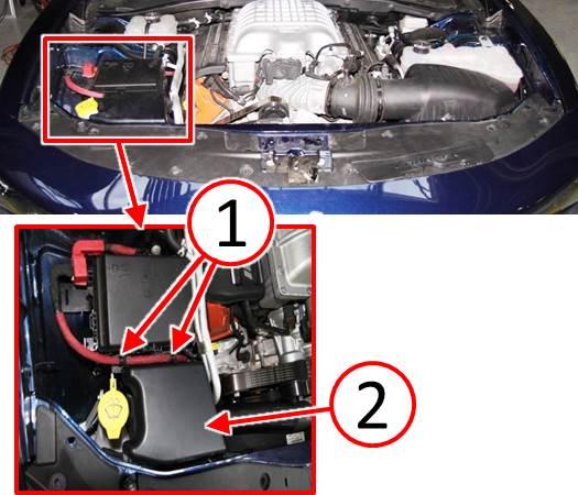
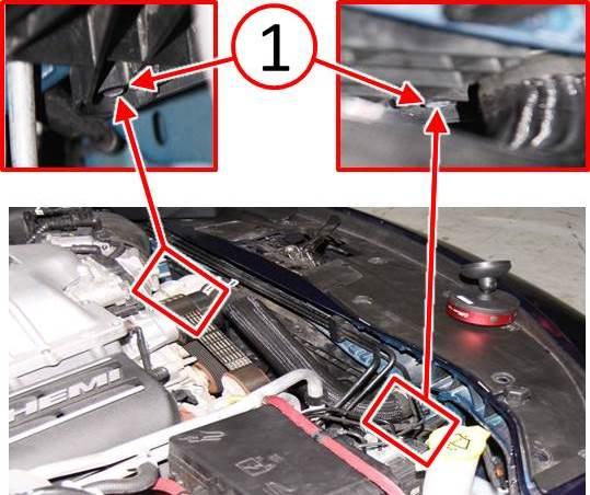
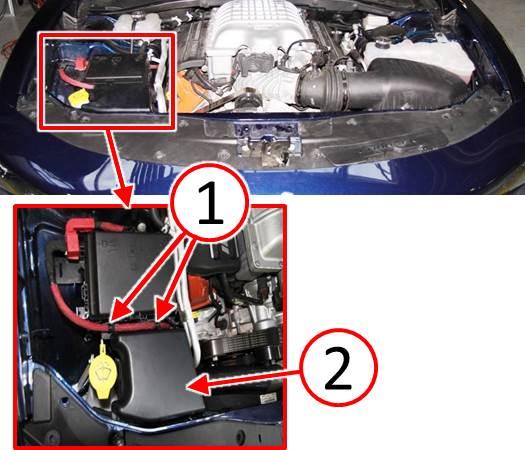
- Remove two push pin connectors (1) that wrap around battery cable and capture tabs on ABS Module cover (Fig. 1).
- Remove the ABS Module cover (2) (Fig. 1).
Fig. 1 Remove ABS Module Cover
1 – Battery Cable Push Pin Connectors
2 – ABS Module Cover
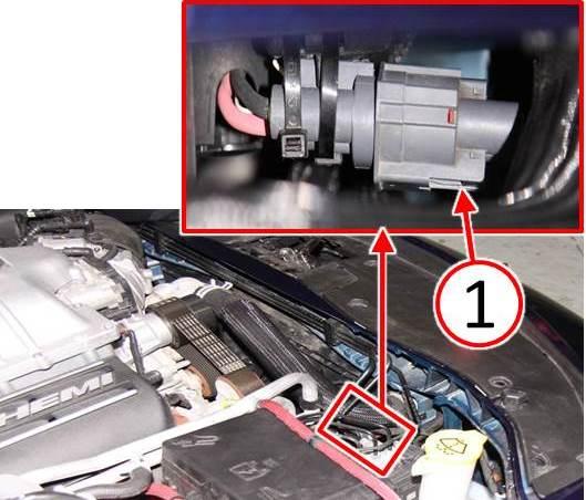
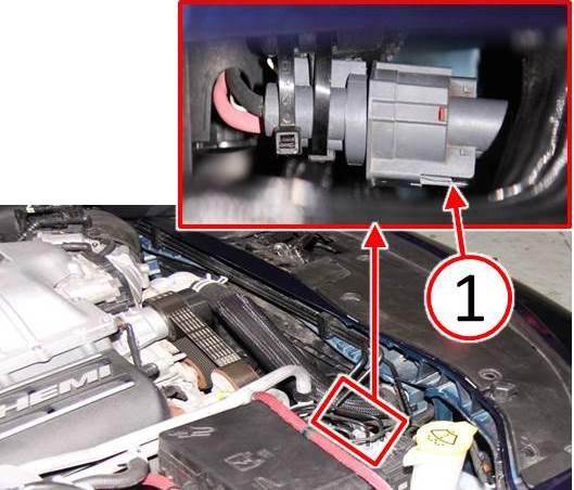
- Depress locking tab (1) then pull to disconnect the cooling fan electrical connector (Fig. 2).
Fig. 2 Disconnect Fan Electrical Connector
1 – Cooling Fan Electrical Connector Locking Tab
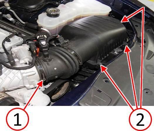
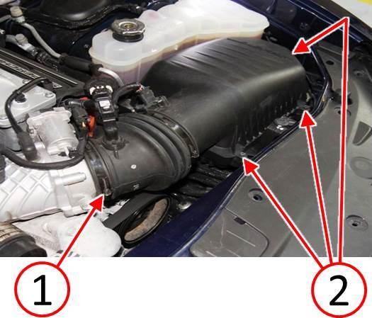
- Remove three screws (2) securing the air cleaner housing cover (Fig. 3).
- Loosen the air inlet duct clamp (1) then rotate the air inlet assembly up to provide access (Fig. 3). It is not necessary to disconnect electrical connectors or fully remove the air inlet from the vehicle.
Fig. 3 Air Inlet
1 – Air Inlet Duct Clamp
2 – Air Cleaner Housing Cover
- Remove the radiator fan mounting bolts (1) (Fig. 4).
Fig. 4 Remove Cooling Fan Mounting Bolts
1 – Radiator Fan Mounting Bolts
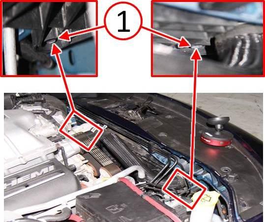
NOTE: Belly pan removal is not required for releasing the lower fan shroud clips. (Fig. 5) bottom views are provided for information only.
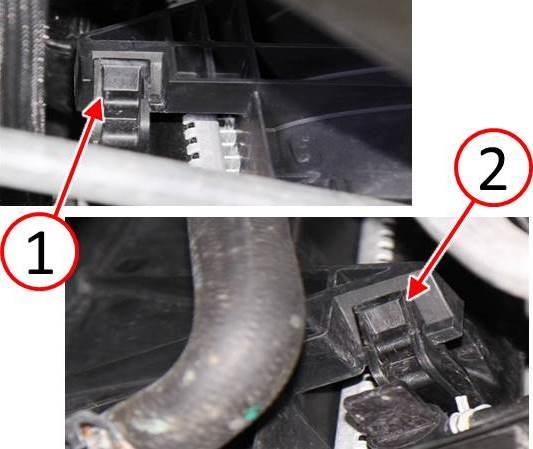
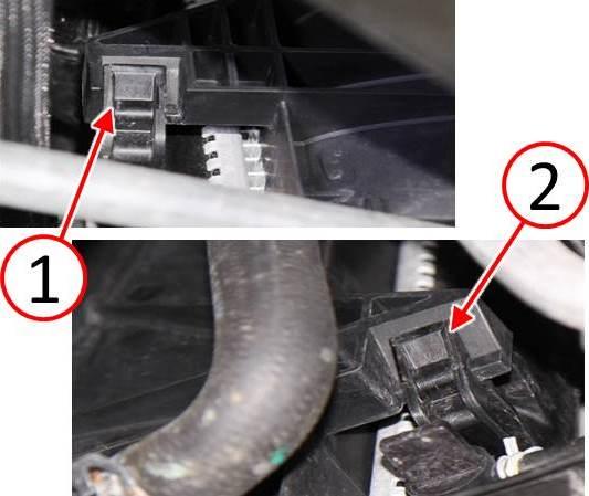
- Lift the fan assembly to release the lower fan shroud clips (1 and 2) (Fig. 5).
Fig. 5 Release Lower Fan Shroud Clips
1 – Left Fan Shroud Clip
2 – Right Fan Shroud Clip
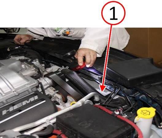
- Repositioned the fan shroud (1) leftward and rearward to gain access to the right side radiator tank crimp tabs (Fig. 6).
Fig. 6 Reposition Fan Assembly For Radiator Tank Crimp Access
1 – Fan Shroud
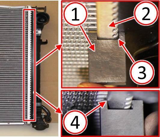
- Insert the radiator crimp inspection tool (1) over the crimp flange (2) checking for tool clearance or interference along as much of the radiator tank crimp flange as is accessible. The inspection tool should fit freely around the crimp flange without interference (3). If the inspection tool interferes with the crimp flange (4) not fitting freely over the flange, at any location along the entire length of the crimp flange, the radiator will require replacement.
Fig. 7 Inspect Crimp Height Using Gage
1 – Inspection Tool
2 – Radiator Crimp Flange
3 – Inspection Tool Clearance
4 – Inspection Tool Interference
- Was any interference between the inspection tool and the crimp flange found at any location along the entire length of the crimp flange?
- a. YES>>> Continue with Step #13.
- b. NO>>> Proceed to Step #49
- Raise and support the vehicle. Refer to the detailed service procedures available in DealerCONNECT> TechCONNECT under: Service Info> 04 – Vehicle Quick Reference> Hoisting> Standard Procedure.
- Remove both front tire and wheel assemblies. Refer to 22 – Tires and Wheels/Removal.
- Remove bolts and the belly pan.
- Remove the front fascia. Refer to the detailed service procedures available in DealerCONNECT> TechCONNECT under: Service Info> 13 – Frame and Bumpers> Bumpers> FASCIA, Front> Removal.
- Drain the cooling system. Refer to the detailed service procedures available in DealerCONNECT> TechCONNECT under: Service Info> 07 – Cooling – Standard Procedure.
NOTE: If RRT 15-029 has been previously performed on the vehicle, discard the torque limiting head clamp (do not reuse) a new torque limiting head clamp must be used.
- Remove the upper radiator hose from the radiator (do not discard the old spring style clamp).
- If equipped with supercharger, disconnect the push pin (1) securing the coolant tubes by the Power Distribution Center (PDC) (Fig. 8).
Fig. 8 Push Pin for Tubes
1 – Push Pin
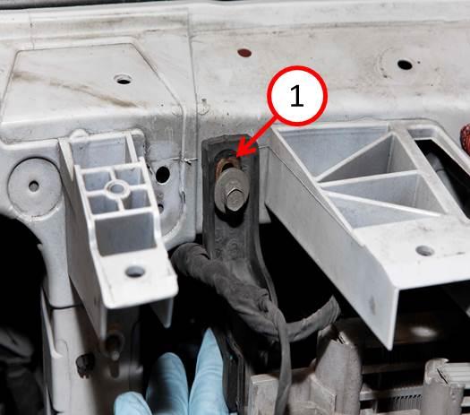
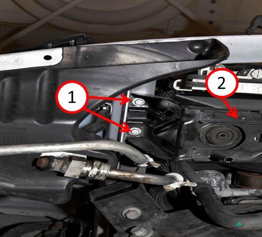
- Remove the bolts and the upper radiator support bracket (1) (Fig. 9).
Fig. 9 Upper Radiator Support Bracket
1 – Upper Radiator Support
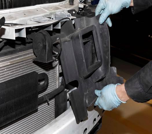
- Remove the radiator close out panels (Fig. 10).
Fig. 10 Upper Close Outs
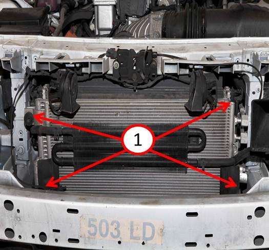
- Remove the 4 bolts (1) for the A/C condenser to the radiator and the Low Temperature Radiator (LTR) cooling system cooler if equipped with supercharger (Fig. 11). Secure the A/C condenser and LTR as an assembly to prevent stress on the lines/hoses.
Fig. 11 Bolts securing the AC Condensor
1 – Bolt Location
- Tie strap (2) the upper fan shroud (1) out of the way as shown (Fig. 12).
Fig. 12 Fan Shroud Tied Back
1 – Fan Shroud
2 – Tie Strap
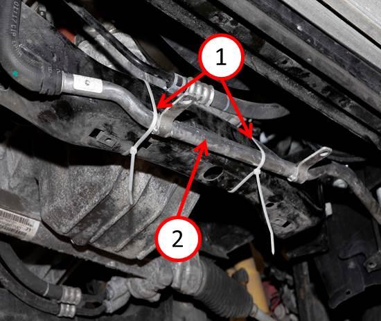
- Remove the push pins from the lower radiator support to the electric water pump for the LTR system tube (2) if equipped with supercharger. Tie strap (1) the tube back against the front cradle for clearance of the radiator (Fig. 13).
Fig. 13 LTR Tube Tied Back
1 – Tie Strap
2 – LTR System Tube
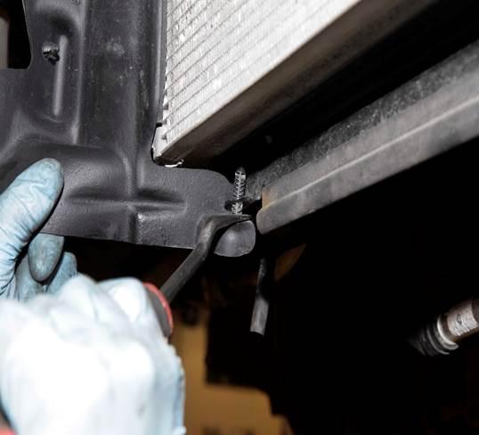
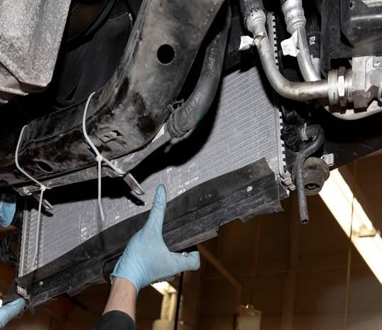
- Remove the lower radiator close out panels (Fig. 14).
Fig. 14 Lower Close Out
- Remove the lower radiator hose from radiator.
- Remove the 4 bolts (1) for the lower radiator support (2) (Fig. 15).
Fig. 15 Lower Radiator Support Bolts
1 – Lower Support Bolts
2 – Lower Support
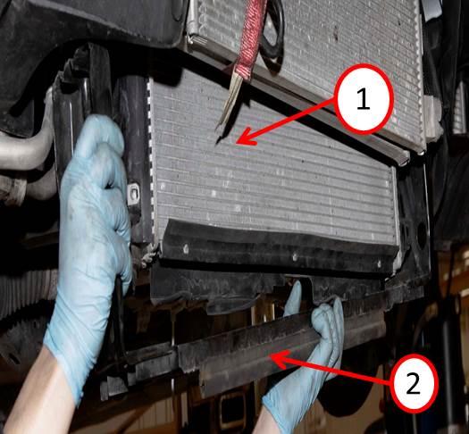
- Remove the lower support bracket (2) from the radiator (1) (Fig. 16).
Fig. 16 Radiator Lower Support
1 – Radiator
2 – Lower Support Bracket
CAUTION: Use extreme care when removing and installing the radiator not to damage the fins with the tight clearance area.
- Remove the radiator from the bottom of the vehicle (Fig. 17).
Fig. 17 Radiator From Bottom Of Vehicle
- Transfer all necessary components from the radiator to the new radiator.
- Install the radiator from the bottom of the vehicle (Fig. 17).
- Install the lower radiator support bracket (Fig. 16).
- Install the 4 bolts securing the lower radiator support (Fig. 15). Tighten the bolts to 16 N·m (141 in. lbs.).
- Install the lower radiator close out panels (Fig. 14).
- Remove the tie straps securing the LTR tube and install the push pins to the lower radiator support if equipped ( 13).
- Remove the tie strap securing the upper fan shroud (Fig. 12).
- Install the 4 bolts securing the LTR cooler if equipped with supercharger and A/C condenser to the radiator. Tighten the bolts to 9 N·m (80 in. lbs.) (Fig. 11).
- Install the radiator close out panels (Fig. 10).
- Install the bolts and the upper radiator support brackets (Fig. 9). Tighten the bolts to 12 N·m (106 in. lbs.).
- Install the lower radiator hose.
- Install the upper radiator hose.
- Install the push pin for the coolant tubes next to the PDC if equipped with supercharger (Fig. 8).
- Fill the cooling system with coolant. Refer to the detailed service procedures available in DealerCONNECT> TechCONNECT under: Service Info> 07 – Cooling – Standard Procedure.
- Verify there is no coolant leaking.
- Install the front fascia. Refer to the detailed service procedures available in DealerCONNECT> TechCONNECT under: Service Info> 13 – Frame and Bumpers> Bumpers> FASCIA, Front> Installation.
- Install the belly pan and the bolts (1).
- Install both front tire and wheel assemblies. Refer to the detailed service procedures available in DealerCONNECT> TechCONNECT under: Service Info> 22 – Tires and Wheels> Installation.
- Lower the vehicle.
- Insert the fan assembly into the lower fan shroud clips (1 and 2) (Fig. 18).
Fig. 18 Latch Lower Fan Shroud Clips
1 – Left Fan Shroud Clip
2 – Right Fan Shroud Clip
- Install the fan bolts securing it to the radiator. Tighten the bolts (4) to 9 N·m 80 in. lbs.) (Fig. 19).
Fig. 19 Install Cooling Fan Mounting Bolts
1 – Radiator Fan Mounting Bolts
- Reconnect the electrical connectors to the fan (Fig. 20).
Fig. 20 Connect Fan Electrical Connector
1 – Cooling Fan Electrical Connector Locking Tab
WARNING:Hot, pressurized coolant can cause injury by scalding.
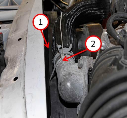
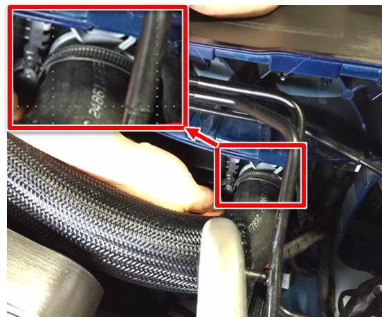
NOTE: When installing the new clamp, the original will remain in place. The new clamp should be positioned between the existing clamp and the radiator outlet flange. Take care not to overlap the clamps.
- Reposition the original upper radiator hose clamp forward toward the radiator if necessary to prevent clamp overlapping.
- Open the new clamp and place it over the radiator hose along side of the original spring clamp (do not discard the old spring style clamp). The hex head of the clamp should be facing up and be oriented on the core side of the radiator as shown in (Fig. 21).
Fig. 21 Radiator Hose Clamp Orientation
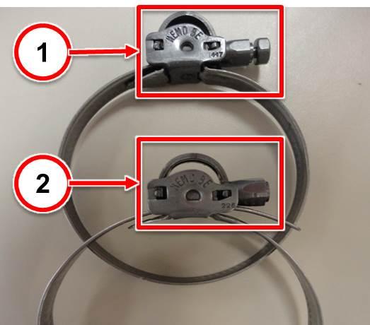
NOTE: The new clamp will have a torque limiting head. The head will break free once proper torque of 3 N·m (26 in. lbs.) is achieved. Care must be taken to ensure the socket used only engages the head of the bolt to prevent over tightening the clamp.
- Using a 7 mm shallow socket and swivel, tighten the new clamp until the torque limiting head breaks free as shown in (Fig. 22).
Fig. 22 Hose Clamp Torque Limiting Head
1 – Before tightening
2 – After tightening
- air cleaner housing cover (Fig. 23).
Fig. 23 Air Inlet
1 – Air Inlet Duct Clamp
2 – Air Cleaner Housing Cover
- Install the ABS Module cover (2) ( 24).
- Install the two push pin connectors (1) that wrap around battery cable and capture tabs on ABS Module cover (Fig. 24).
Fig. 24 Install ABS Module Cover
1 – Battery Cable Push Pin Connectors
2 – ABS Module Cover
- Connect the negative battery cable to the Intelligent Battery Sensor (IBS). Refer to the detailed service procedures available in Dealer CONNECT> TechCONNECT under: Service Info> 08 – Electrical> 8F – Engine Systems> Battery System.
- Start engine and allow coolant to reach operating temperature of 54°C (129°F) to 94°C (201°F) then inspect for any coolant leaks.
POLICY:
Reimbursable within the provisions of the warranty.
TIME ALLOWANCE:
| Labor Operation No: | Description | Skill Category | Amount |
|---|---|---|---|
| 07-30-10-92 | Inspect Radiator Crimp Flange and Install Torque-Limiting Clamp (1 – Semi-Skilled) | 7- Cooling | 0.6 Hrs. |
| 07-30-10-90 | 6.4L Engine – Inspect Radiator Crimp Flange, Replace Radiator, and Install Torque-Limiting Clamp (1 – Semi-Skilled) | 7- Cooling | 2.6 Hrs. |
| 07-30-10-91 | 6.2L Engine – Inspect Radiator Crimp Flange, Replace Radiator, and Install Torque Limiting Clamp (1 – Semi-Skilled) | 7- Cooling | 2.7 Hrs. |
FAILURE CODE:
| ZZ | Service Action |
 Loading...
NUMBER: 07-005-15
GROUP: Cooling
DATE: March 21, 2015
 Loading...
- Item Name: MOPAR Antifreeze/Coolant 50/50 Prediluted MS.90032
- Part Number: 68163849AB
- Brand: MOPAR
- Application: 2017-2020 ALFA ROMEO
 GIULIA, 2018-2020 ALFA ROMEO
 STELVIO, 2017-2019 CHRYSLER
 PACIFICA, 2016 (CHRYSLER
 TOWN & COUNTRY), (DODGE
 DART), 2016-2017 (CHRYSLER
 200), (DODGE
 VIPER), (JEEP
 PATRIOT), 2016-2019 (CHRYSLER
 300), (DODGE
 JOURNEY), (RAM
 1500, 2500, 4500, 5500)
 - 2015-2019 DODGE
 CHALLENGER, 2016-2020 (DODGE
 CHARGER, GRAND CARAVAN), (JEEP
 COMPASS), 2016-2021 (DODGE
 DURANGO), (RAM
 PROMASTER 1500, 2500, 3500), 2013, 2016-2018 FIAT
 500, 2016-2019, 2021 JEEP
 CHEROKEE/GRAND CHEROKEE, 2015-2021 JEEP
 WRANGLER, 2015-2020 RAM
 3500
3500
- Genuine MoparYear/ 150,000 Mile Coolant
- 1 Gallon Concentrate Bottle
- Contains a bittering agent
- Safe for all radiators and all gas/diesel engines
- PREDILUTED ANTIFREEZE AND COOLANT: Engineered to support any vehicle's engine cooling system to enhance performance and provide protection. This item contains a bittering agent called Denatonium Benzoate.
- PROPRIETARY BLEND: Contains 10X the scale-fighting inhibitors to ensure maximum cooling performance while protecting against scale, corrosion, and other damage
- SUPERIOR CHEMISTRY: Free from 2-EHA, silicate, nitrite, borate, and amines to keep your vehicle functioning in prime condition
- UNIVERSAL FORMULA: Compatible with any color or type of existing antifreeze and coolant in your car's system
- LONG-LASTING: Offers 2X the average warranty coverage, cooling your engine system for over 10 years or 300,000 miles of service
- Package Weight: 4.227 kg
- Product Type: Auto Part
- Package Quantity: 1
- No Batteries Required
- Embittered - Contains Bittering Agent
- UNSURPASSED FREEZE PROTECTION AND ANTI-BOIL PERFORMANCE outperforms industry standards
- HYBRID ORGANIC ACID TECHNOLOGY FIGHTS RUST, SCALE & CORROSION while protecting all cooling system metals (including aluminum)
- HIGH-QUALITY ADDITIVES PROTECT AGAINST LEAKS and won’t harm gaskets, hoses, plastics or original vehicle finish
- PRE-MIXED YELLOW FORMULA IS READY-TO-USE in a 50/50 ratio with deionized water to protect all modern engine components from winter freezing (-34F) and summer boiling (265F).
- 5 YEAR/150,000 MILE GUARANTEE protects against engine failure caused by freeze-ups or boil-overs
- 1 GALLON ENGINE ANTIFREEZE/COOLANT: Fully compatible with other extended life antifreeze/coolants. This item contains a bittering agent called Denatonium Benzoate.
- PROTECTS: Advanced formulation prevents rust & corrosion protecting all engine cooling system components
- DESIGNED FOR NORTH AMERICAN VEHICLES: Recommended for use with Ford, Chrysler
 , and GM vehicles that require an orange organic acid technology formula
 - GUARANTEED: When installed as part of a complete flush and fill, PEAK guarantees this coolant will provide service life protection of up to 150,000 miles or 5 years.
- CONCENTRATED FORMULA: Ideal for flushing, filling, or topping off your cooling system
- Unsurpassed freeze protection and anti-boil performance outperforms industry standards
- Organic acid technology resists rust, scale & corrosion while protecting all cooling system metals (including aluminum)
- High-quality additives protect against leaks and won’t harm gaskets, hoses, plastics or original vehicle finish
- Orange concentrate formula should be mixed with clean tap water or demineralized water at 50/50 ratio for temperatures -34 to 265F; 60/40 for -62 to 270F; and 70/30 for -84 to 267F
- 5 year/150,000 mile guarantee protects against engine failure caused by freeze-ups or boil-overs
- 5-Year/100000 Mile
- Genuine OEM Dodge/Mopar factory fit part
- Package Dimensions: 16.8 " L x 15.9 " W x 5.4 " H
- Fit type: Vehicle Specific
- 1 GALLON ENGINE ANTIFREEZE/COOLANT: Fully compatible with other extended life antifreeze/coolants. This item contains a bittering agent called Denatonium Benzoate.
- PROTECTS: Advanced formulation prevents rust & corrosion protecting all cooling system components. This product contains a bittering agent.
- DESIGNED FOR NORTH AMERICAN VEHICLES: Recommended for use with Alfa Romeo, Chrysler, Dodge, Fiat, Jeep and Rams that require a purple formula
- GUARANTEED: When installed as part of a complete flush and fill, PEAK guarantees this coolant will provide service life protection of up to 350,000 miles or 5 years.
- 50/50 PREDILUTED FOR QUICK TOP OFFS: Already prediluted to make topping off your cooling system a breeze
- Contains Alugard Plus for compatibility with all ethylene glycol-based coolants in automobiles and light duty trucks
- Fights corrosion, scaling and rust while protecting all cooling system metals (including aluminum)
- High-quality additives protect against leaks and won’t harm gaskets, hoses, plastics or original vehicle finish
- Pre-mixed yellow formula is ready-to-use in a 50/50 ratio with deionized water to protect all modern engine components from winter freezing (-34F) and summer boiling (265F).
- Contains 30 – 50 ppm of denatonium benzoate as a bittering agent
Last update on 2025-05-08 / Affiliate links / Images from Amazon Product Advertising API
This product presentation was made with AAWP plugin.
